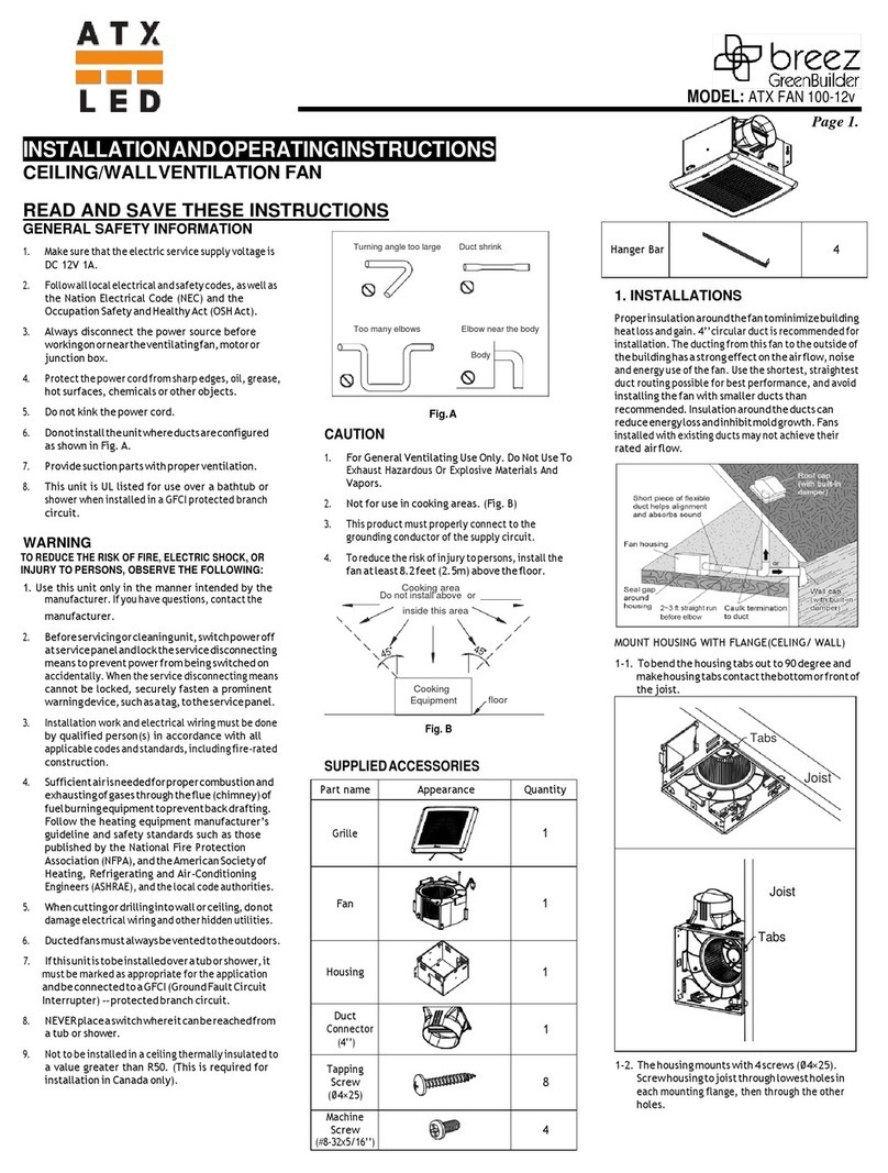
ATX AL-WS-DR2 User manual

ATX LED Consultants Inc
815-A Brazos #326
Austin TX, 78701
512 377 6052
http://atx-led.com
AL-Bath/Fan
Decorator style Switch/Driver
LED and Fan combo
Product Description - AL-Bath/Fan combo
This switch and fan combo enables low voltage control of humid areas – the fan will
exhaust the air, and the light illuminates
Various fan specifications are supported, for CFM and depth and duct diameter
Various Switch options are provided, with timing and speed controls available.
The wall switch operates just like any standard residential light switch – however it
takes 24-51v DC instead of 120VAC, and directly drives up to 28 watts of LED bulbs
and a 12 watt Fan. This Decorator style switch in a standard residential style outline
fits into any home, looks like any switch yet meets NEC article 411 for Low Voltage
lighting.
For Fan control - a simple 2 wire link with AWG24 or better to a simple UL listed
switch allows the fan to be controlled by the user. Any single pole switch found at
Home Depot can be used, or the AL-WS-M momentary switch can be used for
advanced timer controls.
Stand alone it operates as a simple switch for 1 strings of LED’s and 1 fan. Use
AWG 16 or 18 to bring 48v ( or 24 to 52 volts ) from a central power supply over to
the switch, then use AWG 20 to connect to your LED and Fan – no crimping tools
are required to wire this device.
A proven rocker switch and brightness slider leverages mass production of Decorator
switches, now for low voltage applications – a casual user requires no training, no
App to use this switch. Perfect, flicker free dimming from off to 0.1% to 100%. No
network setup is required.
To enable Home / Business automation – the AL-WS-DR2 includes a DALI opto
isolated serial bidirectional port for remote and voice control. Use the AL-DALI-Pi
Hub to connect to Alexa or Google home voice control. The DALI protocol is
supported, with automatic addressing. Use low cost wire in uncomplicated topology
to implement remote management. Power and DALI have in and out connectors to
avoid wire nuts.
Connect 48 volt strip lights for 30 watts installations, 24 volt strip lights up to 15
watts.
Exhaust Fan

Switch Specifications
Power source and Pass Thru Spring loaded connectors ( 2 pairs )
for AWG 16-20 wire
LED constant current output 660 mA with dimming to 30 mA (B) or 3 mA
Spring loaded connectors ( 2 pairs )
FAN output 12 volts, 1 amp with speed control to 7 volts
Input voltage range 24v to 52 volts ( power for LEDs)
Standby power consumption 50 milliwatts
Conversion efficiency Over 95%
Protection Reverse protection and static protection
Operating Temperature 0°C ~ 50°C
Size 108H (metal) 70H x 34 D x 42 W mm
Dimming 100% to 0.5% ( 5% B)
FCC and interference All outputs are RF filtered for minimal
interference, FCC compliance tested
Maximum output voltage Input minus 4 volts
Minimum output voltage 6 volts, self calibrating
Strip LED support ( CV Mode) Autodetect 24v CV strips
Protection Short Circuit, Overvoltage, hot swap – you can
unplug and connect LEDs with power applied.
User Error tolerant Detects and displays user errors
DALI interface
Individual, group and scene
support ( Optional)
Opto Coupled AWG 18-24 gauge wire spring fit
short and long addresses 16 to 24 volts 2 mA
N-Way input Simple contact for Fan control
see “Software N-Way Operations”
LED output A Top Left
LED / PIR / Fan output B Top Right
FAN Timer 0 to 90 minutes – using DALI commands
Exhaust Fan – ATX FAN 12v
Description
Low noise ceiling/wall mount ventilating fan with super low profile, rated for continuous running. It uses the SLM70 assembly
which is ENERGY STAR® qualified and is HVI, UL, and cUL certified, and can be used to comply with ASHRAE 62.2 (local
and whole building intermittent operation). The adaptation to 12v is pending UL.
DC Motor/Blower
•
Working voltage 12Vdc, operating voltage 8~12Vdc
•
Insulation strength 10M Ohm(Min.)
•
Dielectric strength 700VAc 60Hz
•
Start-up inrush current limited to 240 mA non-inductive load, steps up to 1 amp after 300 mS
•
Builtin soft start function
•
Motor equipped with thermal cutoff fuse
•
Locked rotor protection, powers OFF when impeller is locked abnormally
•
Removable with permanently lubricated plugin motor
•
DC brushless motor engineered to run continuously
•
Built in polarity and overvoltage protection
Housing
•
Galvanized steel body
•
Detachable 3” diameter duct adapter

Wiring the AL-WS-DR2 Fan and Light

Ordering Information
Control 50 cfm slim 70 cfm slim 80 cfm 100 cfm slim 100 cfm
Wall Switch 3 inch 3 inch 4 inch 3 inch 4 inch
AL-WS-DR2 AL-FF-50D AL-FF-70D AL-FF-80D AL-FF-100SD AL-FF-100D
AL-WS-DR2C AL-FF-50 AL-FF-70 AL-FF-80 AL-FF-100S AL-FF-100
AL-WS-Bath AL-FF-50B AL-FF-70B AL-FF-80B AL-FF-100SB AL-FF-100B
Powering the Wall Switch
Power the switch via either of the 2 power input connectors, 48 to 56v is recommended. You can pass power thru
from one set of power connectors to the other to avoid wire nuts in the box, up to 2 amps. After power up – the
first time the switch is operated you will see a flicker while it learns the capability of the attached LED. After that
phase – the result is stored in on-board EEprom and will be updated for temperature and aging changes or each
time the slider is moved to low dim. When used with a 51 volt supply, voltage drop of up to 3 volts ( 150 ft of
AWG18 wire) has no impact even with 60 watts of LED loads.
Series LED wiring
The LEDs are wired
in series
The simple strip and poke OJ-
606 connectors are easy to
install in ceilings.
If you only cut the Red wire –
you can save time and work
by wiring as shown at left.
From 1 to 5 LEDs can be
connected on each side.
Set the jumpers for 300,
360,660 or 720 mA
Note: for 6 watt LEDs:
a) 5 in series at 660 mA / 51v
b) 4 in series at 660 mA /48v
c) 2 in series at 360 mA
Trouble Shooting
If the LEDs do not turn on at full brightness, or flash – please check common causes;
1. Flashing the first time the light is turned on, or if the number of LEDs per side changes, is part of self calibration, please
wait 1 minute for this to complete.
2. If no light – then the number of series LEDs is exceeded. The forward voltage of the LEDs is too great. The delivered
voltage is between 7 and 42 volts ( with a 48 v supply) or 46 volts ( with a 51 volt supply). Check the forward voltage of
the LEDs and add them up. For example, a 6 watt 360 mA bulb has 18 volts forward, a 6 watt 660 mA bulb is 9v.
if your LEDs add up to more than 42 or 46 volts - they will not turn on at full brightness, and might not turn on at all.

AL-WS-DR2 and AL-WS-DR2C Operation
Momentary or On/Off Main Switch operation
The main switch of the device can be either On/Off type or Momentary. On/Off has the dimmer on the right, Momentary is
installed with the dimmer on the left. The difference is that each press of the Momentary style causes the light to turn On/Off.
Main switch functions – Momentary style
A momentary switch springs back to On when the lever is pressed down, an On/Off does not spring back (On/Off see below)
When installing a momentary switch type - the slider is on the left and the PCB is upside down.
Function Press How to trigger
On / Off
½ second
Push the switch down for under ½ second. The light will turn on and
off each time you press.
Reset to defaults:
Recalibrate the LED currents
Set switches to On/Off style
60
Press and hold the button for 60 seconds. The switch will enter self
calibration mode the next time the light is turned on. The switch
method will change back to On/Off type. See below.
Restore to Momentary Style
5 times
½ second
Should the light not stay on when the momentary switch is pressed,
the device is in Rocker mode – for example after factory default.
Press the button 5 times with less than 0.5 seconds each to change to
Momentary operation.
Main switch functions – On/Off style
A momentary switch springs back to On when the lever is pressed down, an On/Off switch does not spring back When
installing a On/Off switch type, the Slider is on the right.
Function Press How to trigger
Exit Momentary Style
Turn ON
Wait 60
seconds
Turn OFF
Should the not act like a simple On/Off switch, then it might be in
Momentary style. A Factory reset will fix this.
Factory reset – press switch top in, wait 60 seconds, turn switch off.
The device will return to On/Off style and will recalibrate.
Reset to defaults:
waiting to calibrate
switches are On/Off type
8
Set the dim to low dim. Turn the switch on for 2 seconds. Now off
and on 8 times, quickly, leaving it on after the last flip. The brightness
will change to 50%, then go off
The switch will enter self calibration mode and the lights will flash.

AL-WS-DR2 and AL-WS-DR2C
Local Fan Controls
Fan Wiring
A SLM70-LVDC or similar fan can be connected to the Right Led/Fan output. It will be automatically detected and
operation will be in Automatic, manual or timer mode as described below in the N-Way section. The AL-WS-DR2
in fan mode has a 12 volt output and the SLM70-LVDC has a 4400 uf input capacitor that allows it to be
automatically detected. 12 fans will lower capacitance may not be detected.
Fan operation supports two types of switches, and also operation without a fan switch.
For On/Off type switches (not momentary)
A) Manual. In this mode – leaving the fan switch off keeps the fan off. You can turn the fan on/off anytime by
turning the switch on or off. It will turn on immediately and stay on 10 minutes after the light is turned off.
Turn the fan switch off to return to manual mode.
B) Timer. If the fan switch is left on, then each time the light is turned on, after 90 seconds the fan will turn on
and stay on for 10 minutes and turn off automatically.
For momentary switches
A) Press to start: each press adds 5 minutes run time, enables automatic operation
B) Press long to stop: press for 4 seconds and release to stop the fan, disables automatic operation
C) Automatic operation: Each time the light is turned on, after 90 seconds the fan will turn on and stay on for
10 minutes and turn off automatically. Press for 4 seconds and release to stop the fan now and exit
automatic operation.
For operation with no fan switch
A) Wire the N-way pin to the N-way Gnd pin. The fan will operate in Timer mode, otherwise it will not operate.

AL-WS-DR2 DALI Control
DALI is not required for the operation of the AL-WS-DR2 (DALI). See the AL-WS-DR2 data sheet for
DALI detailed commands and features.
By default – the AL-WS-DR2 only responds to DALI broadcast commands – it will not transmit. There is no group
or short address assignment. Since the device accepts DALI broadcast commands – any DALI switch or master
that sends broadcast commands can connect to this device remotely for on/off/dimming – the LED outputs are
controlled by the switch or DALI broadcast packets. In Default mode – no DALI transmissions occur. DALI
received commands are treated like 3-way switch controls.
Full DALI Operation
For full DALI operation - connect your powered DALI bus to the DA+ and DA- pins (polarity is not significant ) of the
AL-WS-DR2. The device responds to the provisioning commands from a DALI master. In order for addressable
functions to work, a ‘short’ address [ 0 thru 63] needs to be assigned. This can be done by a DALI Master with
configuration features. Once a short address is assigned – the device can be understood to operate as two
devices in one.
1) LED driver with DALI control – the LED outputs will have a unique DALI short address after provisioning.
The LED driver outputs are connected to LED’s and each switch can now be individually controlled by DALI
commands from the bus. All DALI 60929-2006 commands are supported. The actual address and group
is defined and can be changed by the DALI master. See below.
2) Dimmer / Switch with DALI outputs – after provisioning – the mechanical front switch in this device is
placed into either short address or Group mode – see below – flipping the switch, or the 3-way remote
switches, or the slider dimming value will cause a DALI command to be sent internally to the LED outputs
as well as externally to the DALI bus.
3) A DALI Short Address Reset command will return the device to Broadcast receive mode and disable all
On/Off/Dim transmissions.
DALI Address Assignment - Auto - Grouping
The switch from the factory has no DALI Short address by default. When a DALI master assigns a short address
to the switch, one built-in feature rule has been implemented in all DALI ATX-LED devices.
•If the short address assigned is from 0-15, then the built-in switch will send a Group On/Off/Dim command
to the DALI bus each time the local status changes – On, Off, Dim – from the switch, slider or N-Way. This
method allows multiple AL-WS-DR2 to be configured as a gang – to all operate as one switch. After
assigning each DR2 a short address less than 16, add to each AL-WS-DR2 the group address of the
others to be ganged together. An AL-WS-010v can also be assigned to the same group.
•If the short address is from address 16-63, then the switch will output these state changes using its short
address, not a group address: An AL-WS-010v can be assigned the same short address to implement 3-
way control with dimming.
DALI commands also are used to determine the 3-Way state. Therefore, a DALI command with the matching
Group or Individual address will set the light on or off – and all local switches – physical or virtual – will reflect that
change – so that the next flip of any switch will turn the light off or on as intended.

DALI Fan control Programming
Intended for bathroom and utility fans, the Left output can be a dimmable light, the main switch and DALI control
the light. We introduce a timer function. A delay time between Light on and Fan on is defined, A Hold time of the
Fan on after the light goes off is defined. An idle speed can be defined for make up air, and the maximum speed
can be defined to control noise.
memory
Function Value Default Scale
0:15 N-Way Mode 2 – Use N-Way as the Fan On/Off switch
5:9 Driver mode 2 – Enable 12v fan operation
5:22 Fan Idle Sets the speed of the fan when it is ‘off’ 0 0-254
5:21 Delay before
ON
Seconds x 4 90 seconds 0 – 1020
5:20 Hold-ON Minutes 10 minutes 0 - 254
5:23 Fan Operate Sets the speed of the fan when it is ‘on’ 254 50-254
AL-WS-DR2C Operation and Installation
Setting Operational Modes
By default – the AL-WS-DR2C or DR2L operate stand
alone – no WiFi connection is required. For up to 4
standard LEDs with 660 mA each
The device is factory calibrated for operation. After
power up – you will see a 2 second ON time with the
lights at a very low dim level while it learns the capability
of the attached LEDs in your installation. After that
phase – the result is stored in on-board EEprom and will
be updated for temperature and aging changes over
time. You can force the device to factory defaults from
the switch front if needed ( see table below)
Operation setup – LED + FAN
Two DIP switches select the 4 operating modes – set 1 OFF and 2 ON for LED plus Fan. In this mode, the main
switch controls the LED, and the external switch ( if connected ) controls the FAN.
Slider Operation:
The Slider changes the brightness of the LEDs when the switch is ON.
N-Way Operation
See the Fan Control section for use with On/Off, Momentary or no external switch

AL-WS-Bath Operation
Light connection
Please see page 4
Fan Connection
A SLM70-LVDC or similar fan can be connected to the Fan output. The AL-WS-Bath in fan mode has a 12 volt
output at 1 amp.
Fan and Light operation
The On/Off switch and slider on the AL-WS-Bath control the dimming of the attached LEDs.
The Fan can be turned on with the light at the same time ( no external switch) or it can be operated by the remote
switch. A red dip switch controls the selection. Upgrade any time to full timer based control, or add on our Motion
sensor for automatic operation and timers.


This manual suits for next models
18
Table of contents
Other ATX Fan manuals
Popular Fan manuals by other brands

Tru-lite
Tru-lite Ultra Low-Profile Solar Attic Fan installation instructions

Adler Europe
Adler Europe AD 7326 user manual

RAMFAN
RAMFAN EX150Li owner's manual

Cumberland
Cumberland Mega-Flow External Damper Series owner's manual

Chillout
Chillout GF602 operating instructions

Westinghouse
Westinghouse Contempra Trio owner's manual