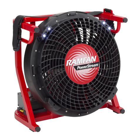
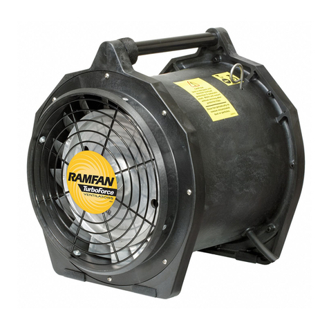
RAMFAN EX150Li User manual

San Diego |Luxembourg |Dubai |Ningbo | Singapore
FlowPath™Control
REVISIONS
ZONE
REV.
DESCRIPTION
DATE
APPROVED
D
C
B
A
A
B
C
D
1
2
3
4
5
6
7
8
8
7
6
5
4
3
2
1
MODEL FILE NAME:
DRAWING FILE NAME:
Configuration
Description
APPROVED
DRAWING INTERPRETATION
PER ASME Y14.5-2009
ALL DIMENSIONS ARE IN INCHES
UNLESS OTHERWISE SPECIFIED
.X ±.1
Euramco Safety Inc.
DO NOT SCALE DRAWING
.XXX ±.005
±1/64 .XX ±.02 ± 30'
FRACTIONS DECIMALS ANGLES
DRAWN
APPROVALS
DATE
REV
OF
SHEET
DWG. NO.
Material:
DO NOT MANUALLY UPDATE
CAD GENERATED DRAWING,
THE WRITTEN PERMISSION OF Euramco Safety Inc. IS PROHIBITED.
Euramco Safety Inc. ANY REPRODUCTION IN PART OR WHOLE WITHOUT
THE INFORMATION CONTAINED IN THIS DRAWING IS THE SOLE PROPERTY OF
EL6500-2-WHL
EL6500-2-WHL
Default
11
FIRST ANGLE PROJECTION
UNLESS OTHERWISE SPECIFIED DIMENSIONS ARE:
INCHES [MM]
TOLERANCES APPLY TO PRIMARY INCH DIMENSION
AND ARE AS INDICATED:
RADII: .015 MAX
UNLESS SPECIFIED
ON DRAWING
PART NO.
Finish:
C:\Users\pcanas\Desktop\
Owner's Manual
EX150Li HIGH-PERFORMANCE BATTERY FAN

CONTENTS
PRIOR TO FIRST USE
1. OperateonACvoltage,85-264V,50/60Hz1Φ,forcharginganddischarging.
2. TheunitissuitableforuseonGroundFaultprotectedcircuits.
3. ShouldtheprovidedACconnectorbeunsuitable,replacewithdesiredconnector
containingagroundingcircuit.Checkcontinuityfromgroundterminaltomotorshell.
4. PlacebatteriesintoholdersandconnecttoIP66connectors,Fullychargepriorto
rstuse.
5. Thisfanisforemergencyserviceuse.Chargefullybetweenruns.Createacharging
protocol.
6. Tocharge,turnthespeedcontrolfullytotheleft(OFF)andthenconnecttoACoutlet.
Indicatorlightswillilluminate,andthengoo.Whenchargingcommences,indicator
lightswillshowstateofcharge.Chargingshouldcompletein3-4hours,withthe
indicatorlightsturninggreen.
7. ForDCoperationwithACdisconnected,holdthewakebuttonuntil
indicatorlightscomeonshowingbatterystate.Advancespeedcontrol.
8. ForACoperation,advancespeedcontrol.
READ MANUAL BEFORE STARTING FOR THE FIRST TIME!
RAMFAN products are warranted against manufacture defect. Failure to
properly maintain product will invalidate warranty coverage. Please visit
www.euramco.com for warranty details.
ThankyouforpurchasingtheRAMFAN®EX150Lihigh-performanceventilator
manufacturedintheUSAbyEuramcoGroup,Inc.
Formorethan50yearsEuramcoGrouphasbeenonthecuttingedgeofindustrial,re,
andmarineventilationproducts.Eachofourblower/exhausters,PPV&LSVfansand
accessoriesrepresentthenesttechnologiesavailable.Everyproductisconstructedto
demandingandexactspecicationsforquality,performance,andreliability.
Whenhumanlifedependsonhavingafanthatcandeliverclean,safeair,youhaveonlyone
choiceyoucantrust:RAMFAN.
Exploreourwebsiteandonlinecatalogatwww.ramfan.comanddiscoverhowRAMFAN
canmakeadierenceintheeld!
Allproductinformationinthepublicationisbasedonthemostcurrentinformation
availableatthetimeofprinting.EuramcoGroup,Inc.reservestherighttomakechangesat
anytimewithoutnotice.
Unit Description ..............................................................................................................................4
PartsList............................................................................................................................4
Warning Labels & Safety Pecautions ........................................................................................5
Specications....................................................................................................................5
Main Interface ................................................................................................................................6
Plug Types ........................................................................................................................................7
Adjusting Angle ...............................................................................................................................8
Operational Modes ........................................................................................................................9
ACOperation....................................................................................................................9
DCOperation....................................................................................................................9
Connection of Battery Pack...................................................................................................9-10
Battery Operation Procedures............................................................................................11-12
RunTime.........................................................................................................................12
ChargingProcedure.......................................................................................................13
Fuel Gauge.....................................................................................................................................14
Battery Status Indicator Lights.................................................................................................15
BatteryPackProtection.................................................................................................15
Storage/TransportModes.............................................................................................16
HowtoActivate"Storage/TransportMode"..............................................................16
ACPowerCord...............................................................................................................17
OperatingLimitations....................................................................................................17
Lithium-Ion Battery Maintenance Guidelines........................................................................18
Overview.........................................................................................................................18
Storage............................................................................................................................18
Recommendation...........................................................................................................18
Maintenance and Disposal.........................................................................................................19
MaintenanceSchedule..................................................................................................20
Accessories....................................................................................................................................21
Certication...................................................................................................................................22

4 5
Warning Labels & Safety Precautions
Thisisthesafety-alertsymbol.
Whenyouseethissymbolonyourventilatororinthismanual,bealerttothepotentialfor
personalinjuryordamagetoyourequipment.Besureyouunderstandallsafetymessages
andalwaysfollowrecommendedprecautionsandsafeoperatingpractices.Important
safetyinformationispresentedinthissectionandthroughoutthemanual:
• Electricalshockhazard.Donotopentheunit.
• DONOTSTARTwithsignsofvisibledamage.
• Ventilatorisnotintendedforoperationinexplosiveatmospheres.
• Wearearprotectionwhencloseby.
• Keepbodypartsandlooseobjectsawayfromintakeofventilator.
• Donotmoveventilatorwhileinoperation.
• Operateandrepairbytrainedpersonnelonly.
• AlwaysusegroundedplugandproperlygroundACpowerreceptacle.
• Heatsinkbecomeshotduringchargingtosomeextent.DONOTtouch.Donotplace
itemsoverheatsinkarea.
• Usewithapproved,goodconditionextensioncordwiththegroundconnector:
Wire Gauge Requirements per ft (m)
0-150 ft (0-50m) AWG14(2.5mm2)
>150 ft (> 50m) AWG12(4mm2)
HOT SURFACE
!
DO NOT TOUCH!
DO NOT PLACE ITEMS OVER
HEAT SINK AREA!
KEEP
FINS
CLEAR
HIGH VOLTAGE
DO NOT OPEN
No User Serviceable Parts
CAUTION!
Unit Description
• TheEX150Liisamulti-purposeventilatorpoweredbybattery(s)or90-250Vsingle
phase,50-60HzACpowersource.Itsmultipurposeframecanbeconguredfor
PPV,smokeejectororductedventilatoruseinbothnormal,horizontalandhanging
positions,all-terrainwheeledmobilityorurbanwheeledmobility.
• Themotorisavariable-speedBLDCmotorcontrolledbyamicroprocessorintegrated
withapowersupply,dualbatterychargersandanLEDlightdriver.
• TheEX150Liwillrunwithoneortwo52V8AhLithiumIonBatteryPacks.Thebatteries
maybeswappedduringoperation.
• ACvoltagecanbeappliedwhilerunningonbatteriesandtheventilatorwillauto-switch
toACpower.Conversely,theACpowercanberemoved,andtheunitwillauto-switch
tobatterypower,ifenoughchargeremainstopowertheventilator.
• Theintegratedbatterychargerswillchargeoneortwofullydischargedbatterypacksin
6hoursorless.
• LEDscenelightsareintegratedintotheventilatorshroudandhavea3-intensity
inniteswitchknob:high,lowando.Turntochange.TheLEDknobselectsthescene
lightsoutputlevelinarow.ClockwiseProgression:OFullHalfO.
• AControlPanelonthetopoftheunitcontrolsallfunctions.
Parts List
Qty Description
1VentilatorEX150LiwithAll-Terrainwheelkitassembled
2Lithium-ionBatteryPackM1-52V8Ah
1PowerCord
1ExtendableHandles
REVISIONS
ZONE
REV.
DESCRIPTION
DATE
APPROVED
D
C
B
A
A
B
C
D
1
2
3
4
5
6
7
8
8
7
6
5
4
3
2
1
MODEL FILE NAME:
DRAWING FILE NAME:
Configuration
Description
APPROVED
DRAWING INTERPRETATION
PER ASME Y14.5-2009
ALL DIMENSIONS ARE IN INCHES
UNLESS OTHERWISE SPECIFIED
.X ±.1
Euramco Safety Inc.
DO NOT SCALE DRAWING
.XXX ±.005
±1/64 .XX ±.02 ± 30'
FRACTIONS DECIMALS ANGLES
DRAWN
APPROVALS
DATE
REV
OF
SHEET
DWG. NO.
Material:
DO NOT MANUALLY UPDATE
CAD GENERATED DRAWING,
THE WRITTEN PERMISSION OF Euramco Safety Inc. IS PROHIBITED.
Euramco Safety Inc. ANY REPRODUCTION IN PART OR WHOLE WITHOUT
THE INFORMATION CONTAINED IN THIS DRAWING IS THE SOLE PROPERTY OF
EL6500-2-WHL
EL6500-2-WHL (2)
EXTENDED HANDLE
11
FIRST ANGLE PROJECTION
UNLESS OTHERWISE SPECIFIED DIMENSIONS ARE:
INCHES [MM]
TOLERANCES APPLY TO PRIMARY INCH DIMENSION
AND ARE AS INDICATED:
RADII: .015 MAX
UNLESS SPECIFIED
ON DRAWING
PART NO.
Finish:
C:\Users\pcanas\Desktop\
EXTENDABLE
HANDLES
ALL-TERRAIN
WHEELS
Wtigmgexmsrw
Model EX150Li 18"/46 cm
Order# EL6525
Motor 1.9Hp/1.4kw,BLDC
Runtime@Max.Speed
DC:45minutes(fourbatterypacks)
DC:30minutes(twobatterypacks)
AC:Unlimited
PowerAC UniversalInput:85-264V1Φ,50/60
HZ
BatterySystem 52VLithium-ion,832Wh,16Ah
IPRating
(Motor/BatterySystem/
Controller)
IP66/IP66/IP66
Dimensions(hxwxd) 23"x21"x21"in/58x53x53mm
Weight
withtwobatteries:77Ibs/35kg
withonebattery:70lbs/32kg
withoutbatteries:63lbs/29kg
OperatingTempRange -4°Fto105°F -20°C to 40°C
ChargeTempRange -32°Fto105°F -0°C to 40°C
Tilt 0°to+34°
Approvals AMCA
AMCAVeriedAirow
ACPowerSupply 12,377cfm(21,029m3/hr)
DCPowerSupply 11,896cfm(20,211m3/hr)
23"
21" 21"

6 7
Main Interface
Control Panel:
AC PWR
PRESS
ON/OFF
PRESS FOR
MAX
L
R
DC PWR
MAX
FAULT
L
BAT. FAULT
NO PWR
STORAGE
MODE
Intellisense
TM
E3
HI OFF
LOW
AIRFLOW
LIGHTS
5
6
4
3
Number Symbol Indicate Function
1WakeButton/EmergencyStopButton
PressandholdWAKEbuttontostart.
2MaximumSpeed(DC)Button
PressMAXbuttonfor2seconds.
3LEDSceneLightsknob
On,o,onhighoronlow.
4SpeedControlknob
Controlledoperationfrom0tofullspeed
5
BatteryStatusLEDLights
6
VentilatorStatusLEDLights
Seetablebelowfordetails.
L
R
BAT. FAULT
Color Status Description
O NOPWR Poweriso
Green (Solid) ACPWR VentilatorisconnectedonACPowerSupply
White (Solid) DCPWR VentilatorisrunningonDCPowerSupply
White (Flashing) MAX VentilatorisrunningonMaximumspeed-DC
PowerSupply
Red (Flashing) FAULT Faultontheventilator
Yellow (Flashing) STORAGEMODE Storage/TransportMode
Plug Types
TheEX150Liissuitableforworldwideapplications.Avoltageconverterisnotneeded.The
unitincludesasimpleremovablecordthatallowstheunittooperateupto250VAC:
Mainlyusedin Type Order#
NorthandCentralAmerica,Japan BEL-CUS-4762
France,Belgium,Germany,Austria,the
Netherlands(andmostEuropeancountries)
E/F EL-CEU-4762
UnitedKingdom,Ireland,Malta,Malaysiaand
Singapore,HongKong,Nigeria
G EL-83070-4762
Australia,NewZealand,PapuaNewGuineaand
Argentina
I EL-84040-4762
China,P.R.C. I EL-84640-4762
Ifitbecomesnecessarytouseapowercordwithanotherplugstandard,orderthepower
cordthatmatchestheelectricalrequirementsofthecountryorarea.Thephysicaladapter
fortheoutletisinterchangeableforuseindierentcountriesandallowsyoutoswapthe
cableyourselfintothesocket.
ThispageshowsaselectionofelectricplugswecancurrentlyoerfortheEX150Li.
Ifyouneedaspecialsolution,justinformyourlocalEuramcorepresentativeaboutthe
specic.
2
1
AC PWR
DC PWR
MAX
FAULT
NO PWR
STORAGE
MODE
AC PWR
DC PWR
MAX
FAULT
NO PWR
STORAGE
MODE
AC PWR
DC PWR
MAX
FAULT
NO PWR
STORAGE
MODE
AC PWR
DC PWR
MAX
FAULT
NO PWR
STORAGE
MODE
AC PWR
DC PWR
MAX
FAULT
NO PWR
STORAGE
MODE
AC PWR
DC PWR
MAX
FAULT
NO PWR
STORAGE
MODE
LIGHTS
SPEED
LIGHTS
SPEED
AC PWR
DC PWR
MAX
FAULT
NO PWR
STORAGE
MODE

8 9
Adjusting Angle
Performthisproceduretoadjustthepositionoftheventilator.Useyourhand
tounscrewthetiltadjustmentknob,andthenlockitinplacefromabove,andheldinthe
inclinedpositionbytighteningtheknob.Fornegativetilt,usethenegativetiltbracket.This
providestiltup/downadjustment,from0to+34degrees.
Forconnedspacerescueoperations,youcanplacetheventilatordirectlyontopofa
manhole.Tiltrangefrom-90to+90degrees.Notethatthosepositionscandirectairow
downwardorupward
Negative tilt bracket
(Accessory)
0o
-90o
+90o
34o
Loosen
Tighten
Tilt adjustment knob
Connection of Battery Pack
DC Operation
• Plugtheventilatorconnectorcable(blue)intothebatteryconnector:
• Settheinstallationindexonthebatterywiththecable,liningupwiththecable
connector.
• Presstheconnectorlockandrotatethebluepiececlockwise(aquarterturntothe
right)inthemostcarefulwaypossible.
• Aligntheedgeofthebatterypackwithholderundertheredlinewhereitsays,“Align
batteryEX150Li”andrmlyslidethebatteryinthedirectionofthearrowasshownin
theillustrationuntilaloudclickisheard.
Operational Modes
AC Operation
• InputVoltage.90-250VAC,50/60Hz
• Theventilatoriscapableofoperatingseamlesslyincountriesthatsupplyelectricityat
either120VAC/60Hzor240VAC/50Hzwithoutmanualadjustmentsbytheuser.
• Operationoutoftheselimitscandamageelectricalcomponentsandwillvoidthe
warranty.
1.ConnectthefantoanACpowersource.
2.StatusLEDLightwillautomaticallyturngreen,displayingthestatus“Ventilatoris
connectedonACPowerSupply”.
3.StarttheventilatorbyusingtheSpeedControlknobtothedesiredspeed.
Note:Youcankeepthebatteriesontheirlocationwithoutchargingthebattery.
BatteryIndicatorLightswillturnobecausethereisnobatterycharging
whenventilatorisrunningonAC.
4. Whenthefanispoweredo,StatusLEDLightwillautomaticallyturnoafter1hourand
thebatteryIndicatorLightswillredisplaybatterychargelevelofeachbatterypackdetected.
Theventilatorwillbeginchargingthebatterypacksafter60minutesofidletime.

10 11
EX50Li
DATE 12/09/20
ITEM#
LABEL# LB9113
REVISION -
DIMS* 1.5748 x 2.25 in
MATERIAL MainStock: TEC4911 4Mil Vinyl Flex White TC Vinyl UL 50#SCK w/Permanent Adh
COLOR Black, Red
A Switched directions of arrows 06/30/20
- Label Created 08/27/19
Revision Description Date
HISTORY - LB9113
B Moved arrows down to touch red
line and moved alignment text to its
side. 12/09/20
ALIGN
40V
LB9113 Rev B
ALIGN
52V
ALIGN
40V
LB9113 Rev B
ALIGN
52V
• Gentlypulluptheyellowhandletoremovethebatteryfromtheholder.
Battery Charger Warn Label
DATE 07/07/20
ITEM#
LABEL# LB9114
REVISION -
DIMS* 1.25 x .875 in
MATERIAL MainStock: TEC4911 4Mil Vinyl Flex White TC Vinyl UL 50#SCK w/Permanent Adh
COLOR Black
- Label Created 07/07/20
Revision Description Date
HISTORY - LB9114
LB9114
40V & 52V
battery packs
are NOT
interchangeable
Battery Operation Procedures
Pleasefullchargebatterybeforerstuse
UsingOneBattery
• TheEX150Liallowstheoptionofusingoneortwobatterypacks.
• Whenusingonebattery,simplyplugthebatteryintoeitheroneofthetwobattery
connectors(leftorright).
• Besuretosecuretheunusedbatteryconnectorbyplacingelectricaltapeoverthe
contacts.
• Whenrunningfanonsinglebattery,operatingpowerislimitedtoreducemaximum
dischargecurrent--extendingusefullifeofbattery.
UsingTwoBatteries
• The EX150Li oers a true redundant dual battery system.
• Whenusingtwobatteriesofidenticalchargelevel,batteriesareconnectedinparallelto
increasesignicantlythetotalruntimeandairowperformance.
• Whenusingtwobatterypacks,eachpackfunctionsindependentlyandisisolated
fromtheothersothatifonepackshouldfail(opencircuit,short-circuit,orbecome
discharged)theotherbatterywillprovidepowertooperatethesystem.
• Whenusingdualbatteries,it’simportantthatbothbatteriesbeofthesamecharge
levelandideallyofthesameageandcondition.
• It’snormalforonebatterytodischargeslightlymorethantheother.Thisisthenature
ofatrulyredundantisolatedbatterysystem.
• Thebatterythathasthehighervoltagewilldischargeatafasterrate(untilitsvoltage
equalstheotherbattery).
• WerecommendthatusebothbatteriesontheSameStateofCharge(oratleastas
closeaspossible).Ifthisisnotpossible,thecontrollerwilleventuallybringbatteriesto
abalancedchargelevel.
• Tokeepbatterypackshealthyforlong-termuse,asimpleimplementationofcell-
balancing,internaltothebatterypack,includesaFETplacedinparallelwitheachcell
andcontrolledbyacomparatorforsimplevoltagebasedalgorithmsthatturn-onthe
bypassFETsduringtheonsetofvoltagedierences,controlledbyamicrocontroller
formorecomplexandeectivealgorithmsthatcanworkcontinuouslyregardlessof
variationsofvoltagedierences.

12 13
• WhenACisdisconnectedandSpeedControliso(speed=0),thecontrollerand
battery(s)willenterasleepmodetoconservethebatterypowerafter60minutesofno
activity.
• Towaketheventilator,pushandholdWAKE|STOPButtononControlPanel.
BatteryStatusLEDLightwillshowwhitesolidforthestatus.Theunitwillreturnto
sleepmodeifnotusedwithin10minutes.
• Theventilatorstartsatthelowerspeed=0.Speedwillvaryby11levels-from11
(highest)to0(o).Turnclockwisetoincreasespeed.Atlevel11(thehighest),ifkeep
turningthecontrolknobclockwise,thespeedwillnotchange,itwillstayathighest
speedallthetime.Toslowdown,turncounterclockwise.
• Ifyouwanttoincreasethespeed,pushandholdtheMAXButtonVentilator
StatusLEDLightwillashwhiteforthestatus.Rememberthatthiswillonlyworkwhen
2batteriesareconnectedtotheventilatorandwhenitisoperatingexclusivelyonDC
currentsource(battery).
• ToSTOPtheventilator,pushandholdWAKE|STOPButtononControlPanel.
BatteryStatusLEDLightwillbeunlit.
• Battery(s)maybeswappedforchargedbatteriesatanytime.
• Reducerunspeedtominimumrequiredtoincreaseruntime.
Battery Operation Procedures
Run Time
Runtimereferstohowlongtheventilatoronbatterypowerwilllastunderagivenload.
Wewillassumebothbatterieshavefullchargebeforehandandalso100%eciency(Read
"FactorsthataectBatteryLife"section):
2 Batteries Speed Level Knob
Atmaximumspeed 45minutes 11
AtmaximumspeedandMax
buttonactivated
30minutes Maxbuttonactivated
Charging Procedure
Battery
Fuel
Gauge
Makesurethebatterypackisconnectcorrectlyintotheventilator,asdescribedabovein
“Connection of Battery Pack”.
• Thenextstepistoleavetheventilatoro.Duringcharging,thebatteryindicatorlights
willash.Thebatterychargelevelcanberecognizedbythenumberoflightsthatare
constantlylit.
• IfbothbatteriesandACareconnected,thebatterieswillbeginchargingafter60
minutesofidletime.Ifonlyonesinglebatteryisconnect,thebatterywillbegin
chargingafter120minutesofidletime.
• Indicatorlightswillshowchargestateduringcharging.Chargingshouldcompletein
about5hours,withtheBatteryStatusIndicatorlightsturninggreenandalltheve
FuelGaugelights(ifbatteryisequippedwithgauge)onthebatteryturningred.Should
theSpeedControlbeturnedcounterclockwiseonduringthecharge,chargingwillstop,
andtheventilatorwillstart.Chargingwillbeginagainafter15minofidletime.
• Afterchargingiscomplete,thechargerswillmaintainthebattery(s)bykeepingthe
ventilatorconnectedtoAC.
• Whilecharging,thebatterystatusLEDlightswillstrobe,aswellasthebatterycharge
(ifequipped)indicatorstatuslightslocatedonthebatteryitself.Thebatterieswillbe
disconnectedattheendoftheirchargeautomatically.Attheendofcharging,the
currentpowerisdisplayedfor5minutesandthenlightswillbeturnedo.
• IfalltheFuelGaugelightsareashing,thisindicatesanerrorcondition.

14 15
AC PWR
PRESS
ON/OFF
PRESS FOR
MAX
L
R
DC PWR
MAX
FAULT
L
BAT. FAULT
NO PWR
STORAGE
MODE
Intellisense
TM
E3
HI OFF
LOW
AIRFLOW
LIGHTS
The Fuel Gauge
For batteries equipped with a battery fuel gauge:
TheBatteryFuelGaugeprovidesbatterystatusinformationusingveredLEDs.
PresstheFuelGaugebuttontodisplaythelights.Thefuelgaugelightswillremainlitfor
approximatelyveseconds.
ThenumbersrepresenteachLEDandthegridishowthey'relaidout:
FuelGaugeLights Diagnosis Solution
LEDs1-5:RedSolid RemainingRunTime ContinueWorking
LED1:RedFlashing
LEDs2-5:O
Lessthan13%runtimeleft ChargePack
LEDs1-5:RedFlashing BatteryTemperaturetoo
high
AllowBatterytoCool
35-55%56-76% 77-99% 100%
14-34%
Battery Status Indicator Lights
Onthecontrolpanelthereare2setsoflights:onthetopsideofthebatterylightsindicate
thechargelevelinthebatteryattachedtotheleftsideoftheventilator,onthebottomside
ofthebatterylightsindicatethechargelevelinthebatteryattachedtotherightsideofthe
ventilator.
Ifthebatteryischarging,thegreenindicatorlightswillhorizontallyscrollfromleft-to-right,
turningsolidgreenwhenthebatteryisfullycharged.
Iftheventilatorisrunningonbatterypower,theestimatedremainingbatterytimeis
shown.
Ifallthelightsashred,thisindicatesthatthebatteryhasfailedandthebatterymustbe
replaced.
Battery Pack Protection
• Toprotectitselffromdamageandextenditslife,thebatterypack'sintelligentcircuit
monitorscurrentdrawandtemperature.Inextremesituations,thebatterypackwill
turnOFFtheventilatorifthecurrentdrawbecomestoohigh.Allthefuelgaugelights
willash.
• Underextremecircumstances,theinternaltemperatureofthebatterycouldbecome
toohigh.Ifthishappens,thefuelgaugelightswillashinanalternatingpatternand
thetoolwillnotrun.
• Whileabatteryundergoesachargecycle,itstemperaturerises.Topreventgrid
corrosionandeventualbatteryfailure,allowthebatterytocooldowninbetween
charginganddischarging.
12345

16 17
AC PWR
PRESS
ON/OFF
PRESS FOR
MAX
L
R
DC PWR
MAX
FAULT
L
BAT. FAULT
NO PWR
STORAGE
MODE
Intellisense
TM
E3
HI OFF
LOW
AIRFLOW
LIGHTS
Storage/Transport Modes
Lithium-ioncellmanufacturersrecommendthatbatterycellsbestoredat30%state
ofcharge(SoC)forbestlong-termhealthandstability.Further,IATA(InternationalAir
TransportAssociation)DangerousGoodsRegulations(DGR)statethatalllithium-ion
batteriesmustnotexceed30%SoCattimeofshipment.
RAMFANbattery-poweredfansbuiltwithIntellisenseTME3controllersareequipped
withintegrated“Storage/TransportMode”tomakeiteasytocomplywithstorage
recommendationsandtransportregulationsbyautomaticallydischarginginstalledbattery
pack(s)to30%SoC.
How to activate "Storage/Transport Mode"
AC Power Cord
CORD
STORAGE
Pulltheplugoutitself,neverbythecordorbywigglingitoutoftheoutlet.
RAMFANlithium-ionbatterypacksaredesignedtooperateinawiderangeof
temperatures.Duetothechemistryoflithiumionbatterycells,dierentoperationallimits
applytodischargeandchargefunctionality.
• Temperaturerange(discharge):-20oC to +45oC(-4oFto+113oF)
• Temperaturerange(charge):0oC to +40oC(32oFto104oF)
A“coldsoaked”batterymaynotpowerafanorbeabletotakeacharge.Ifthisoccurs,
warmupcoldbatteryatroomtemperature20oC(68oF)andtryagain.
Operating Limitations
1.ACpowermustbedisconnectedforStorage/TransportModetobeactivated.
2.PressandholdboththeWAKE|STOPandtheMAXbuttons,togetherfor8seconds,
untilthestatusLEDlightchangestoyellowashing.
3.Onceactivated,fanwillautomaticallyturnatlowRPMuntilbatterypackreaches30%
SoC.Once30%SoCreached,fanwillturno.
Storage/TransportModecanbeinterruptedbyturningSpeedControlatanytimeduring
theoperation.
Storage/TransportModecanbeengagedwitheitherone(1)ortwo(2)batterypacks
installedonthefan.
ThisbatteryfanwasdesignedtoreplacecordedACfans,optimizingcordlessoperations.
TheACpowercordisdesignedtoberemovablefortheconvenienceofthoseuserswho
choosetooperatecordless.
TheACpowerconnectorisa”Push-Pull”lockingsystemwheretheouter(blue)slidemust
bepulledback,inlinewiththecable,tosecurelyengageconnector.
• WhenACpowerisneeded,push(blue)connectoronto(black)inletonfancontroller.
Checkthatitissecurelyengaged.
• WhendisconnectingtheACpowercordfromfan,pullbackon(blue)slidetodisengage
andgentlyremove.Storeinmarkedframepositionwhennotinuse.

18 19
Batterypacksdorequireroutinemaintenanceandcaretomaximizetheirusefullifeand
maintainwarrantycoverage.Readandfollowtheguidelinesinthismanualtosafelyuse
yourlithium-ionbatterypacksandachievebatterylifespan.
Lithium-Ion Battery Maintenance Guidelines
Accordingtoleadingcellmanufacturers(LG,Samsung,Panasonic),theestimatedlifeofa
lithium-ionbatteryis500chargecycles.Whenstatingapproximateusefullifeofabattery
inunitsof“chargecycles,”cellmanufacturersdenethisasthepointwherethebattery
capacity(Ah)isreducedto80%oforiginal.Thismeansbatteryisnot“dead”after500
chargecycles,butruntimeissignicantlyreduced,andreplacementshouldbeconsidered.
Partialdischargeoflithium-ionbatteriesisne.Thereisno“memoryeect”andthebattery
doesnotneedperiodicfulldischargecyclestoprolonglife.
Overview
Storage
Whenstoring,removebatterypacksfromfanandstoreinadryandcoollocation.Avoid
extremetemperatures.
• RecommendedStorageTemperature:5oC to 20oC(41oFto68oF)
• Maximumrelativehumidityduringstorage:90%RH
NOTE:allbatteriesself-dischargeduringstorage.Highertemperature(>20oC or 68oF)reduce
thebatterystoragelife.
Lithium-ionbatteriesshouldbestoredinachargedstate,ideallyaround30%stateof
charge(SoC).See“Storage/TransportMode”sectionofthismanualforeasydischarging
stepstofollowbeforestoringbatterypacks.
Long-term(>6months)storageofbatterypacksisnotrecommended.Whenabatterypack
hasbeenunusedfor6months,checkthechargestatusandeitherchargeordisposeofthe
batteryasappropriate.
Recommendations
• Batterypackswilllastsignicantlylongerwhenruninpairs(twobatterypacksperfan)
asthereis50%lessdischargecurrentperpack.
• Aswithanyequipment,batterieswillwearoutfasterwithheavyuse.Depthof
Discharge(DoD)determinesthecyclecountofthebattery.Thesmallerthedischarge
(lowDoD),thelessstressisenactedonthechemistryofthebatteryandthelongerthe
batterywillultimatelylast.Ideally,operatorsshouldavoidfulldischargesandcharge
thebatteryaftereveryuse.
Maintenance and Disposal
• DONOTdisassembletheventilatorformaintenancereasons.
• DonotloosenscrewsoncontrolboxwithoutcontactingEuramcocustomerservice.
Theyaretorquedtoasettingtoachievewatertightness.
• Completelyunravelpowercordandplaceunitonaat,stablesurface.Cleanventilator
periodicallytoremoveaccumulateddustorparticlesfromventilatorguards,impeller
bladeandheatsinkinrearofcontroller(ribbed).Useonlybiodegradabledetergents.If
powerwashing,avoidcontrollerhousingespeciallygasketsandcontrolpanel.
• Contactfactoryforreplacementpartsandinstallationinstructions.Toorderspare
partscallEuramcoGroup+1.619.670.9590 or [email protected]
• Alwaysdisposeofyourbatterypackaccordingtofederal,stateandlocalregulations.
• Evendischargedbatteriescontainsomeenergy.Beforedisposingof,useelectricaltape
tocovertheterminalstopreventthebatterypackfromshortcircuit.
• Properlydisposeofbatterypackswhennecessary.Contactyourlocalhazardous
materialse-wastecollectiondepartmentfordetailsorproperdisposalofrechargeable
batteries.

20 21
MAINTENANCE SCHEDULE
REGULAR SERVICE PERIOD
Perform at every indicated month or operating
hour interval, whichever comes first.
ITEM
Each use Every 3
months
Every 6
months
Every year
Fan Inlet/Outlet
Gaurds
Visual Check •
Clean •(1)
Impeller Visual Check •
Clean •(1)
Control Box
Gaskets
Visual Check •(2)
Replace if necessary •(3)
Electrical Cables Check •
Rubber Feet Check •
Battery Packs:
Gaskets Visual Check •(2)
Replace if necessary •(3)
Electrical
Connector/USB
Connector
Visual Check •(2)
Internal Diagnostics Plug into USB if equipped •(3)
(1) Clean more frequently when used in high-sediment areas.
(2) Check immediately if dropped, or damage may affect water ingress protection.
(3) These items should be serviced by your RAMFAN servicing dealer, unless you have the proper
tools and are mechanically proficient. Refer to RAMFAN service manual for service procedures.
Failure to follow this maintenance schedule could result in non-warrantable failures.
Maintenance Schedule
Batterypacksshouldbeinspectedregularlyformechanicaldamage.
• Dropping,oranyotherheavyimpact,maycompromisewateringressprotection.
Quicklyinspectforobviousdamageaftereveryuse.Ifdamageisnoted,contact
AuthorizedServiceCenterforinspection,testing,andmaintenance.
• Damagetogasketmaycompromisewateringressprotection,increasingriskofpack
failure.
• Donotstoreinsamecompartmentwithcombustibleorhighlyammablematerialas
gasolineanddieseloil.
• Liquiddamageisnotcoveredunderwarranty.
Accessories
123
45
6
78
9
1. External Battery Charger
Chargebatteriesonreapparatus
Order#M16515DC
Chargebatteriesatrestation
Order#M16515
2. Swappable 52V Li-Ion Battery Pack
SpareBattery(recommendordering2)
Order#M1-52V
3. Vehicle Mount Kit
Custommountthatperfectlytsfan
Order#EL610K
4. Integrated Rehabilitation Mister
Order#EL8111
5. HI-Expansion Foam Adapter
FoamadapterconvertsEX50Liintoa
highexpansionfoamgenerator
Order#HI-500
6. Convert to Con˜ned Space Rescue Fan
18”/46cmduct(16.4’/5mlength)
Order#FDT-185MSR
18”/46cmduct(32.8'/10mlength)
Order#FDT-181MSR
7. Shoulder Strap
Order#EL6013
8. Rubber Feet
Rubberfoot(Setof4)+Screwsfor
EX50Liframes
9. Mister Adapters
DoubleFemaleNH1"Adapters
Order#WF20-0252
1"BSPTOSTORZ
Order#GX-8020

22
iesr
WWW.EURAMCO.COM PROUDLY MADE IN CALIFORNIA
FlowPath™ Control
Euramco Safety Inc.
certifies that the
portable PPV
Blowers shown here
are licensed to bear
the AMCA SEAL.
Euramco Safety Inc. certies that the Portable PPV Blower
shown below is licensed to bear the AMCA Seal. The ratings
shown are based on tests and procedures in accordance with
AMCA Publication 211 and comply with the AMCA Certied
Ratings Program.
Why We Use AMCA
AMCA, The Air Movement and Control Association International,
has been in existence for nearly 80 years and is the world’s only
recognized authority for the development of standards and
measurement of air movement.
Our commitment to AMCA Certication is your veriable assurance that every RAMFAN PPV
Turbo Blower will perform exactly as specied.
Performance certied is for installation type A - Free inlet, Free oulet.
Performance ratings do not include the eects of appurtenances (accessories).
RAMFAN’s re ghting PPV Series outperforms larger blowers in their class with their precision
balanced TurboForce Impellers that maximize airow. These PPV blowers have proven to be eective
in controlling airborne contaminates, replacing interior air, removing heat and supplementing xed
ventilation systems. By pressurizing properly and controlling the resultant ow path, these changes
occur very rapidly. This is accomplished by using these specialized blowers with the power and velocity
to pressurize the interior of a structure or building.
SPECIFICATIONS AND PERFORMANCE RATINGS
2746 Via Orange Way | Spring Valley, CA 91978 USA | (800) 472-6372 | (619) 670-9590
August 2019
AMCA
Euramco Safety Inc.
certifies that the
portable PPV
Blowers shown here
are licensed to bear
the AMCA SEAL.
MODEL SIZE HP DIMENSION (HxWxD) MOTOR
MFG/MODEL NOWEIGHT RPM SETBACK ANGLE AIRFLOW @
FULL SPEED
POWER
SUPPLY
in cm in cm lbs kg ft m tilt cfm m³/hr
EX150Li 18 46 1.8 23x21x19 58x53x48 Euramco EM-E1020 58 26 3550 16 4.9 11˚ 11,896 20,211 AC
EX150Li 18 46 1.8 23x21x19 58x53x48 Euramco EM-E1020 58 26 3600 16 4.9 11˚ 12,377 21,029 DC

SM-EX150LIREVF1
110121
MADE IN THE USA
Use with all
US Firefighting
literature
USA
2746ViaOrangeWay
SpringValley,CA91978USA
TollFree:(800)472-6326
Phone:+1(619)670-9590
Fax:+1(619)670-7345
LUXEMBOURG
1RueEdmondReuter,
5326Contern,Luxembourg
Phone:+352-621377200
Fax:+352-26008056
MIDDLE EAST – UAE
JebelAliFTZ,Dubai
Phone:+1(619)670-9590x114
Fax:+1(619)670-7345
CHINA
No.128,HeZhouRoad,
JiaoChuanStreet,
ZhenHaiDistrict,Ningbo,China
315207
Phone:+86-57487979390
Fax:+86-57487979391
SINGAPORE
1FullertonRoad
#02-01OneFullerton
Singapore049213
Tel:+65-97733335
Other manuals for EX150Li
1
This manual suits for next models
1
Table of contents
Other RAMFAN Fan manuals
Popular Fan manuals by other brands

Aquafog
Aquafog XE-2000 User's manual and operating instructions

Hansa
Hansa HF-162 owner's manual

Casablanca
Casablanca AURORA II owner's manual

Chore-Time
Chore-Time 50576 Installation and Operators Instruction Manual

Kichler Lighting
Kichler Lighting Kittery Point instruction manual

NOMA
NOMA Quatra 052-9329-2 instruction manual

Energy Star
Energy Star 355-5952 owner's manual

Helios
Helios GX 150 Installation and operating instructions

Nitecore
Nitecore NEF10 user manual

RadonAway
RadonAway RP SERIES installation instructions

Home Decorators Collection
Home Decorators Collection AM382B-BN Use and care guide

Lindab
Lindab MBV Series Installation instruction