Audemat-Aztec FMB10 User manual
Audemat-Aztec SA – Audemat-Aztec INC
FMB10 ENCODER
USER’S MANUAL
Edition N°: 1.0 06/2005

FMB10 User’s Manual Edition 06/2005
___________________________________________ Page 2 _____________________________________________
Audemat-Aztec SA – Audemat-Aztec INC
WEB: www.audemat-aztec.com - e-mail: [email protected]
CONTENTS
1. INTRODUCTION...........................................................................................................................................................3
1.1. GENERAL INFORMATION ............................................................................................................................................3
1.1.1. About Audemat-Aztec........................................................................................................................................3
1.1.2. About RDS.........................................................................................................................................................3
1.2. BEFORE STARTING .....................................................................................................................................................3
2. PRODUCT PRESENTATION ......................................................................................................................................4
2.1. LIST OF INCLUDED ACCESSORIES ...............................................................................................................................4
2.2. GENERAL SPECIFICATIONS .........................................................................................................................................4
2.3. FRONT PANEL ............................................................................................................................................................6
2.4. REAR PANEL ..............................................................................................................................................................7
2.5. INTERNAL LAYOUT ....................................................................................................................................................8
2.6. 2.6 FMB10 BOARD AND CONFIGURATION OF THE JUMPERS.......................................................................................8
2.6. 2.6 FMB10 BOARD AND CONFIGURATION OF THE JUMPERS.......................................................................................9
2.7. “COMO” PORT :RS232 AND AUXILIARY SIGNALS,REAR PANEL .............................................................................10
3. GETTING CONNECTED ...........................................................................................................................................11
3.1 CONNECTION ...........................................................................................................................................................11
3.1.1. To connect the FMB10 encoder to the transmission installation....................................................................12
3.1.2. To connect the FMB10 encoder to a RDS or SCA input of the pilot transmitter ............................................13
3.2 INSTALLATION OF THE FMB10 ENCODER’S SOFTWARE (SEE MORE DETAILS IN CHAPTER 4)................................14
3.3 COMMUNICATION BETWEEN SOFTWARE AND FMB10 .............................................................................................14
3.4 ENCODER’S CONFIGURATION (BASIC &ADVANCED)................................................................................................15
4INSTALLATION OF THE FMB10 CONTROL SOFTWARE ...............................................................................16
4.1 INSTALLATION .........................................................................................................................................................16
4.1.1 Software environment .....................................................................................................................................16
4.1.2 Computing configuration ................................................................................................................................17
4.1.3 Installation procedure.....................................................................................................................................17
4.1.4 De-installation procedure ...............................................................................................................................17
4.2 QUICK START...........................................................................................................................................................18
4.2.1 Program launching .........................................................................................................................................18
4.2.2 Software use ....................................................................................................................................................18
4.3 FUNCTION DETAILS ..................................................................................................................................................19
4.3.1 Main window...................................................................................................................................................19
4.3.1.1 Description of display...................................................................................................................................................19
4.3.1.2. Description of buttons .......................................................................................................................................................20
4.3.2 Encodeur configuration ..................................................................................................................................22
4.3.3 Configuration assistant ...................................................................................................................................27
4.3.4 Software configuration....................................................................................................................................27
4.3.5 Configuration files ..........................................................................................................................................28
4.4 DETAILED MENU DESCRIPTION ................................................................................................................................28
4.4.1 'File' menu.......................................................................................................................................................29
4.4.2 'Tools' menu ....................................................................................................................................................29
4.4.3 ' About' menu...................................................................................................................................................30
4.4.4 ' Quit menu… ..................................................................................................................................................30
5OBTAINING SERVICES ............................................................................................................................................31
6GLOSSARY ..................................................................................................................................................................32
7. INDEX ...........................................................................................................................................................................34

FMB10 User’s Manual Edition 06/2005
___________________________________________ Page 3 _____________________________________________
Audemat-Aztec SA – Audemat-Aztec INC
WEB: www.audemat-aztec.com - e-mail: [email protected]
1. INTRODUCTION
1.1. General information
1.1.1. About Audemat-Aztec
Audemat-Aztec offers a complete range of AM, FM, and TV sound metering equipment that allows radio and
television broadcasters and regulation authorities to control and optimize an entire broadcast transmission
chain.
Since 2000, Audemat-Aztec products have been awarded 9 times at NAB (Awards are delivered by recognized
broadcasting engineers to "products that offer substantial improvement over previous technology", that is to say
to innovative products).
Headquarter is in Bordeaux Merignac, France, Audemat-Aztec has a US subsidiary located in Miami, Florida.
1.1.2. About RDS
The RDS system is governed by the CENELEC EN50067 European standard. This system was initially
designed to assure the functions directly associated to the radio broadcasting program:
¾Automatic frequency change
¾Display of the station name on radios
¾Display of radio-text for home tuners
¾Use of pre-select buttons on radios to memorise a station and not a frequency
The RDS system transmits data via a 57 kHz sub-carrier. Audemat-Aztec’s reputation is mainly due to its
specialisation in the RDS field, which makes it a privileged supplier of many public and private operators using
RDS.
1.2. Before starting
Be sure that the supply voltage is that indicated to the back of the equipment (110/240 V).
FMB10 User’s Manual Edition 06/2005
___________________________________________ Page 4 _____________________________________________
Audemat-Aztec SA – Audemat-Aztec INC
WEB: www.audemat-aztec.com - e-mail: [email protected]
2. PRODUCT PRESENTATION
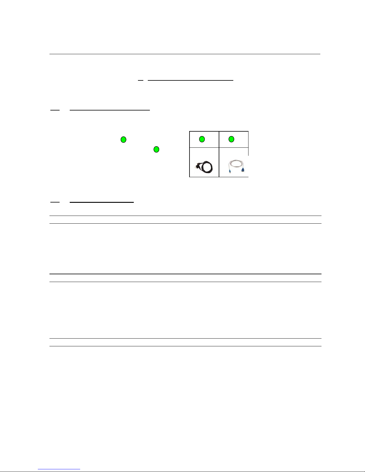
2.1. List of included accessories
Check that all elements are present in the box:
-Power supply cable
-Serial/USB cable and it’s mini-CD
-1 CD-ROM (included in the leaflet)
-1 satisfaction survey
2.2. General specifications
RDS/RBDS signal
Sub-carrier 57khz (+- 3Hz)
Phase adjustment +- 180° in 6° steps
Output level -60dBu to 0dBu in 1dB steps or (depending on set up) 2,5 to 3199mVcc / 1mv
Spectral purity conform to CENELEC
Bandwidth +-2,4kHz (60dB)
SYNC/MPX connector input signal
Connector asymmetrical BNC
Max nominal input signal +12dBu
Peek input signal 18dBu allowed
Max input signal +22dBu
Pilot frequency 19000Hz +- 3Hz
Recommended 19000Hz +- 1Hz
Retransmission gain +-1dB DC-100kHz
RDS output signal
Connector asymmetrical BNC
Output impedance 100 ohms
Typical load impedance >500 ohms
<100pF
THD <0,02% (f=10kHz)
THD <0,04% (f=57kHz)
2
1 2
1

FMB10 User’s Manual Edition 06/2005
___________________________________________ Page 5 _____________________________________________
Audemat-Aztec SA – Audemat-Aztec INC
WEB: www.audemat-aztec.com - e-mail: [email protected]
Communication interfaces
Set up port COM0 RS232/TTL
EBU port COM0 RS232/TTL
speed (baud) 1200 to 9600
parity even, odd, none
TA control yes by external switch.
.
Other data
Temperature (operating) 0° to 55°
Storage -40° à 80°C
Humidity class F DIN40040
EMC CENELEC EN5022
Generic standards
EMC Immunity 10V/m
Supply voltage 115V / 230V
Tolerance on supply voltage +-20%
Supply frequency 45-65 Hz
Power supply filter yes (Schaffner)
Fuse 250mA / 500mA
Power consumption 15VA approx.
Weight 2100g without packaging and cable
Length/width 19" (483mm)
Height 1U (44,5mm)
Depth 220mm
FMB10 User’s Manual Edition 06/2005
___________________________________________ Page 6 _____________________________________________
Audemat-Aztec SA – Audemat-Aztec INC
WEB: www.audemat-aztec.com - e-mail: [email protected]
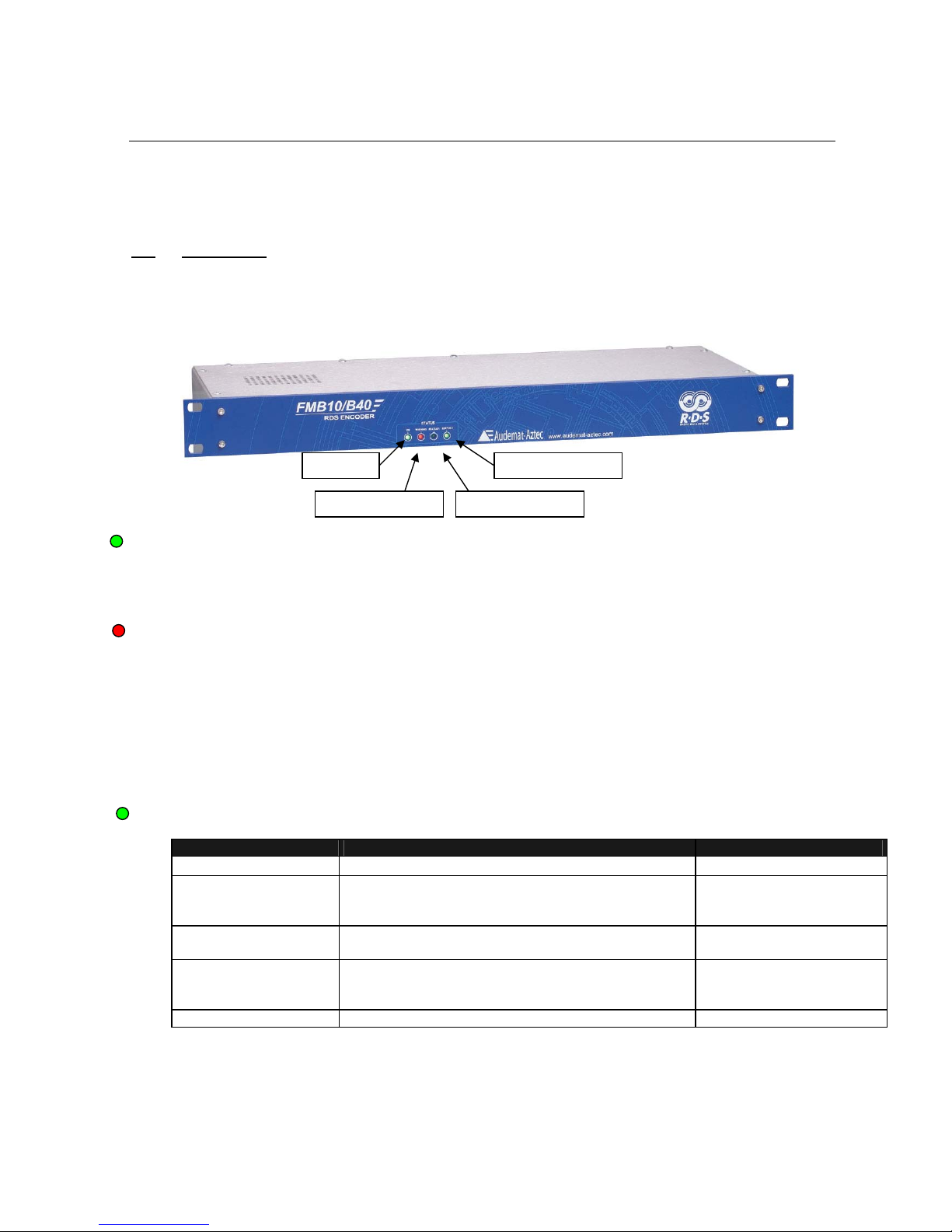
2.3. Front panel
Green LED "POWER"
On Encoder switched on
Off Encoder not lit. If the switch is on 1, check the fuse
"WARNING" :
Flashing: indicates that the BYPASS" function» is active
Continuously or almost continuously on: indicates that the encoder detects a warning.
Off: The configuration of the encoder is credible, the
encoder does not detect anything abnormal.
Other cases: (transient lighting) This led also lights on power up, whilst reading the
parameters in
non volatile memory : if the led remains lit, the encoder
is unable to initialise correctly.
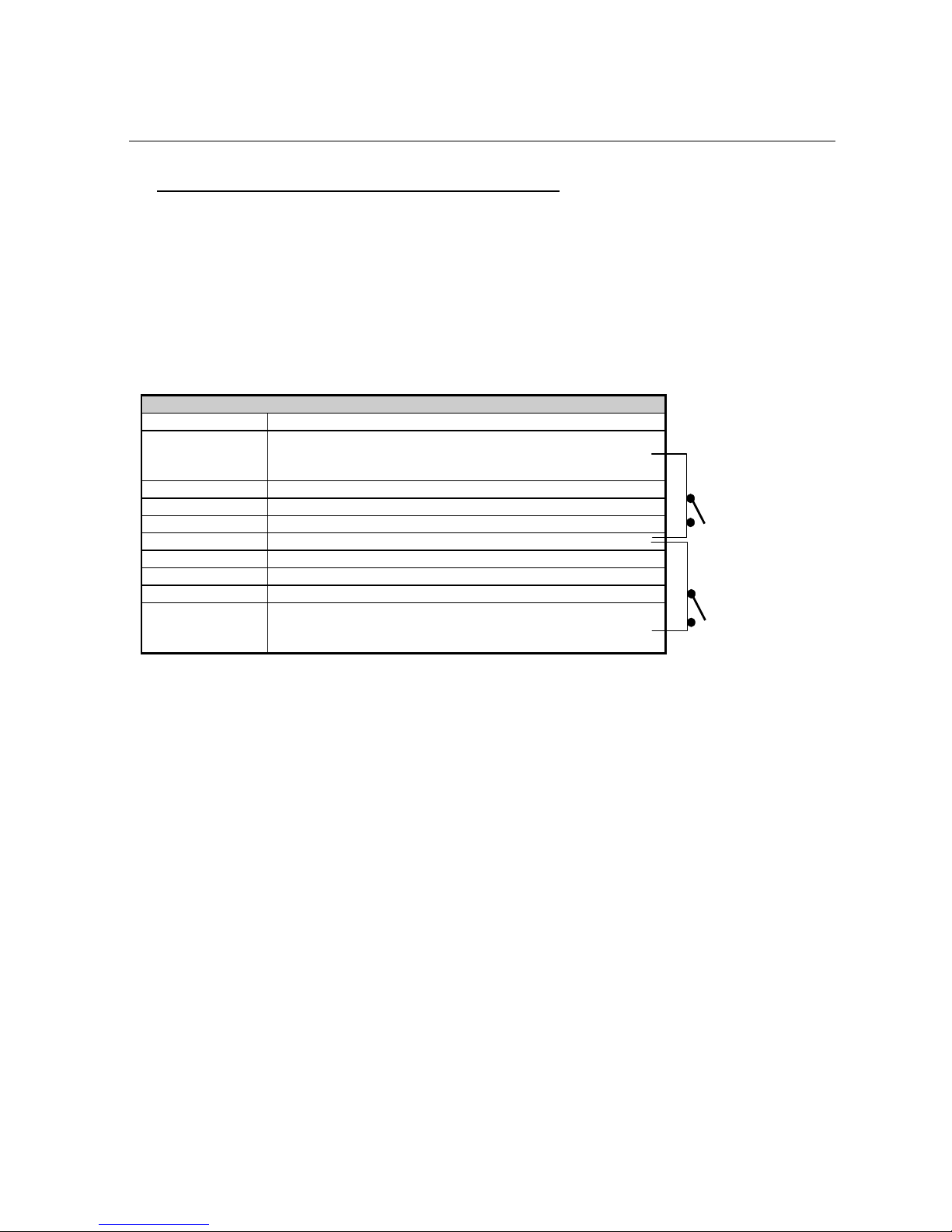
GREEN LED "STATUS 1”:
LED "STATUS1 Synchronisation Mode EBU
Off Encoder synchronised with the internal clock not selected
1 flash/second
19 kHz synchronisation signal detected and
synchronisation possible if SYNCHRO = EXT or
SYNCHRO = AUTO
not selected
several flashes /
second
Synchronisation state not visible. Selected but not yet active
1 extinction flash /
second
19 kHz synchronisation signal detected and
synchronisation possible if SYNCHRO = EXT or
SYNCHRO = AUTO
selected and active
On Encoder synchronised with internal clock selected and active
LED ON
LED WARNING LED STATUS1
LED STATUS2

FMB10 User’s Manual Edition 06/2005
___________________________________________ Page 7 _____________________________________________
Audemat-Aztec SA – Audemat-Aztec INC
WEB: www.audemat-aztec.com - e-mail: [email protected]
Green Led "STATUS 2" :
Fully off or fully on: The CPU of the RDS encoder is not running, or is running incorrectly.
1 flash per second: Code PI1 or NPROG1 (programme codes n°1) being broadcast.
2 flashes per second: Code PI2 or NPROG2 (programme codes n°2) being broadcast.
More than 4 flashes per second: Code TA activated to 1, being broadcast.
2.4. Rear panel
¾IEC connector : main power switchable from 230 to 115 VAC
¾SUB-D type 9 pin female : COM0 RS-232 port
¾BNC : OUT
= RDS or MPX output signal
¾BNC : SYNC/MPX IN = synchronisation input and/or composite ‘multiplex’ signal input
1
1
2
2
3
3
4

FMB10 User’s Manual Edition 06/2005
___________________________________________ Page 8 _____________________________________________
Audemat-Aztec SA – Audemat-Aztec INC
WEB: www.audemat-aztec.com - e-mail: [email protected]
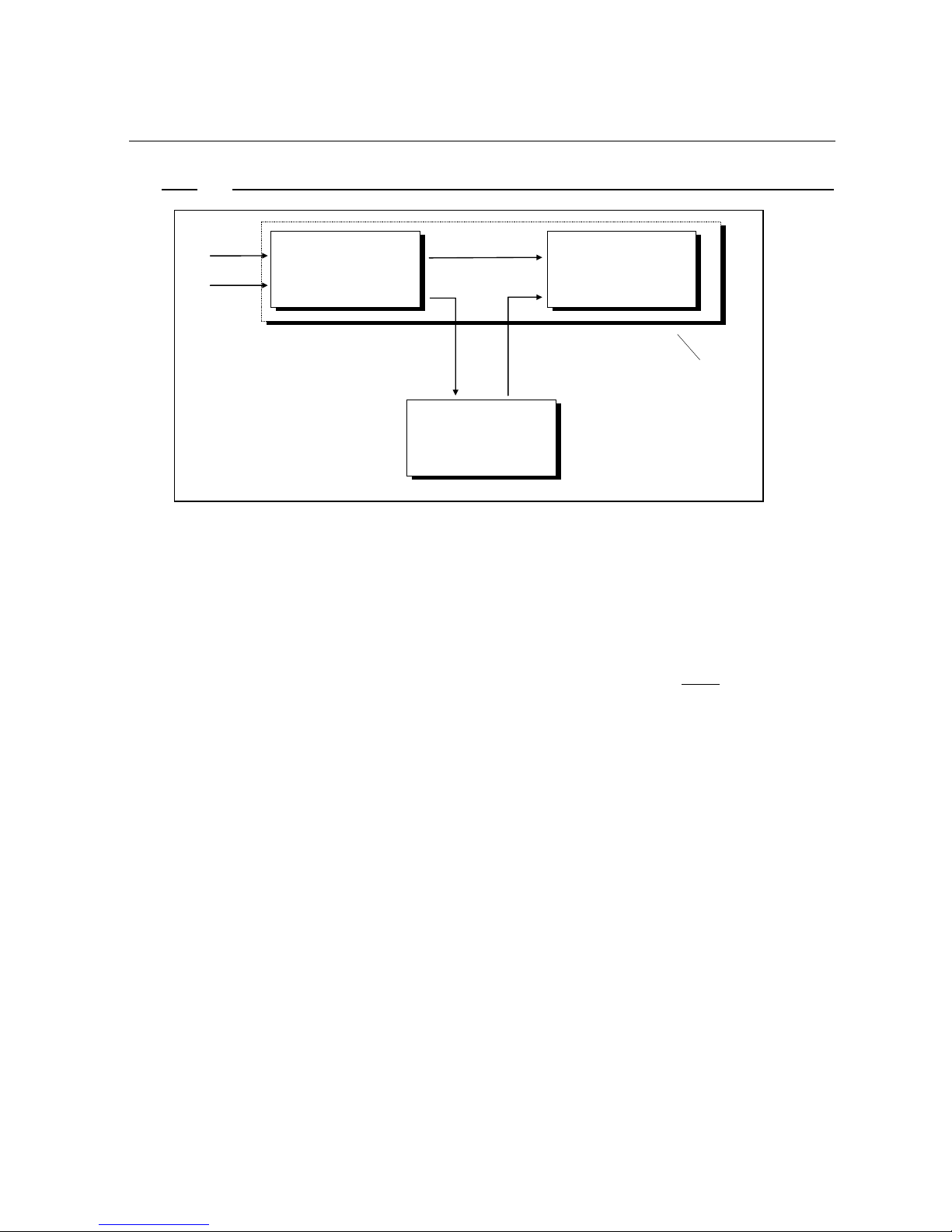
2.5. Internal layout
D
A
J1
PLL
Rela
y
Rela
y
EXT
INT
A
UTO
J2
D
A
12bits 12bits
RDS digital
Synthesiser
CPU
RAM
(data)
EPROM
(code + data)
EEPROM (set up + parameters)
SYNCHRO / MPX
Input
Output
RDS (& MPX)
COM0
X
S1
X
S2
J5 J4
FMB40 extension connector
RX
TX
"ON" Led
"WARNING" Led
"STATUS1" Led
"STATUS2" Led
J3
Power supply
+5V
+15V
-15V
RS232 DCE
FMB10 RDS
encoder PCB
FMB10 User’s Manual Edition 06/2005
___________________________________________ Page 9 _____________________________________________
Audemat-Aztec SA – Audemat-Aztec INC
WEB: www.audemat-aztec.com - e-mail: [email protected]
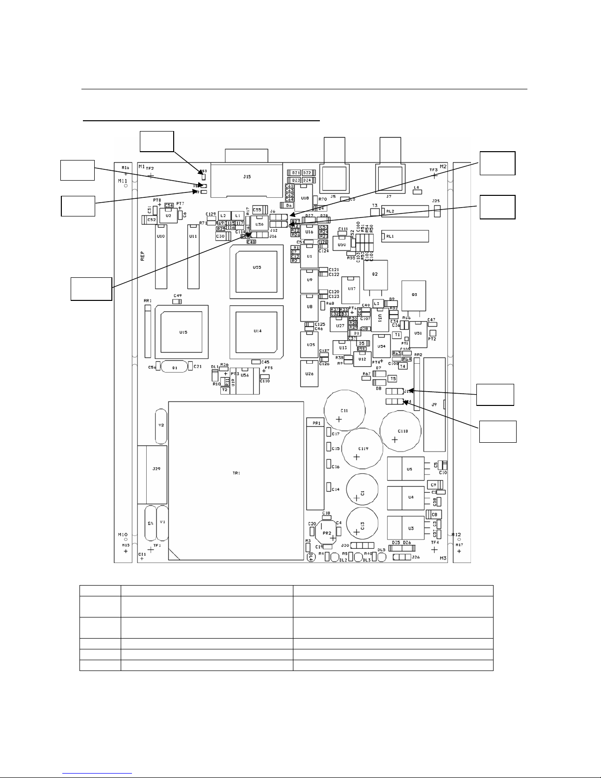
2.6 FMB10 Board and configuration of the jumpers
LOOP THROUGH SIDE CHAIN
Jumper between 1 and 2 Jumper between 2 and 3
J1 FMB10 OFF => retransmission of MPX
IN signal to MPX OUT
FMB10 OFF => no retransmission of MPX IN
signal to MPX OUT
J2 FMB10 ON => retransmission of MPX IN
signal to MPX OUT
FMB10 ON => no retransmission of MPX IN
signal to MPX OUT
J3 MPX OUT = RDS MPX OUT = MPX IN + RDS
J4 Operation as FMB40 Operation as FMB10
J5 Operation as FMB40 Operation as FMB10
J1
J2
XS1
XS2
XS3
2
J3
J4
J5
FMB10 User’s Manual Edition 06/2005
___________________________________________ Page 10 _____________________________________________
Audemat-Aztec SA – Audemat-Aztec INC
WEB: www.audemat-aztec.com - e-mail: [email protected]
2.7 “COMO” port : RS232 and auxiliary signals, rear panel
•permits the configuration of the RDS encoder parameters, via a PC or terminal. Several protocols are
possible including ASCII for the FMB10 encoder (see relevant chapters.
•For the FMB10 encoder : COM0 permits the remote control of the encoder for example via a satellite or
earth link
•For the FMB10 encoder, COM0 permits the transmission of dynamic RDS information (Free format
RDS groups etc...)
RS232 PORT "COM0" (FMB10 encoder)
Pin Signal
1 According to the configuration of the strap "XS1" to be
soldered, this pin permits the switching of the TA parameter
with an external switch.
2 TX of RDS encoder (DCE)
3 RX of RDS encoder (DCE)
4 connected to pin 6 of the same connector
5 RDS encoder ground
6 connected to pin 4 of the same connector
7 connected to pin 8 of the same connector via buffer
8 connected to pin 7 of the same connector via buffer
9 According to the configuration of XS2 to be soldered, this pin
permits the switching between PI1 and PI2, PS1 and PS2,
with an external switch.
ON:
TA=1
OFF:
TA=0
ON:
PI2/PS2
OFF:
PI1/PS1

FMB10 User’s Manual Edition 06/2005
___________________________________________ Page 11 _____________________________________________
Audemat-Aztec SA – Audemat-Aztec INC
WEB: www.audemat-aztec.com - e-mail: [email protected]
3. GETTING CONNECTED
3.1 Connection
¾Connect the equipment to the sector by using the power supply cable.
¾Connect the computer to the “COM 0” with the serial USB/cable
¾Connect the BNC cable of the stereo encoder with the MPX IN of the RDS encoder
¾Connect the MPX IN or emettor’s RDS with MPX OUT of the RDS encoder
¾Light the encoder thanks to the swith on the rear panel
1
2
2
1
3
3

FMB10 User’s Manual Edition 06/2005
___________________________________________ Page 12 _____________________________________________
Audemat-Aztec SA – Audemat-Aztec INC
WEB: www.audemat-aztec.com - e-mail: [email protected]
3.1.1. To connect the FMB10 encoder to the transmission installation : “loop through”
¾The FMB10 encoder is inserted between the Stereophonic encoder and the transmitter (pilot): this is
the most frequent set up.
¾The synchronisation of the RDS encoder is done by extracting the 19 KHz pilot signal contained in the
signal supplied by the stereophonic encoder to the RDS encoder "sync/mpx" input.
IMPORTANT: in this configuration, place "J1" and "J2" of the FMB10 PCB so as to ensure the retransmission,
of the composite 'multiplex' signal applied to the input of the RDS encoder in all cases.
STEREOPHONIC
ENCODER
Left audio
Left audio
FM PILOT
TRANSMITTER
Pilot MPX
input
FMB10
FMB10
"sync/multiplex" input
FMB10 output
FMB10 User’s Manual Edition 06/2005
___________________________________________ Page 13 _____________________________________________
Audemat-Aztec SA – Audemat-Aztec INC
WEB: www.audemat-aztec.com - e-mail: [email protected]
3.1.2. To connect the FMB10 encoder to a RDS or SCA input of the pilot transmitter : side chain
¾This configuration is less common but more "professional". It uses the input of the FM pilot provided for
this reason.
The synchronisation of the RDS encoder is done by applying a 19 KHz clock (usually available at an
auxiliary output of the stereophonic encoder) to the RDS encoder "sync/mpx" input.
If no 19 KHz signal is available on the stereo encoder output, apply the multiplex signal directly to the
"sync/mpx" input of the RDS encoder.
¾It is advised, in this set up to configure "J1" and "J2" of the RDS Silver Encoder PCB to inhibit the "BYPASS"
function in all cases.
STEREOPHONIC
ENCODER
Left audio
Left audio
FM PILOT
TRANSMITTER
Pilot MPX
input
FMB10
FMB10
"sync/multiplex" input FMB10 encoder
output
Stereo encoder
19KHz output
Pilot "SCA" or
"
RDS
"
input
In some installation, the
stereophonic encoder is
integrated with the pilot
transmitter.
FMB10 User’s Manual Edition 06/2005
___________________________________________ Page 14 _____________________________________________
Audemat-Aztec SA – Audemat-Aztec INC
WEB: www.audemat-aztec.com - e-mail: [email protected]
3.2 Installation of the FMB10 encoder’s SOFTWARE (see more details in chapter 4)
¾Load the FMB10 encoder CD-ROM software, double-click on the icon “Audemat-Aztec” and select “FMB10
“in the combo-list to launch the installation program.
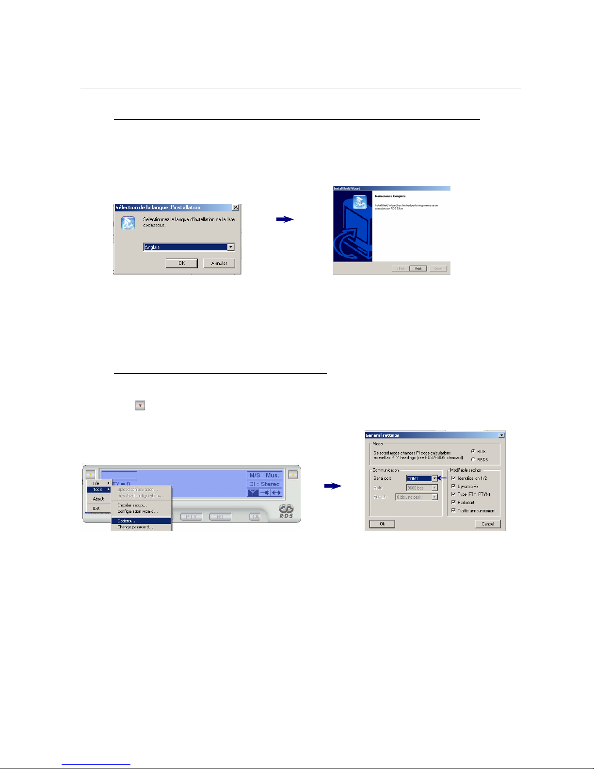
¾Select the installation language and continue the installation assistant until the end.
Check: “Yes, I want to restart my PC now” before ticking “Finish”.
¾Once the PC is restarted, launch the FMB10 encoder’s software by double-clicking on the short-cut
placed on the desk:
3.3 Communication between software and FMB10
The software tries to connect automatically: if the encoder is not detected, follow this process:
In the menu ( ), click on « tools » then « options… » and select the serial port:
To select the right “Com Port” :
To find out what port number is being used (physical or virtual), click right on “my computer” to select
“properties/hardware/hardware wizard”. Then click on « Ports » to see the “com ports” installed on the PC
and select “USB-to-serial” to see the “COM PORT” used (if it’s COM1, select COM1 in the serial port).
Click on “OK” to validate the options. The software establishes a communication by using the selected serial
port.

FMB10 User’s Manual Edition 06/2005
___________________________________________ Page 15 _____________________________________________
Audemat-Aztec SA – Audemat-Aztec INC
WEB: www.audemat-aztec.com - e-mail: [email protected]
3.4 Encoder’s configuration (basic & advanced)
Basic : In the menu ( ) click on « Tools » then « configuration wizard… ».
Follow the wizard indications necessary to the encoder configuration.
Advanced : To set up an “advanced” configuration, go to the menu ( ), select “tools/encoder setup” and enter your main
parameters.
This visual shows that the connection has been established:
Connected non-connected
In case of failure, check that the encoder is well lit and that the connections are correct. Then click on « F5 » on you
r
PC to relaunch the connection. If there is still a problem, start again stage 4 and change the serial port in
« Options… ».
FMB10 User’s Manual Edition 06/2005
___________________________________________ Page 16 _____________________________________________
Audemat-Aztec SA – Audemat-Aztec INC
WEB: www.audemat-aztec.com - e-mail: [email protected]
4 INSTALLATION OF THE FMB10 CONTROL SOFTWARE
This software has been designed for operating and configuring FMB10.
Its interface comprises:
¾a display indicating the main parameters of the encoder generated RDS data.
¾a set of buttons giving access to the encoder’s current operating functions.
¾a button which enables the software’s main menu to be accessed. A password can protect
these functions and allow only qualified technical personnel to access.
The software has been designed for running with the encoder by means of an RS232C link so as to program it
in real time when changing parameter values. It can also save the configurations created in file form: this
enables an encoder to be quickly reprogrammed in a given configuration.
The software is supplied on a CD-Rom which contains an installation program as well as this user’s manual in
file form, readable using Adobe software: Acrobat Reader®.
4.1 Installation
4.1.1 Software environment
The software is intended for Microsoft WINDOWS 9x, NT 4.x, 2k or XP. The user will make sure that his/her
environment has the appropriate software and versions by referring to equipment and software manuals.

FMB10 User’s Manual Edition 06/2005
___________________________________________ Page 17 _____________________________________________
Audemat-Aztec SA – Audemat-Aztec INC
WEB: www.audemat-aztec.com - e-mail: [email protected]
4.1.2 Computing configuration
The following table indicates the computer system configuration which is necessary – or recommended – for the
software’s optimum running.
Windows 9.x Windows NT 4.x (SP6) Windows 2k (SP3) XP
Processor Pentium 100MHz Pentium 233MHz Pentium 300Mhz
RAM memory capacity 16 Mo 64Mo 128Mo
Required hard disk space 80 Mo 80 Mo 80 Mo
4.1.3 Installation procedure
Proceed as follows to install software:
¾Before starting installation, close any application which may be running.
¾Insert the CD-Rom into the computer.
¾If the Auto-run mode has not been disabled, the installation program will start up automatically.
Otherwise, select Run… from the Start menu and enter the following command (supposing that D
represents the CD-Rom drive):
D:\Setup.exe
¾A window requests the user to choose the language used by the program. Select the preferred
language, and then click OK to continue: the installation assistant’s home window is displayed.
¾Click on Next to proceed to installation.
¾Once installation is complete, a window will propose launching the application automatically: validate
this option if desired then click on Finish so as to quit the installation program.
4.1.4 De-installation procedure
Proceed as follows to delete the FMB10 encoder’s control program:
¾Make sure that this program is not running.
¾Select 'Parameters – Configuration panel' from the 'Start' menu, then click twice on the icon:
Add/Delete programs.
¾Select 'FMB10 Encoder' from the displayed list and click on Modify/Delete.
¾The automatic procedure is initialized.

FMB10 User’s Manual Edition 06/2005
___________________________________________ Page 18 _____________________________________________
Audemat-Aztec SA – Audemat-Aztec INC
WEB: www.audemat-aztec.com - e-mail: [email protected]
4.2 Quick start
4.2.1 Program launching
After having installed the program, follow this procedure in order to be acquainted with its use:
¾Link the FMB10 encoder to the computer’s COM port using an RS232 cable. Computers equipped
with only a USB interface will also need a USB/RS232 adapter.
¾Start the encoder.
¾Start up the program:
- either by clicking twice on the FBM10 icon.
- or by selecting Programs from the Start menu then clicking on FMB10 in the
AUDEMAT-AZTEC folder.
¾The program now starts up and attempts to establish the link with the encoder by using the COM
port defined in the options (COM1 by default): the state of the connection is displayed:
- : the dialog has been correctly passed on and the link established.
- : the dialog has not been established: check the connection and/or the
communication parameters then re-launch the procedure by pressing the F5 key.
¾Once connection has been established, the current configuration is loaded using the encoder and
the main parameters are displayed: PS and Radio text zones present a display simulation of these
RDS signals on a receiver.
4.2.2 Software use
There are two ways of using the software:
¾Operating mode: it enables direct access to the basic parameters using the buttons located at the
bottom of the window.
¾Advanced mode: it gives access to all the software’s functions using the Main menu button located
on the top left of the window. A password can protect the use of this mode.
For any information concerning RDS standards, please consult the following documents:
•CENELEC Standard EN50067: 1998.
•The new RDS IEC 62106: 1999 draft standard.
•UNITED STATES RBDS STANDARD: April 9, 1998.

FMB10 User’s Manual Edition 06/2005
___________________________________________ Page 19 _____________________________________________
Audemat-Aztec SA – Audemat-Aztec INC
WEB: www.audemat-aztec.com - e-mail: [email protected]
4.3 Function details
4.3.1 Main window
This consists of a zone displaying the encoder’s main parameters and the command buttons.
Active button wording appears in dark red:
When the mouse’s cursor goes over an active button, its wording appears in bright red:
When a function is disabled or inaccessible, the corresponding button appears in grey:
When the mouse cursor stays above a button or a display parameter zone, an explanation message is
displayed.
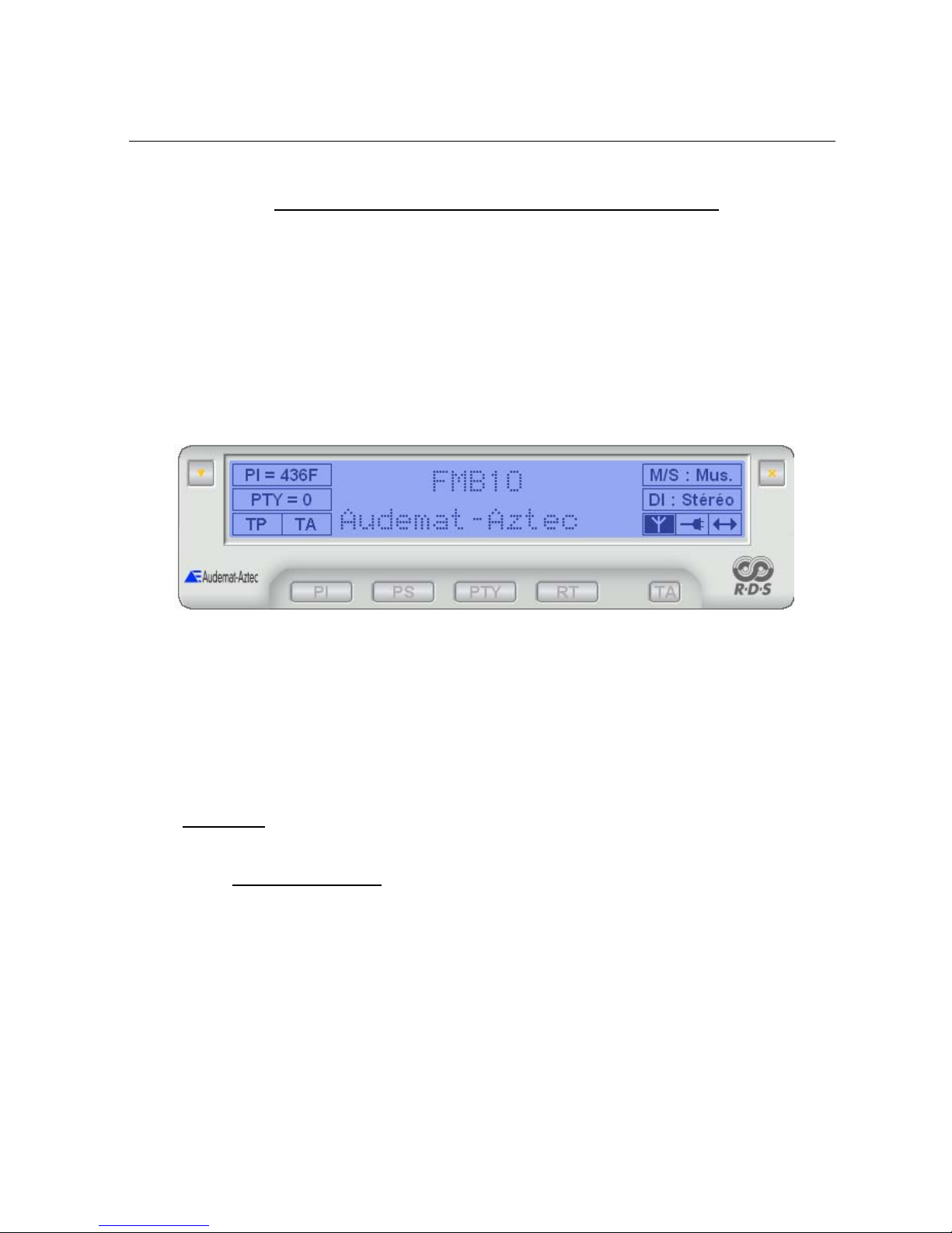
4.3.1.1 Description of display
The upper part of the main window is occupied by a display zone which reproduces an LCD type of displayer.
The central part is reserved for alpha-numerical indications:
•PS (Programme Service name): this is the name of the received program, displayed on all
RDS receivers. This zone also displays the Dynamic PS when this functionality is active (see
paragraph ). This zone has 8 characters.
•RT (Radio text): a text message of a maximum of 64 characters destined for receivers
equipped with an appropriate displayer (usually home receivers). This zone has 16 characters.
When this information is dynamic (Dynamic PS, Radio text), the display is a simulation of RDS data transmitted
by the encoder (timing, groups of characters …). It is not, in any way, a question of an acquisition of actual
FMB10 User’s Manual Edition 06/2005
___________________________________________ Page 20 _____________________________________________
Audemat-Aztec SA – Audemat-Aztec INC
WEB: www.audemat-aztec.com - e-mail: [email protected]
encoder transmitted data: especially, the object is not to try to check synchronism with the display obtained on
an RDS signal analyser in real time.
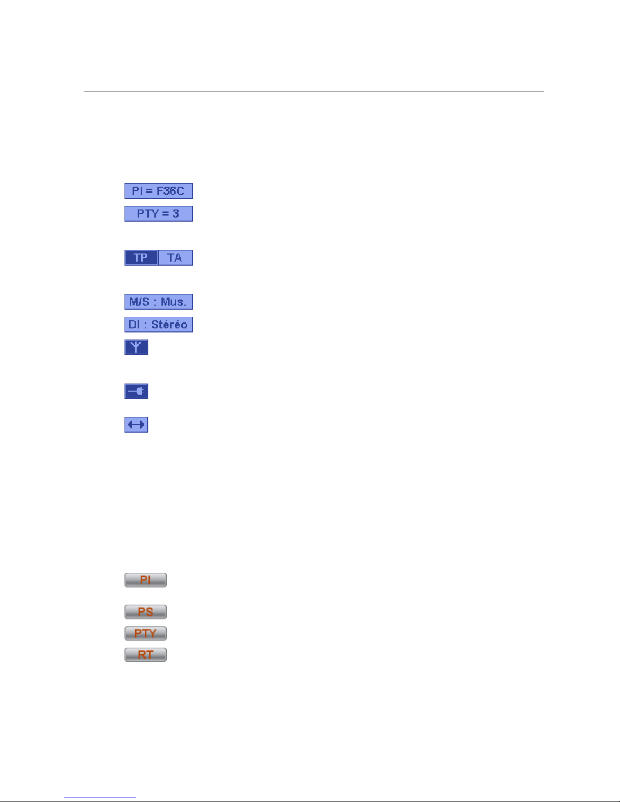
Right and left parts of the displayer are used to present static or temporary parameters. From top to bottom and
from left to right can be found the following:
: PI code display zone (Program Identification) being broadcast.
:PTY code display zone (Program Type). When the mouse cursor stops for a moment
on this zone, code signification is indicated on light background. If a PTYN (Program TYpe name) has
been configured, its contents are displayed following the PTY.
: Current state of control signals of Info Trafic system (Traffic Programme, Traffic
Announcement). Dark text on light background indicates a value of 0(here TA), and, vice versa, light
text on dark background indicates a value of 1(here TP).
: State of MS communication code (Music / Speech).
: State of bit 0 (Mono/Stereo) of DI code (Decoder Identification).
: State of encoder output: indicates if an RDS signal is in fact present at encoder output (signal’s
Stop/Start parameter, see paragraph 4.3.2). Dark background indicates the presence of an output
signal.
: State of connection with the encoder. Dark background indicates that the connection has been
established and that any parameter modification will be transmitted to the encoder.
: Current encoder communication indicator when background is dark. This indication is
momentary.
4.3.1.2. Description of buttons
The lower part of the window contains a series of buttons for currently operating the encoder: one click on one
of these buttons (excepting TA) will display a window enabling corresponding parameter(s) to be modified.
These windows have 2 buttons: the Send button enables the encoder to be programmed with the considered
parameter’s new value; the Close button enables the window to be automatically closed again.
From left to right:
: enables station identification parameters to be toggled (PI + PS) between the two actions
maintained by the encoder.
: enables the Dynamic PS text to be modified (See for more details on this functionality).
: enables both the transmitted PTY code and the PTYN message text to be modified.
: enables the Radio text message to be modified. If the Radiotext is stopped, this button is
not active (cf 4.3.2 Radiotext).enables the Radio text message text to be modified.
Table of contents
Popular Media Converter manuals by other brands


Addonics Technologies
Addonics Technologies ADSAU3RM user guide

Metrum Acoustics
Metrum Acoustics PAVANE user manual

Marshall Electronics
Marshall Electronics BC-0909-DA user guide

Mission
Mission 778X user manual

Optical Systems Design
Optical Systems Design OSD2010 Operator's manual

Cary Audio Design
Cary Audio Design CD 200 operating manual