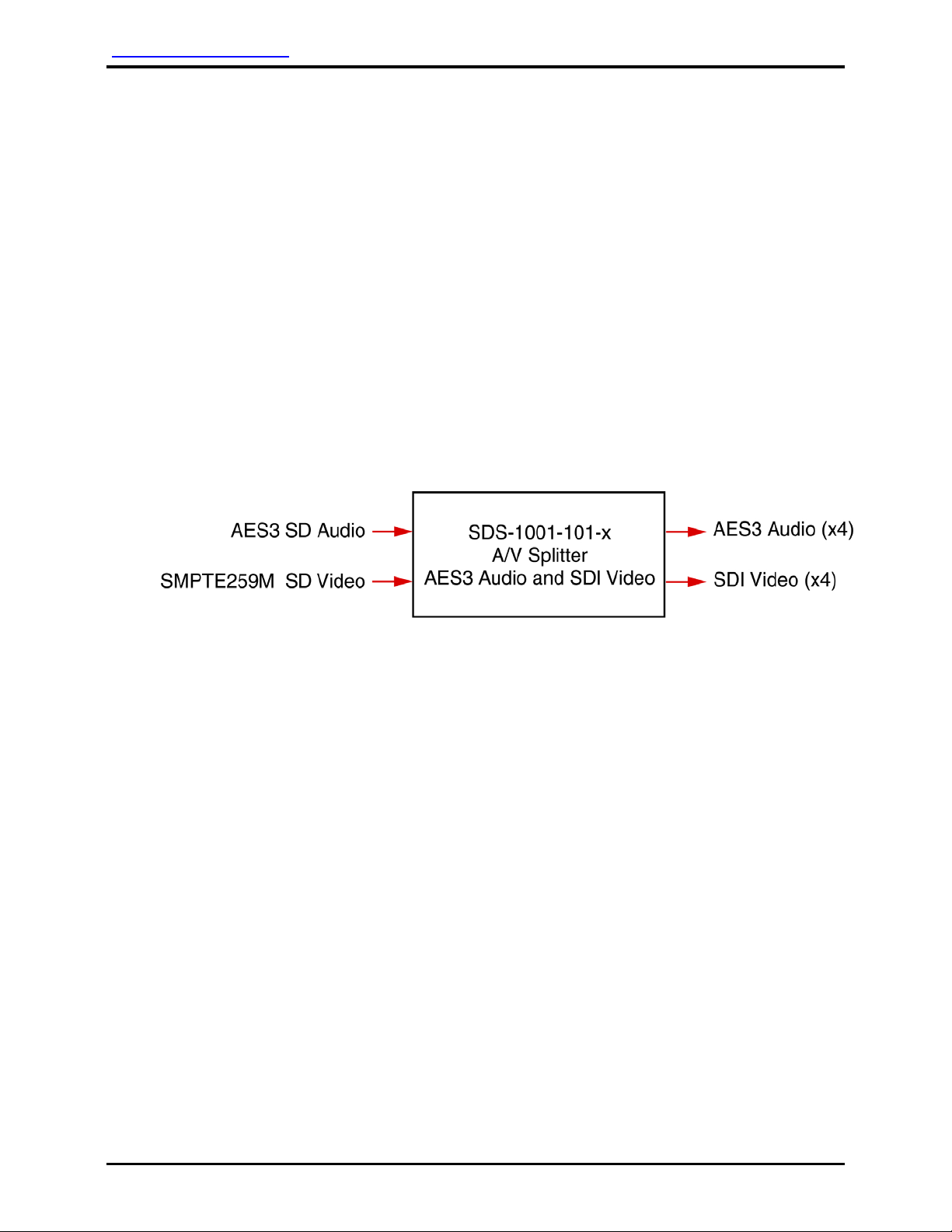
Audio International, Inc. SDS-1001-101-x Installation Manual
Document #540306, Rev IR, 04/2005 Page 6 of 12
3.4 Wiring Requirements
3.4.1 Introduction
The installing agency shall supply and fabricate all external cables
and connectors. The length and routing of external cables should
be carefully studied and planned before attempting installation of
the equipment. Allow adequate space for installation of cable and
connectors.
3.4.2 Power and Ground Wires
Power and ground connections are recommended to use 22 AWG,
minimum, wiring in accordance with MIL-W-22759 or equivalent.
3.4.3 Source Wires
Source input digital audio connections are recommended to use 22
AWG, minimum, shielded twisted pair cabling as necessary in
accordance with NEMA WC 27500 or equivalent.
3.4.4 SDI Video
SDI video connections are recommended to use shielded coaxial
cable V76261 from PIC Wire and Cable. Cable length limitations
are 50 meters with up to four (4) interconnects permitted, as long
as the connectors do not create in-line impedance (example - the
50 meter video cable can be broken up into five 10 meter
segments). In-line connectors must be rated the same
characteristic impedance; it must be designed for the cable and
installed properly. In the case of V76261 cable, the characteristic
impedance is 75 ohms. For longer cable runs, a transition to RG59
cable, using BNC connectors, can be made.
3.4.5 AES3 Serial Digital Audio
All digital audio wire connections must be twisted shielded cable
with the shield properly grounded to the dedicated pin at the source
end to the dedicated pin at the load end. Twisted shielded cable
shall be 22 AWG (minimum) for digital audio signals and shall be in
accordance with NEMA WC 27500 or equivalent. Cable
impedance must be 110 Ω+/- 10%.