Audio international VCP-014-01-x User manual

Audio International, Inc. VCP-014-0x-x Installation & Operation Manual
Document #540097, Rev. B, 09/2001 Page 1 of 21
Document Revision History
Rev. Level Date Description
IR 03/1998 Initial Release
A 08/2000 ECN #4543
B 09/2001 Include VCP-014-05-x
Reference Documents
Document # Description
522022 Rev A1 VCP-014-0x-x Outline Drawing
522071 Rev A Outline, VCP-014-02-x,
VCP-014-03-x
522268 Rev IR VCP-014-04-x Outline Drawing
523322 Rev IR VCP-014-05-x Outline Drawing
Service Bulletin List
Service
Bulletin # Subject Manual
Revision Revision
Date
Table of Illustrations
PROPRIETARY INFORMATION NOTICE: Despite any other copyright notice, this document and
information disclosed herein contains confidential, proprietary designs owned by Audio
International, Inc. Neither this document nor the data contained herein shall be reproduced, used,
or disclosed to anyone without the written authorization of Audio International, Inc.
Section # Subsection # Description Page #
I 6.2 Typical Application 6
II 9.0 Reference Drawings 12-17

Audio International, Inc. VCP-014-0x-x Installation & Operation Manual
Document #540097, Rev. B, 09/2001 Page 2 of 21
Table of Contents
Section Description Page
I General Information……………………………………………… 3
1.0 Introduction…………………………………………………………. 3
2.0 Purpose of the Equipment………………………………………… 3
3.0 Operational Features……………………………………………… 3
4.0 Optional Equipment……………………………………………….. 4
5.0 Technical Specifications………………………………………….. 4
6.0 Application………………………………………………………….. 5
II Installation……….………………………………………………… 7
1.0 Prior to Installation…………………………………………………. 7
2.0 Unpacking and Inspection………………………………………… 7
3.0
Cautions &Warnings……………………………………………… 8
4.0 Wiring Requirements……………………………………………… 9
5.0 Physical Characteristics…………………………………………... 9
6.0 Electrical Characteristics…………………………………………. 10
7.0 Post-Installation Test……………………………………………… 11
8.0 Troubleshooting Guide……………………………………………. 11
9.0 Reference Drawings………………………………………………. 12
III Operation….……………………………………………………….. 18
1.0 General Information……………………………………………….. 18
2.0 To Load a Video Cassette into the Tape Slot…………………... 19
3.0 Operating Instructions…………………………………………….. 20

Audio International, Inc. VCP-014-0x-x Installation & Operation Manual
Document #540097, Rev. B, 09/2001 Page 3 of 21
VCP-014-0x-x
Multi-Standard Video Cassette Player
SECTION I –GENERAL INFORMATION
1.0 Introduction
This manual contains information for the proper installation and operation of
Audio International’s (AI) Multi-Standard Video Cassette Player,
Model # VCP-014-0x-x. The “-0x”in the model number designates the specific
configuration of the unit. The “-x”in the model number designates the type of
connector utilized; “-1”= Positronic and “-2”= D-Subminiature. Also included are
mechanical and electrical characteristics of the unit.
2.0 Purpose of the Equipment
2.1 The VCP-014-0x-x is a video cassette player specifically designed to meet
the special requirement of aircraft use. The unit plays NTSC, PAL, and
MESECAM video formats. In addition, the VCP-014-0x-x is capable of
defaulting to the video input source when the tape is off.
2.2 The VCP-014-0x-x can be mounted in a cabinet or bulkhead. A unique
strapping feature allows up to four (4) similar devices to be used in the
same system at the same time while maintaining independent control.

Audio International, Inc. VCP-014-0x-x Installation & Operation Manual
Document #540097, Rev. B, 09/2001 Page 4 of 21
3.0 Operational Features
Key features of the VCP-014-0x-x:
q
DO-160C tested
q
Operates directly from +28 VDC
q
Front panel controls
q
Optional infrared remote controllable
q
Frequency response of 20 Hz to 20 kHz
q
Plays NTSC, PAL, and MESECAM formatted video cassettes
q
High quality standard VHS
q
High fidelity stereo sound
q
Audio output level +1 to +5 VRMS into 600 , internally adjustable
q
Video output level +1 V(p-p) into 75
q
Standard plating options for front bezel
q
No cooling requirements
q
Easy to mount and connect
q
AI proprietary RS-485 data bus compatible
q
Compact, lightweight package
4.0 Optional Equipment
The VCP-014-0x-x can be optionally controlled by infrared remote or AI’s touch
screen panel. Digital codes allow the unit to interface with an infrared handheld
remote via an infrared receiver, IFR-9A or IFR-485. Multiple units can be
controlled independently using available programming pins. Playback options
with remote or touch screen include visual search, pause, play, stop, fast-
forward, and rewind.
Contact your AI representative for details
5.0 Technical Specifications
Physical Specifications
Housing Aluminum
Dimensions
(l x w x h)
11.8" x 14.0" x 3.8"
29.97cm x 35.56cm x 9.65cm
Note: The VCP-014-04-x has a width of 13.8"
(35.1 cm)
Weight 8.4 lb / 3.81 kg

Audio International, Inc. VCP-014-0x-x Installation & Operation Manual
Document #540097, Rev. B, 09/2001 Page 5 of 21
Power 1 A @ +28 VDC
Operating Voltage Range +18 to +32 VDC
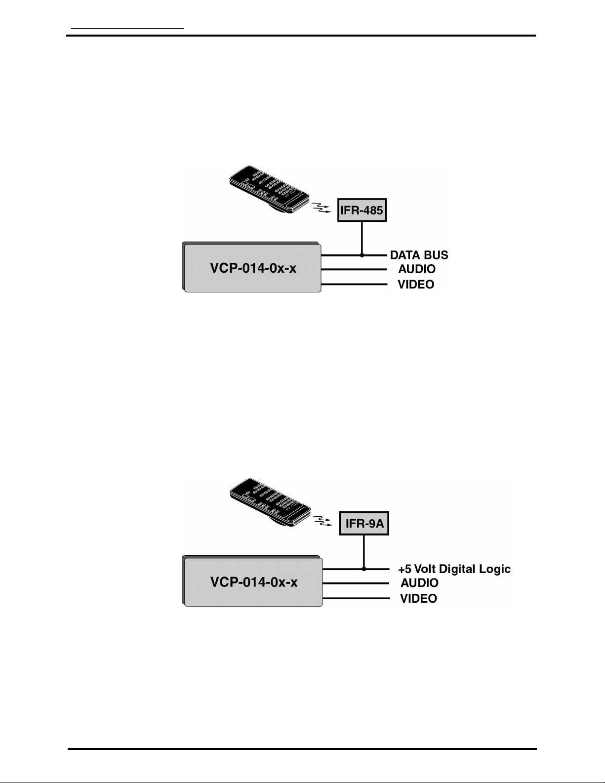
Data Bus Type AI Proprietary RS-485
Audio Frequency Response 20 Hz to 20 kHz
Audio Output 2 VRMS into 600
(factory preset)
Audio S/N > 42dB (NOMINAL)
Dynamic Range > 90dB
Video Output +1V(p-p) into 75
Horizontal Line Resolution NTSC-525
PAL, & MESECAM
Video Heads 4
Electrical
Infrared Signal Input +5 V digital logic level
6.0 Application
6.1 Introduction
Five (5) specific VCP-014-0x-x model numbers are available.
6.1.1 The VCP-014-01-x is a multi-standard video cassette player that
plays all versions of NTSC, PAL, and MESECAM video cassettes.
In addition, this player is capable of defaulting to an input video
source when the playback options are not in use.
6.1.2 The VCP-014-02-x has the same features and capability as the
VCP-014-01-x. However, the VCP-014-02-x has a chamfered back
edge on the casing for ease in bulkhead mounting.
6.1.3 The VCP-014-03-x has the same features and capability as the
VCP-014-01-x. However, the VCP-014-03-x has an added feature
of an internal modified spring to allow for vertical mounting of the
unit.
6.1.4 The VCP-014-04-x has the same features and capability as the
VCP-014-01-x. However, the VCP-014-04-x has the added feature
of a flush faceplate for ease in “cabinet”mounting of the unit; there
is no ‘lip’around the front bezel of the unit. The switch panel is
located to the left of the unit’s cassette opening.
6.1.5 The VCP-014-05-x has the same features as the VCP-014-01-x,
except the switch panel is centered under the cassette opening.
The lip on the ‘Top’and ‘Bottom’edges are not flush.

Audio International, Inc. VCP-014-0x-x Installation & Operation Manual
Document #540097, Rev. B, 09/2001 Page 6 of 21
6.2 Typical Application
6.2.1 This system is fully compatible with Audio International’s proprietary
RS-485 digital data bus system. It can be configured for IR remote
control utilizing AI’s remote control unit AI-RC1-17xxxx and
IFR-485.
6.2.2 The unit can also be configured for IR remote control utilizing AI’s
remote control unit AI-RC1-17xxxx and IFR-9A. This following
configuration utilizes a +5 VDC digital logic level for activation of
infrared commands. Connection to multiple IFR-9A units utilizing
the +5 VDC digital logic level connection requires an external
Schottkey diode at each IFR-9A unit. This will prevent signal
loading. Contact AI for details.

Audio International, Inc. VCP-014-0x-x Installation & Operation Manual
Document #540097, Rev. B, 09/2001 Page 7 of 21
6.2.3 The unit can also be configured for Touch Screen or remote panel
control (i.e. entertainment control panels). The panels are on AI’s
proprietary RS-485 digital data bus system and configured to
control the operational features of the VCP-014-0x-x.
SECTION II –INSTALLATION
1.0 Prior to Installation
1.1 During the design and layout of the aircraft cabin, careful consideration of
the location of this and all other audio/visual modules is necessary. Some
of the items to be considered include:
• Space
• Available power supply
• Environmental conditions (temperature, humidity, etc.)
• Length of cable runs
• Location of other aircraft systems (oxygen delivery)
1.2 The VCP-014-0x-x must be installed to conform to the standards
designated by the customer, installing agency, and existing conditions as
to the unit location and type of installation.
1.3 Mounting screws are required to secure the unit. With the exception of the
VCP-014-03-x, the unit must be mounted in a horizontal position (not on
side). Long low-level audio runs may introduce noise into the audio
signal. Refer to Section 6.0 for mounting hole diameters and
configurations.

Audio International, Inc. VCP-014-0x-x Installation & Operation Manual
Document #540097, Rev. B, 09/2001 Page 8 of 21
2.0 Unpacking and Inspection
2.1 Carefully open the packaging and remove the unit. Verify that all
components have been included in the package per the packing list.
Inspect the unit for damage. Retain the packing materials and packing
list.
2.2 If damage has occurred during shipping, a claim must be filed with AI
within 24 hours and a “Return Request Authorization Number”must be
obtained from AI. Refer to the front cover of this manual for address and
telephone number of Audio International. Repackage the unit in its
original packaging materials and return it to AI following instructions given
by the AI representative. If no return is necessary, retain the packing
materials for storage or reshipment if necessary.
3.0 Cautions & Warnings
3.1 It is important to do a pin-to-pin power and ground check on all
connectors. Ensure that power and ground are applied only where
specified. Damage to the unit may result if power or ground is applied to
the wrong points.
3.2 DO NOT connect or disconnect the unit while power is applied.
3.3 DO NOT remove any factory-installed screws. Damage to the unit may
result and void any warranties.
3.4 DO NOT drop the unit or subject it to strong shock. The unit contains
glass parts that may break or crack.
3.5 DO NOT place foreign objects into openings. Contact with foreign objects
may result in dangerous voltage or electric shock.
3.6 DO NOT place near strong magnetic fields, radiators or other heat
sources.
3.7 DO NOT use this unit other than for its intended purpose. Doing so might
lead to electric shock or injury.
3.8 DO NOT use near water, moisture, or volatile sprays. Do not use any type
of solvent when cleaning as surface damage may occur.

Audio International, Inc. VCP-014-0x-x Installation & Operation Manual
Document #540097, Rev. B, 09/2001 Page 9 of 21
3.9 ESD (Electro Static Discharge) guidelines shall be followed.
4.0 Wiring Requirements
4.1 Introduction
The installing agency must supply and fabricate all external cables. The
length and routing of external cables must be carefully studied and
planned before attempting installation of the equipment. Allow adequate
space for installation of cable and connectors. Avoid sharp bends and
placing cables near aircraft control cables. Maintain a minimum clearance
of three (3) inches from any control cable. If wiring is run parallel to
combustible fluid or oxygen lines, maintain a separation of six (6) inches
between the lines.
4.2 Power Wires
All power and ground wires shall be 22 AWG, MINIMUM. Power ground
wires shall be grounded within twelve inches of the unit. All wires must be
in accordance with the standard military specification of MIL-W-22759 or
equivalent. Twisted, shielded cable must be in accordance with the
standard military specification of MIL-DTL-27500 or equivalent. Protect
power wires with circuit breakers or fuses located close to the electrical
power source bus.
4.3 AI’s Proprietary RS-485 Data Bus
4.3.1 The VCP-014-0x-x is designed to interface with other Audio
International equipment via AI’s proprietary RS-485 serial data bus.
The data bus shall be implemented using a twisted shielded pair
cable in accordance with the standard military specification of
MIL-DTL-27500 or equivalent. The wire size for the conductors in
this cable shall be 22 AWG, MINIMUM. Shield pins are available
for connecting data bus shields when required. Shield terminations
shall be made as close to the connector pin as possible.

Audio International, Inc. VCP-014-0x-x Installation & Operation Manual
Document #540097, Rev. B, 09/2001 Page 10 of 21
4.3.2 All modules on AI’s proprietary RS-485 data bus must be
connected in a “daisy-chain”configuration. AI’s proprietary RS-485
data bus specification is available upon request.
5.0 Physical Characteristics
5.1 Refer to Section I, Subsection 5.0 for unit dimensions.
5.2 Refer to Section II, Subsection 9.0 for attachment points.
5.3 When mounting the unit, allow sufficient space for mating connectors.
6.0 Electrical Characteristics
6.1 Refer to Section II, Subsection 6.0 for electrical specifications.
6.2 The VCP-014-0x-x utilizes one (1) 15-pin connector for electrical
connections. This connector provides power, left/right audio output, data
bus control, infrared input, and four (4) infrared strapping pins for alternate
configuration of infrared digital command codes.
Standard configuration requires no infrared strap pins to be connected.
Each type of AI source equipment can be configured to accept one (1) of
four (4) different sets of infrared codes. To change the code settings,
connect one (1) of the strap pins to the strap common. Never connect
more than one (1) strap pin to the strap common. Three (3) strap pins are
available to allow the infrared codes to be configured.
6.3 The video input connector (BNC1) and video output connector (BNC2)
allow the video source to be connected to the unit. The BNC1 connector
allows a secondary video source to be connected to the VCP-014-0x-x.
Since this second video source does not have audio switching, it will give
video output only. The BNC2 connector allows the VCP-014-0x-x to
provide output to either a monitor or an audio/video master control unit.
The source is automatically selected when the tape is off.
6.4 Mating Connector Information
Model # Mating Connector
VCP-014-0x-1 RD15F10JVL0
VCP-014-0x-2 DAMA-15S
D20418-2 Female Screwlock
BNC1 Video Input AMPHENOL 31-70013 or equivalent
BNC2 Video Output AMPHENOL 31-70013 or equivalent

Audio International, Inc. VCP-014-0x-x Installation & Operation Manual
Document #540097, Rev. B, 09/2001 Page 11 of 21
6.5 Pinout Assignment and Descriptions
Pin Configuration
Pin # Description
1 + 28 VDC
2 Ground
3 R+ Audio Output
4 R- Audio Output
5 L+ Audio Output
6 L- Audio Output
7 Data Bus (A)
8 Data Bus (B)
9 Infrared Input +
10 Infrared Input -
11 IR Strap 2
12 IR Strap 3
13 IR Strap 4
14 IR Strap Common
15 Reserved
7.0 Post-Installation Test
7.1 Verify +28 VDC power has been connected to the unit. The audio signal
output of the unit is generally connected to cabin speaker systems in
addition to headphone locations. Verify all connections before supplying
power to the unit.
7.2 Load the video player. Use the VCP-014-0x-x front panel controls or the
handheld remote control unit to select PLAY. Verify a picture can be
viewed on the appropriate monitor and that the audio can be heard
through the speaker/headphone system.
8.0 Troubleshooting Guide
8.1 General Troubleshooting Procedures
Many problems can be isolated with the following general techniques:
• To verify power to the unit, recheck +28 VDC power is applied to the
proper pins on the unit. Use a voltmeter to verify correct level.
• Reset by removing power from the unit for at least one (1) minute and
reapply power. Verify the problem still exists.
• Recheck all connections to the unit for security. Check all harness
runs for possible pinching. Recheck all pinouts for application
accuracy.
• To check data bus integrity, utilizing a voltmeter, “O-scope”or other
voltage instrument, verify proper input voltage on the data bus pins.

Audio International, Inc. VCP-014-0x-x Installation & Operation Manual
Document #540097, Rev. B, 09/2001 Page 12 of 21
8.2 Troubleshooting Chart
Problem Possible Cause Solution
No sound / No picture ½ Unit improperly
installed
½ No material in
source unit
½ Cassette
defective
½ Power interrupted
Verify +28 VDC power and video /
audio input are present
Insert video cassette in source unit
Replace video cassette tape
Press PLAY when tape is engaged
No power ½ Circuit breaker
has opened Reset circuit breaker
Black & White picture
only ½ SECAM
formatted tape Replace tape with other than SECAM
formatted tape
Poor video quality ½ Poor tape quality Replace video cassette
Buttons not operating ½ Moisture may
have condensed
inside unit
Allow unit to warm to room
temperature and moisture to
evaporate
Video cassette tape
cannot be loaded ½ Foreign object or
tape in tape slot Remove foreign object / video
cassette
Unit does not eject
cassette tape ½ EJECT button not
functioning See above or play tape to end for
automatic rewind and ejection

Audio International, Inc. VCP-014-0x-x Installation & Operation Manual
Document #540097, Rev. B, 09/2001 Page 19 of 21
SECTION III - OPERATION
1.0 General Information
1.1 The VCP-014-0x-x can be operated via front panel ‘buttons’or optionally
controlled by infrared remote or AI’s touch screen panel. Digital codes
allow the unit to interface with an infrared handheld remote via an infrared
receiver, IFR-9A or IFR-485. Multiple units can be controlled
independently using available programming pins.
1.2 Playback options with front ‘button’control, remote or touch screen include
play, rewind, stop, pause, fast-forward, and eject.
1.3 Convenient functions of the unit includes:
½ Automatic Power On –When a video cassette tape is inserted into
the tape slot, the unit will automatically turn ‘ON’.
½ Automatic Playback –When a video cassette without an erasure
prevention tab is inserted, playback begins automatically. If power
is interrupted while a tape is in the unit, the unit will shut down for
approximately five (5) seconds and then resume power up. Press
PLAY on the front panel of the unit or remote control to resume
viewing.
½ Automatic Rewind –When the end of a tape is reached during
playback or forward visual search, the tape automatically begins
rewinding.
½ Power Off Eject –If EJECT is pressed when the power is ‘OFF’, the
power turns ‘ON’, the cassette is ejected, and the power turns
‘OFF’again.
2.0 To Load a Video Cassette into the Tape Slot
Insert a video cassette into the tape slot with the label side toward the front and
the window side facing upward. The VCP-014-0x-x will gently ‘pull’the cassette
into the unit.
This manual suits for next models
4
Table of contents
Other Audio international VCR System manuals

Audio international
Audio international VCP-015-01 Series User manual

Audio international
Audio international VCP-011-MS-x User manual

Audio international
Audio international VCP-015-02-x User manual

Audio international
Audio international VCP-014-xx-x User manual

Audio international
Audio international VCP-010-06-x User manual