Audio Valve Conductor User manual

INSTRUCTION- MANUAL
Con d u c t o r
Reference - Tube - Preamplifier
This handcrafted product was special made for your hi h demands,
to display the music in its finest way.
We uarantee, that this amplifier was carefully produced
and tested in all details.

CONDUCTOR reference pre amplifier_
Congratulations on your decision to become the proud owner of the
AUDIO VALVE CONDUCTOR tube amplifier.
This manual has been prepared to help you to understand the operation of your amplifier
and to provide some information about its desi n and the variety of ways it may be used.
We have desi ned and manufactured this amplifier to faithfully and accurately reproduce
music. This hand build instrument should ive a lifetime of pleasure and with a little
care and a full understandin of the operation recommendation in this manual the
CONDUCTOR should provide trouble free performance.
Please take time to read this manual thorou hly before usin your amplifier.
There should be two persons rabbin the outer rim of plexi las top to lift up, rest on
ed e of crate then continue all liftin from the bottom of the chassis.
List of contents
- Warnin and precautions
- Front panel - rear panel
- Input - output terminals
- Installation and operation
- Specifications
- safety declaration

CONDUCTOR reference pre amplifier_
WARN NG
Be sure that you understand the requirements fully
before you make any connection to this amplifier or switch ON !!
This amplifier CONDUCTOR operates in class - A and is
therefore capable of eneratin a moderately hi h temperature which requires care full
placin to aviod any effect this heat may have on other equipment, furniture and fittin s
etc.
Do not remove the top cover from this amplifier.
Hazardous volta es are present. Any repair work should
be refer to a suitable qualified and experienced
service person.
Do not attempt to connect any input of this amplifier to
any of its outputs.
Do not earth any output terminal or connect any of these
terminals to ether without followin the instructions in
this manual or seekin qualified assistance.
Do not place this amplifier in any position where liquids
or any forei n material may accidentally enter it.
Do not disconnect any in / output wire, the power cord or the connectin cables between
the amp and the power supply , while the amplifier is operatin .
Some preamplifiers, processor, CD players etc produce
lar e switchin pulses when switched on or off, causin a loud
click throu h the loudspeakers. For this reason, turn off your power amplifier at first
when you plan to switch off your audio device.
Turn on your power amplifier at last when you plan to switch on your audio
device.
All handlin at the open amplifier has to be done
when the main power plu is disconnected .
Please notice that you never exceed the mains volta e in the prescribed value shown at
the lable of the serial number on the rear side. If you can`t provide the amplifier with the
exact shown main volta e, please use a volta e stabilizer - particulare for the US ( 115
VAC ) market and Mainland China
The amplifier needs a certain time to form the brand new components (capacitors)
otherwise they can be destroyed.
Use the Stand - By mode for warm hold periodes ( tube heatin ) when you aren`t
listenin . Please switch OFF the amp while leavin the house or sleepin !
Please only do use your amplifier while listenin to music.

CONDUCTOR reference pre amplifier_
FRONT PANEL
The CONDUCTOR is remote controlled desi ned, this includes also the volume control,
but you can handle the functions also manuell.
The front panel of the CONDUCTOR is spitted in 3 sections :
On the left side is located the TFT raphic display for the optical amplifier status control
and also 3 switches which allow the manuell handlin of the CONDUCTOR.
In the middle is a clear acryl window which shows the blue shinin AudioValve lo o when
the amp is in operate mode. The blue bri htness is internal adjustable.
On the ri ht side of the CONDUCTOR is located the volume potentiometer,
( which is also adjustable by hand with a heavy knob ).
This 6 section ALPS motor potentiometer uaranteed a hi h accurate analo volume
control . The heavy knob is surrounded by a blue shinnin scale while in operate mode.

CONDUCTOR reference pre amplifier_
REAR PANEL
( amplifier and power supply )
MA N VOLTAGE
and Main Power Plug ( fuse ) and Main Switch
The heavy round duty rocker switch for the main volta e ON /OFF is located on the rear
side of the power supply.
The main fuse is next to the main plu , the value is 1.6 for 230 VAC or 3,15 as for 117
VAC slow blow.
DO DISCONNTECT the main power cord from the volta e when you check the fuse !
CONDUCTOR reference pre amplifier_
When the CONDUCTOR is switched on with the the power switch, the TFT display in front
of the amplifier shows the AUDIO VALVE lo o in a dark shinnin mode, and the display
of the main power supply is shinnin RED. This status shows that the CONDUCTOR is
prepared for main power function.
Please switch OFF the main power while leavin the house or sleepin !
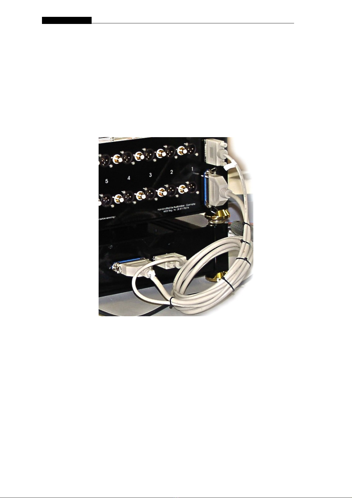
There are two cables for connectin the power supply to ether with the amplifier
( shown on the picture ). There is no possibility to mismatch the cables as they are
different.
These cables have to be connected before switchin on the amp.
Be sure, that the amplifier is disconnected from the main voltage while
connecting the cables!
The plu s are directed, there is no possibility to interchan e by plu in in.
Do not disconnect these cables when the amp is in operate mode, disconnect the cables
only when the internal power capacitors are completely dischar ed, at least 3 minutes
after shut down the amplifier by the main volta e switch OFF.
Disconnect first the main volta e cord before disconnectin these cables.

CONDUCTOR reference pre amplifier_
NSTALLAT ON AND OPERAT ON
MA N VOLTAGE
Make sure that your home volta e is the same as the printed volta e on the lable of
the rear side of the power supply.
Please notice that you never exceed the main volta e in the prescribed value shown on
the lable of the serial number on the rear side.
If you can`t provide the amplifier with the exact shown main volta e, please use
a volta e stabilizer - particulare for the US ( 117 VAC )
and Mainland China market.
PLACEMENT AND VENT LAT ON
This AudioValve CONDUCTOR amplifier is desi ned to
operate at a moderately hi h temperature. The ideal location
is on the ri id stand or floor mounted away from direct contact with any objects,
materials or deep pile carpets which may be effected by the heat or which may interrupt
the flow of air around the amplifier.
When operatin the amplifiers quite a lot of heat is enerated which should be allowed to
dissipate without restriction. Make sure that no objects are placed on the top of the
amplifier. Always ensure adequate ventilations.
MA N POWER connection is via supplied plu -in lead. The standard IEC socket connects
the mains power at the amplifier end while a local mains plu is required at the wall end.
In the event where a "local" plu needs to be fitted to the wall end of the lead, ensure
that the plu s is wired correctly by a suitable qualified or experienced person.
Ensure the amplifier is disconnected from the main voltage before attempting
any modification of the main connection.
MA N FUSE
The Mains fuse is fitted in the IEC Main / Line socket on the rear of the power supply.
The fuse must has the value 1,6A for 230 VAC and 3,15A for 117 VAC slow blow.
If the fuse keeps blowin up the amplifier must be checked by a professionel technican.
DO NEVER F T A FUSE W TH H GHER RAT NG.
NPUT TERM NALS
The 6 * RCA and XLR nputs are standard terminals for the
use of unbalanced and balanced input si nals comin from the si nal sources . The
CONDUCTOR uses for all XLR inputs female jackets and for the output male jackets.
The micro - controller handles the use of balanced or unbalanced si nals. You have to
confi ure them in a special setup - routine for each input separately.

CONDUCTOR reference pre amplifier_
OUTPUT TERM NALS
The CONDUCTOR has two pair of output terminals :
XLR and RCA
They are manuell selected by the ri ht switch next to the display.
You can choose between:
- OUTPUT 1; - OUTPUT 2; - OUTPUT 1 + 2

CONDUCTOR reference pre amplifier_
M CRO - CONTROLLER handling
the followin picture shows the most important routines that controllin your amplifier.
By manuell you can operate the amplifier via 3 small touch switches next to the display,
or with your remote control.
Screen desrcibtion
1 The left picture shows the "sleep mode" of the amp.
The amp is already turned ON by the main switch.
To et the amp in OPERATE MODE, you either use the
pin ON /OFF on the remote or press the little ON/OFF
switch underneith the display to the left side.
To et the amp in STAND BY MODE ( just the tubes are
heatin , no plate volta e) please use the STAND BY pin
on the remote or press the little switch to the ri ht
position.
2
This picture shows the OPERATE MODE, after the amp
has left the SLEEPING MODE, but just for 1 minute.
Durin this MUTE MODE the tubes are warmin up,
shown by the vertical bar raph.
It chan es from black via red to yellow, after have
reached 75% of the scale the plate volta e will be
supplied.
After 100 % are reached, the MUTE MODE is finished,
the display is chan in into picture 3.
3 This is the re ular display while operatin the amp
either by remote or with the 3 little switched around
the display.
4 This picture shows the STND BY MODE
CONDUCTOR reference pre amplifier_
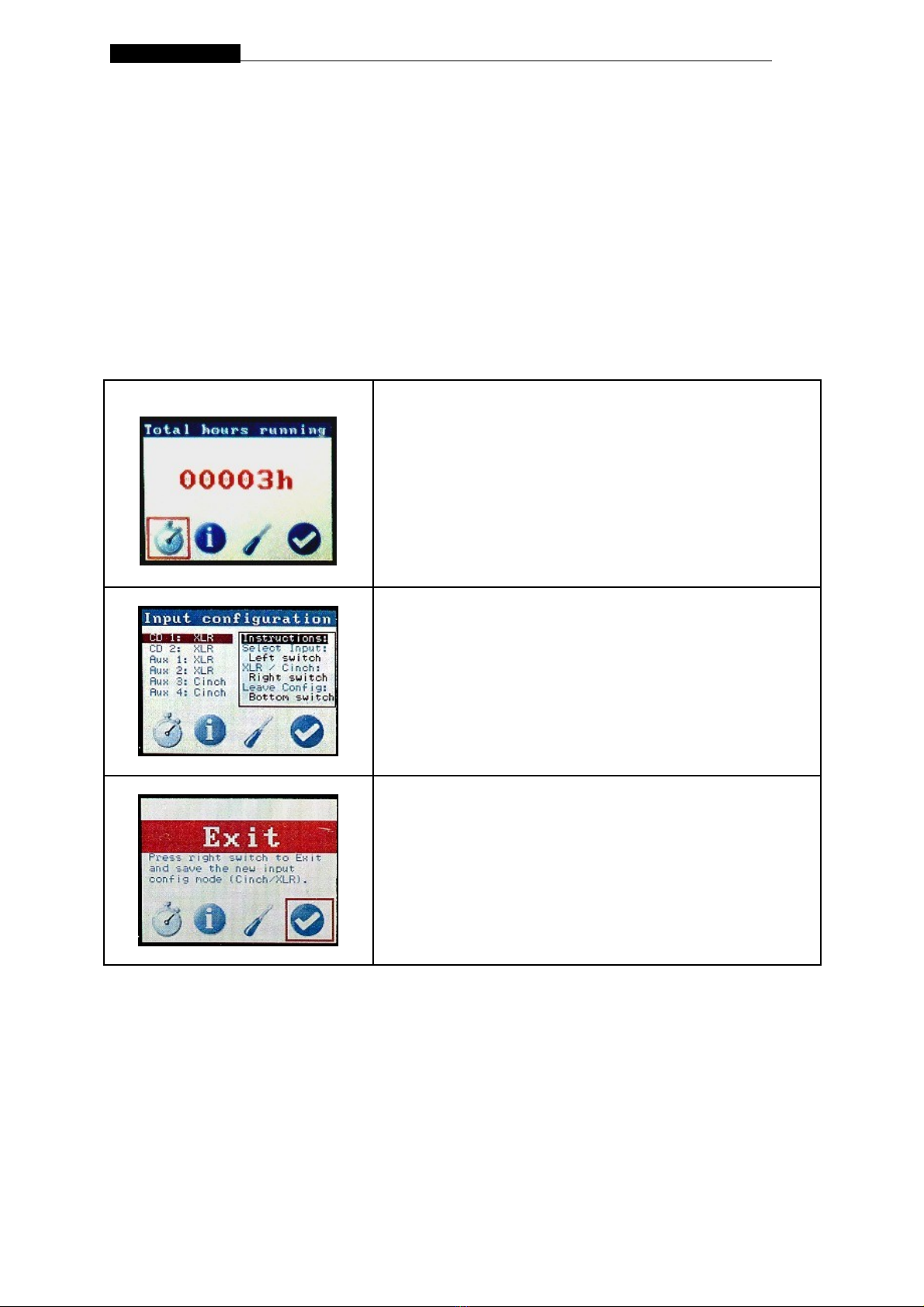
nput terminal setup menu (configuration)
All inputs are confi urated as XLR or RCA inputs for the use of
balanced or sin le ended si nal phases.
To set up your chosen inpust please TURN OFF the power supply by the main switch.
Then you press the both little switches ( left and ri ht from the display ) in an upper
position. The same time you switch on the power supply with the main switch.
Screen desrcibtion
1 CLOCK SYMBOL Fi .1 shows 4 buttons in the lower screen which offer
you different options, he actual chosen by a square red
flashin cursor. Now it shows the actual runnin hours
of your amp .
2 TOOL SYMBOL Push the left switch up or down to select the input,
then use the ri ht switch to too le between XLR or
Cinch mode.
Push the bottom switch to the ri ht side to make fix
and leave your input settlin s [ ri ht button ].
3 EXIT SYMBOL Push the ri ht switch to save the new input
confi uration and leave the setup menue.
The information symbol is just for the manifactures
interests.
Table of contents
Other Audio Valve Amplifier manuals

Audio Valve
Audio Valve RKV Mk II User manual

Audio Valve
Audio Valve RKV-MARK 3 User manual

Audio Valve
Audio Valve RKV - Mark II User manual

Audio Valve
Audio Valve CORDA EARTUBE-1 User manual

Audio Valve
Audio Valve ASSISTENT 100 Mark 2 User manual

Audio Valve
Audio Valve Assistent 50 User manual

Audio Valve
Audio Valve BALDUR 70 User manual

Audio Valve
Audio Valve LUMINARE 2015 User manual

Audio Valve
Audio Valve Eklipse User manual

Audio Valve
Audio Valve Avalon User manual


