Audio Valve SUNILDA User manual

SUNILDA
Instruction Manual
model – 2013
ultra highend RIAA MC and MM phono
amp
We congratulate you with the purchase of this superb AUDIOVALVE - HiFi co ponent.
This handcrafted product has been anufactured with only your ost de anding
require ents in ind. It was ade to allow you any years of usical joy.
AUDIOVALVE guarantees that this a plifier has been produced under the strictest of guidelines and
with respect for procedures acquired through decades of tube a plifier design. Your SUNILDA Pre-
a plifier has been thoroughly tried and tested in all detail.
I personally guarantee the quality of this product
Hel ut Becker, Design & Production

SUNILDA ultra highend phono tube amplifier____________________________
Table of contents
- Introduction and general information
- Manufacturers information
- Safety precautions
- Intended use / Application / Factory assembly & getting started
- Operating instructions & technical features
- Set - up and installation
- arranty
I n t
r o du c
t i
o n
Dear client, we congratulate you on your purchase of this superb AUDIOVALVE HiFi co ponent.
To safeguard maximum functionality and to avoid operating problems, it is important
that you carefully study this owners manual and that you follow all instructions therein
precisely!
G e
n e
r a l
i
n f o r m
a t
i
o n
I portant instructions, regarding safety, securety and operational reliability while using the
SUNILDA Pre-A plifier are highlighted throughout this anual.
F a
c t
o ry a
ddr e
ss :
AUDIOVALVE, H. Becker,
U bachsweg 70
D-34 123 KASSEL
GERMANY,
Tel.: 0049 - (0) 561 7013360
Fax: 0049 - (0) 561 6029293
E ail: i
n f o @ a
ud i
o v al
v e .
i
n f o
website: w
w w
. a
ud i
o v al
v e . info

SUNILDA ultra highend phono tube amplifier____________________________
S
a
f e
t
y p
r e
c a
u t i
o ns
I portant: Study the owners anual before asse bly and operation of the a plifier
Anyone, unable to co prehend the instructions stated in the owners anual should not operate the
device.
Children and inors are not to use the device and should be kept at a safe distance fro the
device while it is running.
The user is responsible for operating the device in an appropriate fashion and it takes full
responsibility towards third parties. Before the a plifier can be used the first ti e, suitability of taken
precautions regarding electrical safety ust be approved through professional assess ent.
Check that the ains voltage printed on the rear panel of the a plifier corresponds with the line
voltage in the territory where you intend to use the a plifier.
Always check powercords and plugs for da age before use.
Disconnect the powercord before work is being done on the a plifier.
In the unlikely case of a failure of the device repairs ay be perfor ed by
AUDIOVALVE authorized technicians only. Use
ORIGINAL spare parts only!
Please take note of the fact that we waive product liability for da ages caused bij our devices,
parts and co ponents as a result of:
a) Unprofessional and / or faulty and / or correct repairs that have been perfor ed in other
than the by AUDIOVALVE approved repair facilities,
b) Usage of other than ORIGINAL and approved spare parts.
The SUNILDA Pre-A plifier is subject to and co plies with Ger an security class 1
for devices with etal housing. The device is grounded, and ay not
–
by anipulation or otherwise -
be ungrounded for any reason! To prevent hu as a result of interconnecting your devices with the
SUNILDA Pre-A plifier, the internal electrical circuitry has been designed to have no grounded
ass!!
SUNILDA ultra highend phono tube amplifier____________________________

SUNILDA ultra highend phono tube amplifier____________________________
Product
Description
Sunilda is a three stage phono-prea plifier, based on 6922 (ECC88) and 12AX7 (ECC83) fra e
grid tubes, suitable for MM- and MC-cartridges. Independently for the two phono inputs, i pedance
and capacitive load can be set separately and 'on-the -fly' while listening. Thus the user can easily
configure the unit to atch the features of the cartridge by selecting the opti al input resistance and
capacitance for each input separately! Sunilda co es in an laser cuted 3 thick steel, chassis in
black or silver finish and has a case si ilar to the Eklipse line a plifier.

SUNILDA ultra highend phono tube amplifier____________________________
Switches are found for: MM/MC ode for each input; input 1 or 2; selectors are used to select
different R and C loads. Two selector knobs for each input capacitive and resistor load
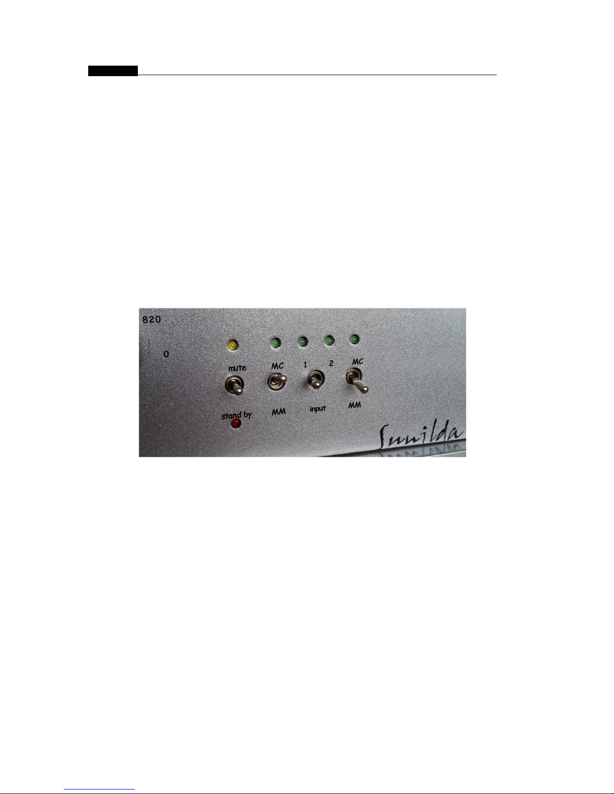
Frontpanel
f r o m
S U N I LD A
In MM ode the gain will be 20 dB lower than MC and at a fixed input- i pedance of
47K.
In MC ode the prea p will have higher gain and switchable input resistors and condensers. The
RIAA de-e phasis is passive and split between the first and second stage. Dividing the RIAA
network over two a plification stages lowers the insertion losses of the passive network
dra atically. Further ore, the design holds a total absence of feedback, thus increasing the overall
dyna ics.
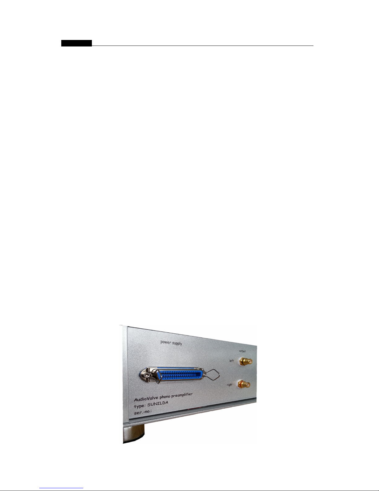
R e a
r s i
d e
p a
nel
f r o m
S U N I LD A
The power supplies are solid state regulated. This is the best way to obtain a low
noise and supply line with a very low i pedance that will increase the perfor ance in the
lower frequency range. The power transfor er is housed in a separate alu inu case. The
pic show you the real side panel with connector for the power supply ( blue left one ) and the
turntable earth grounding ter inals ( black posts ), 2 RCA cinch output jackets and 2*2 input
RCA jackets.

SUNILDA ultra highend phono tube amplifier____________________________
separate power case supply case with the MAIN switch, MAIN plug with integrated fuse holder and
the CENTRONICS ulti wire connector for the a p.
I n t
e
nd e
d u s e
/ A
p p
l i
c at
i
o n
AUDIOVALVE Hi-Fi A plifiers are intended for use under the following circu stances only:
- To play and transfer usic of any ake and fashion when this occurs in private dwellings
or studios.
- All devices ust be operated under oderate cli atological circu stances, co parable to
those underwhich hu an beings usually live. When the surrounding te perature is too high,
the device will heat up beyond its opti al para eters. This can da age the a plifier.
Proper ventilation will be needed, and the a plifier should not be covered in. Allow
approxi ately 3 c of air sidewise and approxi ately 4 c above the a plifier to cool
the a plifier.
- Unusually high hu idity of the air increases the risk of shortcircuits in the device
because
of the increased conductivity. This reduces the internal insulation values dra atically
and will eventually result in a alfunction of the a plifier. This increased conductivity
also ight endanger the user of the device. In general ter s the a plifier should not be
used for other than its intended purpose.

SUNILDA ultra highend phono tube amplifier____________________________
Factory assembly & getting started
Once the a plifier has arrived at its desired destination, ake sure the a plifier has a ple ti e to
adjust to the cli ate at its new location. It is likely that the changes in te perature and hu idity
between the last location and the new one, has caused condensation to build up so ewhere in the
a plifier.
This can da age the device. Please allow the a plifier at least two hours to accli atise.
The a plifier co es fully asse bled, ready to go. The powercord should not be used as yet, please
connect all other input and output connectors first (cinchcables, speakercables, etc).
The device MUST be switched off while connecting it to other co ponents, it ight be da aged if this
is done with the a plifier under power. The person operating the a plifier ight be hurt as well in this
case, since powerspikes, operating currents and voltage charges ay occur!
Check whether the ON/OFF switch is in the OFF position. If so, you can now plug in the
powercord.
Use high quality cables only! Usage of DIY cables, low spec cables or cables intended
for other use voids all warranty and cancels any product liability. Make sure all plugs are connected
tightly to the a plifier. When in doubt, replace the cable.
Always use the device in a
’
co plete configuration
’
, da ages ay occur when devices are not
connected to the a plifier when it is being run.
Never lift the device by its glass cover, not even when there are gripps attached to the cover. The
gripps and the cover are there for orna ental purposes only. They ake the a plifier look nice.
The a plifier should be positioned at a level surface, in ti e the construction of the glass housing ay
fail as a result of tensile forces.
Please disconnect and ove the a plifier when you replace tubes. Replace the at a place where
you can work easily. You ight da age the
’
otherboard
’
if you replace the tube in an awkward
position. After that please check all connectors. If all connectors are unda aged, ake sure the
switch is in the OFF position, reconnect the powercord and swith the a plifier on. You can ake sure
the a plifier is properly connected by checking the tubes. Only the inside of the tube should glow. If
the steel coverjacket glows as well, the device is faulty and ust be serviced i ediately.
As a rule of thu b the device should work now. Don
’
t push the volu e up to its axi u just yet,
allow the device to burn in s oothly and avoid powerspikes.
The SUNILDA Pre-A plifier needs at least a 1.6 A pere slow blow circuit breaker in the fuse holder
for 230 VAC ain voltage and 3,15 a pere slow blow by 115 VAC. Make sure your wall socket is equiped
in such a fashion.

SUNILDA ultra highend phono tube amplifier____________________________
Controls and operation on the front and rear panel
The frontside of the SUNILDA has a nu ber of controls, whose function should be elaborated
upon.
When switched ON, the a plifier is always in MUTE during the first inute - nealy one inute.
The a p is also in MUITE - function for a wile, when you handle one of its 4 little rocker
switches on the freont panel, you see the yellow LED shinning. This prevents power spikes
that ay be caused by the voltage spikes what will be produced, when you handle the little
rocker switches to reach the outputs. When the safe MUTE period is over the a plifier is ready
for use and spend the signal to the OURPUT ter inals.
Never change a fuse when the a plifier is connected to the ains or when you are unsure about
the proper functioning of the device. Never replace a blown fuse with a other values than printed
on the unit!
Whenever you perfor any service or odification to the SUNILDA Pre-A plifier, ake sure the
device has been disconnected fro the ains and leave the work to a professional only!
The design of the circuit board allows you a view upon the ost i portant ele ent that ight be
subject to service or odification.
When you decide to replace pin-co patible tubes, always switch the SUNILDA a plifier o OFF
before doing so. And ake sure all pins actually enter the sleeve of the receptor. Pins have a
tendency to wander outside their assigned real s...
The SUNILDA Concept
The SUNILDA boasts a huge a ount of innovative solutions that are hard to find in tube - a plifiers
in this price range. To balance currents in the tubes and to ake sure they operate at peak efficiency
within their tolerances, se iconductors are used. The SUNILDA has been designed to be a real
double ono a plifier, which eans both channels have their own power supply. A design
characteristic that is no standard option with even uch ore costly devices. When you switch the
volu e off, the SUNILDA is SILENT. Please note both the ini al background noise and the equaly
low input noise level the SUNILDA Pre - A plifier scored in tests.
That is no ean feat. Like all AUDIOVALVE a plifiers, the SUNILDA has been designed to be a
ti eless piece, a high closs powder coated 3 thick laser cut steel with gilded connectors. That
concludes the basic technical description of the a plifier, continue reading for the really i portant
stuff.
IIMPORTANT: In the 4th quarterly issue 2005 of the HI-FI agazine
“
xxxxx
“
the
SUNILDA have been tested and reviewed exhaustingly. These tests will probably
answer any questions regarding usical perfor ance and technical specs you ight have.

SUNILDA ultra highend phono tube amplifier____________________________
Technical Specifications:
MM ode gain: dB - 1Khz
MC ode gain: dB - 1Khz
MM / MC ode input i pedance: resistors: 1> 47R, 2> 100R, 3> 220R, 4-> 470R, 5> 1K, 6> 47 K
capacitors: 1> 0p, 2> 100p, 3> 220p, 4> 470p, 5> 1n, 6> 0p
Frequency Response: 20Hz to 65 KHz +/- 3 dB
Subsonic filter roll-off: 20 Hz
Max output a plitude: 14V pk
Max input a plitude: 200 mV
RIAA accuracy: +/- 0,25dB
Distortion: 0,24 % (1Khz - 10Vpk out)
Noise: 76 dB below signal (MC mode)
Circuit type: 3 stages single ended, buffered ouputs
RIAA network passive - split between 1st and 2nd stage
Resistors: 1 % metal film
Capacitors: MKP - styroflex - fast electrolytic
Tubes: 2 x 6922 input, 2 x 12ax7 output
ore ode functions: Stand - by and mute
Power supplies: Solid state regulated
transfor er: outside in a separate case
require ents: 115/230 - 245 Ac - 50/60Hz
consu ption: Watts: 60 VA
Di ensions: c , W x H x D : 42 * 32 * 14 ( same as Eklipse )
Weight: Kg: 20 kg
SUNILDA ultra highend phono tube amplifier____________________________
Set-up and installation of the Phono Amplifier SUNILDA
After having unpacked your phono equip ent set the phono pre- a plifier up at its chosen
place. The power supply should be positioned at a distance fro the pre-a plifier by at
least the length of the connecting cable.
Equally, other large electrical consu ers should not be positioned near SUNILDA and the
record player. The power supply can be best placed on the floor, however ake sure the
power switch on the front of the power supply is visible and within reach.
Only when anipulating this ain switch on the power supply SUNILDA is either ade
alive or, after having switched off, is co pletely dead
–
identification by eans of a red
LED at the right front of the power supply.
The LED shines, if the pre-a plifier is switched OFF at the switch on the front of the
a plifier, with the power supply, however re aining alive. The red LED signals that the
power supply is still alive.
In case the a plifier will not be used for a longer period of ti e, as f.Ex. in holiday ti es,
ake sure the a plifiers power supply case as well is cut OFF !!!!
After having set-up both appliances at first connect power supply and a plifier with the
included CENTRONICS cable and secure the cable against falling out at both ends.
Subsequently connect the power supply to ains voltage by eans of the power cord.
Ensure that the power supply is switched OFF with no LED shining at the appliance.
Now start to install the signal lines between the pick
—
up and SUNILDA. Fix the earth
conductor of the record player to the earth ter inal assigned to each input at the back of
the pre- a plifier next to the cinch inputs.
Cable the output of the SUNILDA phono pre-a plifier to your EKLIPSE pre-a plifier using
the appropriate cinch cables.
The pre-a plifier is still cut OFF. When putting the power supply into operation, the red LED
at the right front of the a plifier below the ON
–
OFF switch begins to shine.
Before you also connect the pre-a plifier, check the settings for the pick-up at the appliance .

SUNILDA ultra highend phono tube amplifier____________________________
If connecting only one syste , please use the input 1 according to the arking at the back of
the appliance. Make sure the cinch cables as well as the adjacent earth conductor are well
fitted.
At the right of the front screen you will find a row of flip switches ( little rocker switches ).
Only the switch in the iddle
–
to be actuated at level
–
indicates the input to be used by
yourself. Flip this switch to the left, if you have configured to input 1 at the back. Flip it to the
right, if you have also configured to input 2 and intend to use both inputs.
There is an additional switch each at the right and at the left of the level flip switch
–
to be
actuated vertically
–
assigning the connected pick-up by odel to the respective input. The
flip switch is flipped upwards, if a MC syste is connected to the respective input and is
flipped downwards when connecting a MM syste .
The very left switch of all 4 flip switches can M U T E the output signal, if being flipped
upwards (yellow LED) or can change into STAND - BY ode (red LED) with the switch pointing
downwards.
In this case SUNILDA is heated up without anode supply voltage. With the switch in neutral
position none of these two functions are active. This switch position is neutral and usually the
prefered position.
Relevant information:
Whenever one of these 4 flip switches is actuated, the outputs of the phone pre-a plifier are
uted
–
for a period of 15 secs.
–
to suppress the internal voltage variations at the output. This
is for safety control only. When you worried about your speakers, please adjust the pre a plifers
volu e potentio eter downwards, so that no signal spikes can be reach your power a plifier and
speakers.
I MP
E
D A
NC E
By eans of the four rotary knobs at the left side of the front screen the i pedances for the
pick-up's are selected for both outputs independantly fro each other.
Looked at fro the iddle the knobs are in a irror-inverted position, i.e. the two
iddle rotary knobs select the load resistance for the pick-ups: the iddle left knob for
input 1 and the iddle right knob for input 2. By eans of the outer rotary knobs the
appropriate leading load for the individual input is selected. You ay change these settings at
the a plifier, if required.
SUNILDA ultra highend phono tube amplifier____________________________
The two iddle rotary knobs select low i pedances for MC syste s in the first five switch
positions starting fro the left. The last position at the very right of these switches has a
47kOh load and is intended for use with MM syste s.
So for MC syste s chose the i pedances 47 R up to 1 k in the first five switch positions and select the
i pedance in the sixth switch position (MM
–
47k), if a MM syste has been connected to this
input.
According to your requests all switch positions ay be co bined in any order thus allowing the
si ulation of a large nu ber of different loads for your pick-ups.
Note:
Always turn down the volu e at the pre-a plifier to safeguard your speakers when changing the
following settings at SUNILDA:
1) When switching over fro one input to another input.
2) When switching fro MM to MC, because the a plification increases by 20dB.
A view of the co pact and absolute wireless electronic - riaa odul fro SUNILDA. There is no hu , bee
or any noise - only usic. The design on a double side pc board is constructed in double ono
technology, use best and selected co ponents and guarantee high stable and highend vinyl re -
productions.

SUNILDA ultra highend phono tube amplifier____________________________
A
R
R A N
T Y
AUDIOVALVE warrants its co ponents for a three-year period on all electronics and a 90-day
period on the tubes fro the purchase date.
In the event of a failure of your a plifier, AUDIOVALVE will repair or readjust this unit or, should
the occasion arise, will replace it provided that all conditions stipulated in this warranty are et.
In order to initiate service of any kind it is necessary to obtain distributor or dealer authorization prior
to shipping the unit for service.
Any of the following conditions shall void the warranty:
Operation not in accordance with this anual.
Abuse , accidental da age or unauthorized odifications , as deter ined by AUDIOVALVE
or its agents exclusively.
Re oval, defacing or falsifying of the serial nu bers.
Shipping without the original co plete factory crates.
A
RR A N
T Y R E GI
ST R A
T I
O N
Please fill out and return this warranty form to the distributor within 15 days of the purchase
date, or fill out our online warranty registration form at: w w w. a
u
d o v a
lv e
. i
n
f o
MODEL :
SERIAL NUMBER :
PURCHASE DATE :
AUTHORIZED AUDIO - VALVE DEALER:
PURCHASER`S NAME :
STREET ADDRESS :
CITY :
ZIP / POSTAL CODE :

SUNILDA ultra highend phono tube amplifier____________________________
CE – Confirmit
Declaration Of Conformity
Manufacturer: AudioValve,
Germany, 34123 KASSEL, Umbachsweg 70,
Product Name: SUNILDA
Product Type: Audio Amplifier
Complies with Standards:
LVD: 92/31/EEC, 93/68/EEC, & 73/23/EWG
Safety: EN60065
EMC: EN55013, EN55020, EN55022, EN55103, EN61000-3-2,
& EN61000-3-3
The official Declaration of Conformity for this product is kept on file at:
AudioValve, 34123 Kassel,Umbachsweg 70, Tel. 05617013360
This manual suits for next models
1
Table of contents
Other Audio Valve Amplifier manuals

Audio Valve
Audio Valve Conductor User manual

Audio Valve
Audio Valve ASSISTENT 30 User manual

Audio Valve
Audio Valve RKV - Mark II User manual

Audio Valve
Audio Valve CORDA EARTUBE-1 User manual

Audio Valve
Audio Valve ASSISTENT 100 Mark 2 User manual

Audio Valve
Audio Valve EARTUBE- MARK II User manual

Audio Valve
Audio Valve RKV-MARK 3 User manual

Audio Valve
Audio Valve BALDUR 70 User manual

Audio Valve
Audio Valve LUMINARE 2015 User manual

Audio Valve
Audio Valve Assistent 50 User manual


