AER HEAD ONE User manual

1. Introduction
Welcome at AER. We are very pleased that you have chosen to
buy a Head One.
You have chosen a powerful, professional-standard amplifier
that has been specifically designed for the amplification of elec-
tric basses.
The Head One’s impressive capabilities are especially noticable
with an electric bass, an instrument which has an enormous
bandwidth and variation in tonality. We believe we have achie-
ved a successful compromise. Everything else is down to you -
we believe you will have a lot of fun with Head One.
Head
one
Manual
Summary of contents:
1. Introduction
2. Precautions
3. Conception
4. Control elements
5. Technical data
6. Disposal Regulations

Head one -2-
•Do not install your Head Oneclose to equipment with strong
electromagnetic fields such as large power transformers, cir-
culating machines or neon lighting. Do not lay the signal ca-
bles parallel to heavy-duty power lines.
•Only connect your Head On when it is switched off.
•Remove the power cables before cleaning your Head One. Use
a damp cloth to clean with, do not use cleaning chemicals and
be sure that no liquid gets into the electronicsZiehen.
•The inside of the Head One does not contain parts to be ser-
viced by the user. Leave servicing, adjustment and repair to
qualified service personnel. Unqualified intervention will re-
sult in the invalidation of 2-year Guarantee.
•Please look after these operating instructions!
2. Precautions
•Read the operating instruments and be sure that you have
understood them.
•Follow all the warnings, instructions and supplementary texts
that are written on the Head One.
•Always use an earthed power supply with the correct AC vol-
tage. Should you be unsure about the earthing of the power
supply, have it checked by a qualified electrician.
•Do not install or use your Head One close to water, or if you
are yourself wet.
•Use your Head One where it is protected and where no-one
can tread on the cables or fall and damage them.
To avoid injury through Fire and Electric Shock when using the Head One, always be sure to adhere to the following
safety precautions.

Head one -3-
3. Conception
The AER Head One is an integrated amplifier (Preamp plus
Power Amplifier) specifically designed to amplify electric or
semi-acoustic bass instruments.
As with all of our amplifiers, we place great value in designing
amplifiers as small as possible. The weight of an amplifier is as
important to us as the quick response, the efficiency (90% at
maximum volume) and the level of dynamic the Head One can
attain.
The extremely high efficiency and the acoustic output of the
Head One make this amplifier an integral part of the AER Series,
which is dedicated to developing modular amplification equip-
ment for electric musical instruments.
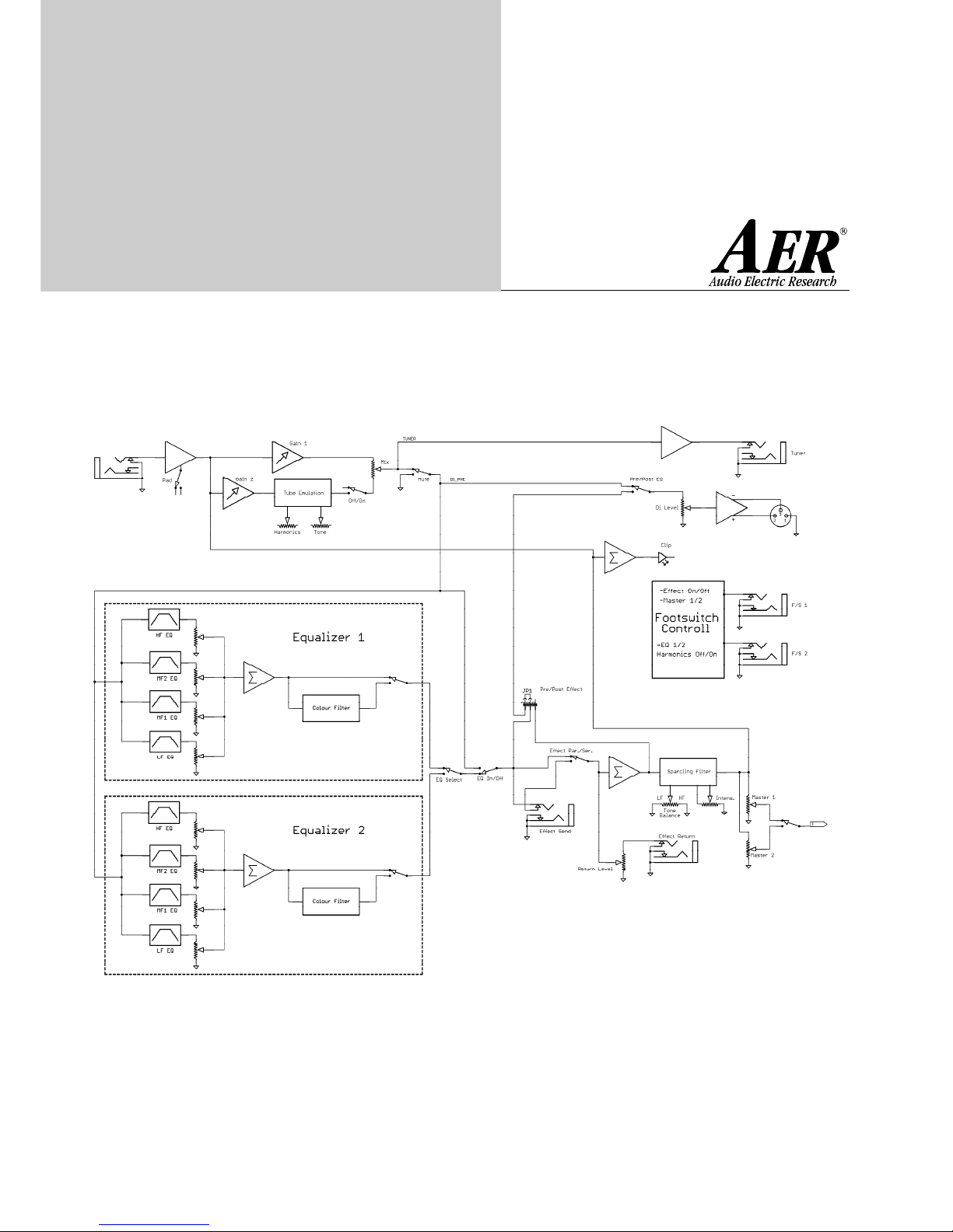
Please use the included block diagram which describes the most
important functions and characteristics.
The most important function characteristics are to be found
described on the attached block diagram.
The Head One contains one signal input and two corresponding
pre-amplifiers.
The sensitivity of all signal levels can be controlled using the Pad
ans Gain 1. Parallel to this signal path is a further Pre-Amplifier.
This is controlled the Pad and/or Gain 2 and together with a
Tube Emulation creates a distorted sound that can consequent-
ly be added to the clean sound using the Mix control.
Harmonics and Tone influence the type and frequency response
of the created distortion.
The Mute switch switches off the amplifier and all Outputs
except the Tuner Output.
The signal progresses further to two Equalizer Stepps which can
be selected by a switch, or can be bypassed by a secondary
switch. Consequently one has the opportunity to select be-
tween two seperate sound settings..
The DI Output has a seperate signal control. It's possible to
access the signal before or after the EG by using the Pre/Post EQ
switch. Following that is a Send/Return circuit (i.e. for Effects) to
enable signals to added either in parallel or in series.
The next Sound Control (Sparcling Filter) influences the whole
signal in the area of Bass and Treble, through a type of Sound
Scales and an intensity knob.
Using two selectable Master Controls (i.e. for Solo or Ensemble
level) the signal is passed on to the Line Out and an analogue
Signal Controller. This stops overloading of the power amplifier,
allowing an optimal allignment of the connected loudspeaker
from the AER Bottom Line Section.
A maximum of two footswitches can be connected allowing
remote control of the following functions:
•Gain2 or Tube Emulation on/off (can be connected to the Ma-
ster and/or EQ-switching, via a Jumper. Factory setting is with-
out connection)
•Equaliser 1 or 2 selection
•Master 1 or 2 selection
•Effect circuit on/off
The Power Amplifier is a 2 channel digital amplifier that can be
used in 3 different modi:
1. 2-Ch Mode: As a Fullrange Amplifier driving 2 full-range
loudspeaker boxes
2. 2-Way Mode: As a 2-Way active amplifier with one output
for a Bass Loudspeaker Cabinet and one for a High/Mid
Cabinet.
3. Bridge Mode: As a bridged amplifier for a higher output
level for use with a full-range cabinet (only recommeded for
use with an 8 Ohm cabinet)
The active crossover, neccessary for 2-way operation, can be
found before the power amplifier in the signal path.
The Bass and Treble signals can accessed at line level outputs,
thereby allowing connection to external amplifiers with louds-
peaker systems or active loudspeakers.
A switched power supply supplies the power amplifier with con-
stant working and the neccessary energy.
Extensive protection switching helps to protect the operating
parts against damage caused by incorrect operation or opera-
ting conditions.

Head one -4-
input Input socket
Mono/Stereo Jack
pad Switch for adjustment of input sensitivity
gain 1 Controls the proportion of input signal
(preamplification)
clip Indicator of input distortion
mute Mutes channel
drive:
gain 2 Controls the preamplification of the
‘drive’ channel
harmonics Control to alter the characteristics of the
distortion
tone Controls the treble content of the ‘
drive’channel
off/on On/off switch for the distortion
mix Controller to mix 'gain1' and 'gain2'
together
tone:
balance High/Low sound balance
intensity Controls the content of the sound balance
master:
ensemble / Master 1
solo Master 2
DI out Balanced DI output
DI level DI output contol
pre/post DI Pre or post tone control
4. Operating controls
Front panel, from left to right:
eq:
bypass
select Selects between EQ 1 and EQ 2
equalizer 1:
active LED indicates that EQ1 is in operation
colour Mid-cut high boost switch
bass Bass tone control
low mid Low mid range control
middle Mid range control
treble High range control
equalizer 2:
active LED indicates that EQ2 is in operation
colour Mid-cut high boost switch
bass Bass tone control
low mid Low mid range control
middle Mid range control
treble High range control
fs eq 1/2 Jack socket for a foot switch to switch
between equalisers
fs ensemble/solo Stereo Jack socket to switch
between Masters
(Tip = master solo, Ring = master ens.)
power Power on/off switch
gain1
pad
toneoff /on
harmonics
»mute
solo
ensembleDIDI-level
power
pre/post
clip
gain1
power
on
gain2
»eq»equalizer1
…AER_BottomLine
»tone» mix»master»drive
»
input
»He a do n e
selectcolour
bypass activecolour
active
select/harmonicseffecton /off
»equalizer2
bass treble
middle
lowmid bass treblemiddlelowmid
»eq
balanceintensity
temp
boost
amp
on
gain2
»fs
eq1/2
»fs
ensemble/solo
Upper row: Lower row:

Rear panel, from left to right
tuner Tuner output excluding tone control
or effects
line Output, including Master with tone
controls, effect, stereo return of
external effects
highpass At this output is a high-pass signal,
regardless of the operating mode of
the Head One.
lowpass At this output is a low-pass signal,
regardless of the operating mode of
the Head One.
(When the 2-way mode is used,
a high-pass signal only is available all
loudspeaker outputs)
return Return signal from external effect units
send Sends the pre-amp signal to external
effects
return level Controls the amount of return signal
from external effects
Par/ser switch Select switch for external effects,
whether insert mode is in parallel or series
mode:
full-range see illustration
2 way active see illustration
bridge mode As a bridged amplifier for a higher output
level for use with a full-range cabinet
(only recommeded for use with an
8 Ohm cabinet)
out 3 Loudspeaker output (Rmin = 8 Ohm)
delivers full-range signal in bridge mode
out 2 Loudspeaker output (Rmin = 4 Ohm)
delivers full-range signal in Bridge Modus
or high-mid signal in 2-way-mode
out 1 Loudspeaker output (Rmin = 4 Ohm)
delivers full-range signal in Bridge Modus
or bass signal in 2-way-mode
powercon Connection to mains
fuse Fuse 6,3 Ampere
gnd Protective earth conductor
Head one
tunerhighpass return
linelowpass send return
level
par
ser
fullrange
2wayactive
2channel
bridge
out3out2out1powercon
fuse
gnd
mode
Preamplifier
Amp 1
Amp 2
CAB one
CAB one
Preamplifier
CAB one
CAB two
Amp 1
Lowpass
Amp 2
2-Way-Active
out 2
out 1 out 1
out 2
2 Channel Full-Range mode
Highpass
-5-

out 1
out 2
out 2out 1
head one
Head one -6-
out 1
Full-range mode
2-way-active
Applications:
CAB one
head one
out 2out 1
CAB one
CAB one
head one
out 1
CAB two
head one CAB two
CAB two
head one CAB one
CAB two
2-way-active plus
head one
out 2
CAB oneCAB one
lowpass
2-channel amplifier
CAB two
CAB one
switch mode:
2-way
switch mode:
full-range
switch mode:
full-range
switch mode:
full-range
out 1

Head one -7-
5. Technical data
Mode input
Input: 1/4" unbalanced
Senstive: -26 dbV
Pad: -15 dbV
Output: 1/4" unbalanced
Tuner: 1.3V , 100 Ohm
Line out: max. 1.4V (post master)
Eff. send: max 1.2V
Output: XLR
DI-out: einstellbar 60-240 mV, balanced
Output: powercon
HF, LF, full-range signal
EQ 2:
Out 1: 250/4 Ohm (single ended)
Out 2:250/4 Ohm (single ended)
Out 3 Bridge-mode: 500/8 Ohm
Colour: -3dB / 300Hz
+7dB / 4 kHz
EQ 1:
Bass: +/- 9 dB / 45 Hz
Low Mid: +/- 9 dB / 240 Hz
High Mid: +/- 9 dB / 880 Hz
Treble: +/- 9 dB / 7.2 kHz
EQ 2:
Bass: +/- 9 dB / 45 Hz
Low Mid: +/- 9 dB / 420 Hz
High Mid: +/- 9 dB / 880 Hz
Treble: +/- 9 dB / 7.2 kHz
Weight: 6 kg
Dimensions: 88 x 366 x 306 mm
Head one -8-
Block diagram 1

Head one -9-
Block diagram 2
II
I

Head one -10-
The Company AER GmbH is registered at the
German Registration Office, EAR, under the WEEE
registration number DE2631529
EU, Norway, Iceland and Liechtenstein
In the European Union, Norway, Iceland and Liechtenstein,
disposal of electrical refuse together with domestic refuse
is not allowed.
All AER GmbH electrical equipment relevant to the WEEE regu-
lations, manufactured since 13.08.2005, has been supplied with
a crossed waste bin sign. This sign denotes that the equipment
may not be disposed with the domestic refuse. This is also valid
in Norway, Iceland and Liechtenstein.
Publication in this form has been required since 13.08.2005.
The European regulations of WEEE have been implemented in
the national laws of all European countries. Because of this we
are unable to offer standard disposal solutions.
The distributor or importer in a particular country is
responsible for abidance of the countries regulations, and is
must thereby be responsible for the disposal of old electrical
equipment, according to the national laws.
For other Nations
For professional disposal of old electrical equipment, please
refer to your local distributor or the relevant authority.
7. Regulations for Disposal
Regulations regarding the disposal of old electrical equipment.
It is not allowed to dispose of old electrical equipment together
with domestic refuse.
Old AER GmbH electrical equipment should not be disposed of
at public electrical refuse disposal centres.
The company AER GmbH is solely responsible for the disposal of
old AER GmbH electrical equipment, which is marked with the
sign of a refuse bin.
Before disposing of old AER GmbH electrical equipment carry-
ing a refuse bin sign, please contact us. We will take care of a
professional and self-financing disposal.
For old AER GmbH electrical equipment not carrying a waste bin
sign, the owner is responsible for a professional disposal accor-
ding to legislation.
In this case we will gladly help you and recommend a professio-
nal disposal contact.
By calling us on +49 (2361) 89 17 89, we can give you qualified
information regarding the disposal of old AER GmbH electrical
equipment.
Declaration:
The EU directive regarding the disposal of electrical equipment,
(WEEE,22/96/EC) has been implemented according to the law.
All AER GmbH electrical equipment relevant to the WEEE
regulations, manufactured since 13.08.2005, has been supplied
with a crossed waste bin sign. This sign denotes that the
equipment may not be disposed with the domestic refuse.
Publication in this form has been required since 13.08.2005.
A
www.aer-amps.com HeadOne_E_01/07
Table of contents
Other AER Amplifier manuals

AER
AER Compact Classic pro User manual

AER
AER The Acoustic People Compact 604 User manual

AER
AER Compact 60 3 User manual

AER
AER The Acoustic People Compact 604 User manual

AER
AER Compact Classic pro User manual

AER
AER Basscube User manual

AER
AER COMPACT MOBILE 2 User manual

AER
AER Compact 603 User manual

AER
AER COMPACT 60 2 User manual

AER
AER Compact Mobile2 User manual

AER
AER Cubello User manual

AER
AER Basic Performer User manual

AER
AER BINGO User manual

AER
AER Compact XL User manual

AER
AER Domino 2A User manual

AER
AER The Acoustic People pocket tools colourizer User manual

AER
AER pocket tools dual mix User manual

AER
AER COMPACT MOBILE 2 User manual

AER
AER Domino 2A User manual

AER
AER Compact XL User manual


