Audiodesign PAMX3.82 User manual
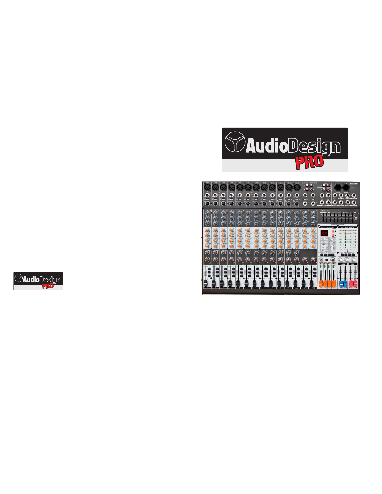
OWNER MANUAL
PROFESSIONAL MIXER
PAMX3.82 - PAMX3.122
DIFFUSORI, AMPLIFICATORI PROFESSIONALI E ACCESSORI
Audiodesign Srl
Via dell’industria, 28 - 42025 CAVRIAGO (RE)
+39 0522 941444 - Fax +39 0522 942363
www.audiodesign-pro.com

MIC IN------MAIN OUT L/R
76dB @620ohm Load, balanced
MIC IN------REC OUT
60dB @10Kohm Load
ST LINE IN------MAIN OUT L/R
26dB
MIC IN------L/R,SUB,AUX OUT
70dB @620ohm Load, unbalanced
MIC IN------EFF OUT
74dB @620ohm Load
AUX RET------MAIN OUT L/R
28dB
Max gain Signal route Conditions
@620ohm Load, balanced
@620ohm Load, balanced
2 TK IN ------MAIN OUT L/R
28dB @620ohm Load, balanced
1
4
1
1
150ohm
75ohm
10Kohm
+10dB
-10dB
+4dB
75ohm +4dB
1100ohm 3mW @36ohm
175ohm +4dB
275ohm +4dB
Outputs Number Outputs modes
AUX SEND
Stereo REC OUT
HEADPHONE
Balanced
Unbalanced
Stereo out
Connector
2 RCA
3-poles TRS
Stereo MAIN OUT
Unbalanced
Unbalanced
Unbalanced
Unbalanced
2 TRS
2 XLR
EFF SEND
SUB OUT
Stereo MAIN OUT
2 TRS
4 TRS
2-poles TRS
Output level
Rated
Impedance
Outputs
6/10
6/10
1
2Kohm
47Kohm
10Kohm
-60dB
-40dB
-10dB
210Kohm -10dB
210Kohm -10dB
Unbalanced
Unbalanced
Unbalanced
Balanced
Balanced
Input modes
Number Connector
2 TRS
3-poles TRS
XLR
2 RCA+2 TRS
Inputs
Microphones
Mono LINE IN
Stereo LINE IN B
Stereo AUX RET
Stereo LINE IN A
110Kohm -10dB
Unbalanced 2 RCA
Stereo PLAY IN
3-poles TRS
Input level
Rated
Input
Impedance
Channel EQ HI 12KHz MID 2.5KHz LOW 80Hz max equalizing value +/-15dB
Main Graphic EQ 63,125,250,500Hz,1,2,4,8,16KHz max equalizing value +/-12dB
Effect Processor 99 effect DSP
<0.1% @+14dB 20~20000Hz 620ohm loadTotal harmonic distortion
+1/-2dB @+4dB 20~20000Hz 620ohm load
Frequency response
+20dB/+26dB<balanced> @0.5%THD 1KHz 620ohm load Max out level
-124dB @ 150ohm , at max gainMicrophone preamp E.I.N
PAGE 15
Introduction/Features … …
Precautions……………………………………………… 3
Mono channel section ………………………… 4
The stereo channel(A) ………………………… 5
The stereo channel(B) ………………………… 9
Master control section……………………………7
Set up MEMO………… … ……… … ………… … …… 10
Effect List… … … … … … … … … … … … … … … … 11
Connection cables……………………………………12
System block diagram… … … … … … … … … … … 13
Application example… … … … … … … … … … … … 14
Specifications …………………………………………15
… … … … … … … … … … 2
PAGE 2
35VA 45VA
412x372x86 518x372x86
PAMX3.82 PAMX3.122
Power
Power consumption
Weight (Kg)
Dimensions(mm)
Type
INTRODUCTION / FEATURES
Welcome you using the this series portable mixer.
These mixers have handsome outline, perfect
functions.
It is easy to schlep or operate. It has two group
outputs and 4 AUX output and it is suitable for a wide
variety of input sources.
There is a effect processor with in the unit, it must
be a ideal equipment you need.
Please read this manual carefully to know all
functions and operations of the products well, in order
to operate the unit at the good condition.
FEATURES
6 or 10 mono input channels and 4 stereo
input channels(2 among 4 stereo input
channels are also used as microphone's
input).
2 auxiliary inputs and 4 auxiliary outputs.
With INSERT function for Mono input channel
Adopt low-noise discrete Mic pre-amplifier on
all microphone inputs, 3-band frequency
equalizer for each input channel.
Built-in +48V phantom power for condenser
microphone.
Signal and peak indicators on each input
channel.
Real two groups output, 60mm slide fader.
4 groups of 12 LED level meter to show the
main out level and the groups out Level.
4 groups of 4 LED level meter to show the 4
AUX out Level.
9-band stereo graphic EQ.
Volume control for headphone out.
Stereo record out and stereo in for tape play.
An effector outside can be linked.
CONTENTS
SPECIFICATIONS
NOTICEINSTRUCTION
1.Check the AC voltage before connecting the
AC plug. Proper grounding is a necessary
practice to prevent electric shock hazards to
the operator, the microphone user, and the
musicians who are wired to this unit.
2.Before switching on the main power, keep
all the output fader all the way down to
prevent damage or excessive noise caused by
bad level adjustment, wrong wiring, defective
cables or bad connection.
3.Always turn on the mixer before the power
amplifier; turn off the mixer after the amplifier.
4.Always turn off the unit before connecting
and disconnecting the unit from the power
source.
5.Never use solvents to clean the unit. Clean
with a soft, dry cloth.
AC110V;120V;220V; 230V Refer to the label on the back panel
PROFESSIONAL MIXER
Serie PAMX3
PROFESSIONAL MIXER
Serie PAMX3
PAGE 3PAGE 14
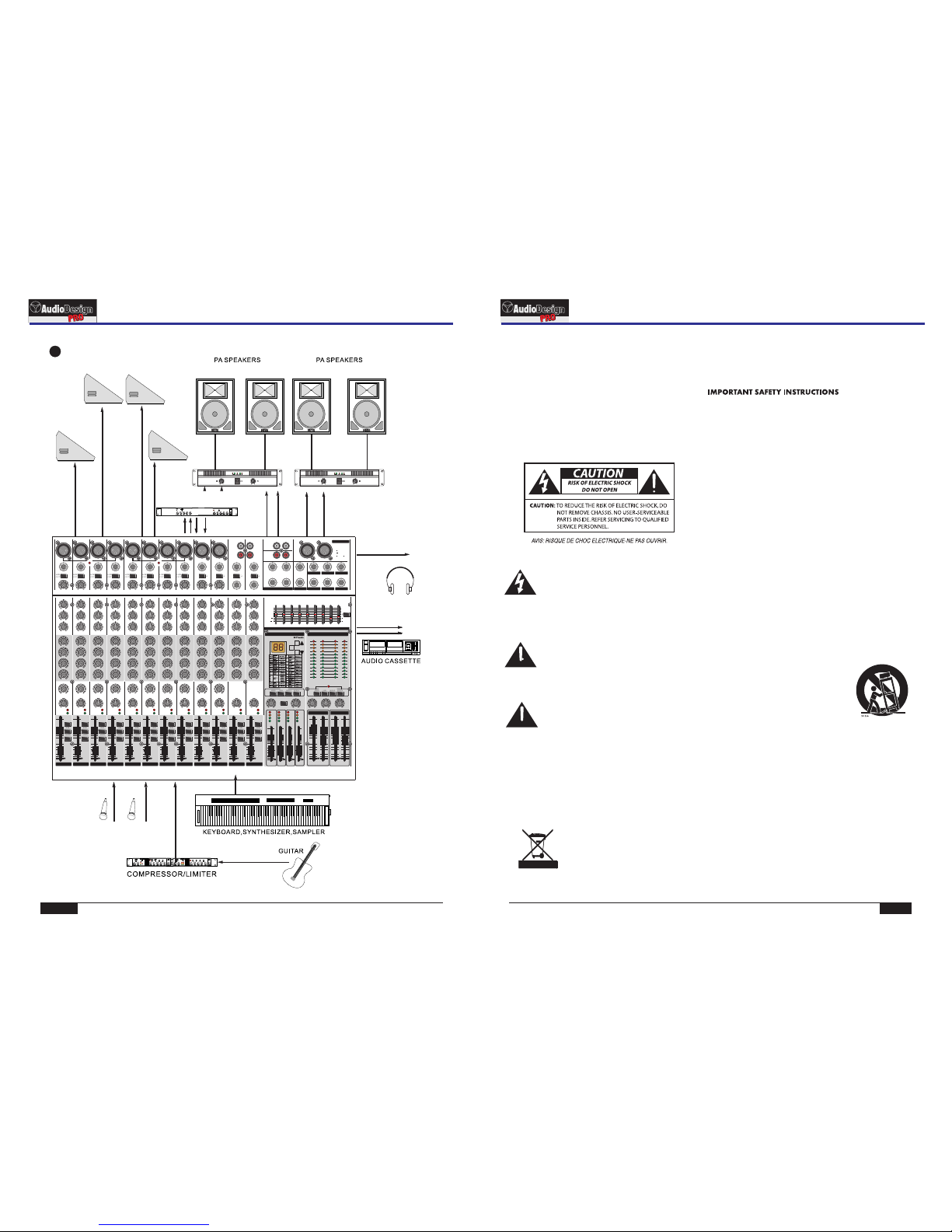
CONNECTION EXAMPLE
1. Read all safety and operating instructions before using
this product.
2. All safety and operating instructions should be kept for
future reference.
3. Read and understand all warnings listed on the
operating instructions.
4. Follow all operating instructions to operate this product.
5. This product should not be used near water, i.e. a bathtub,
sink, swimming pool, wet basement, etc.
6. Use only a dry cloth to clean this product.
7. Do not block any ventilation openings. The product should not
be placed fat against a wall or placed in a built-in enclosure
that will impede the fow of cooling air.
8. Do not install this product near any heat sources, such
as radiators, heat registers, stoves or any other apparatus
(including heat–producing amplifers) that produces heat.
9. Do not defeat the safety purpose of the polarized or
grounding-type plug. A polarized plug has two blades with
one wider than the other. A grounding-type plug has two
blades and a third grounding prong. The wide blade or the
third prong are provided for your safety. If the provided plug
does not ft into your outlet, consult an electrician for
replacement of the obsolete outlet.
10. Protect the power cord being walked on or pinched,
particularly at plugs, convenience receptacles and the point
where they exit from the apparatus. Do not break the ground
pin of the power supply cord.
11. Only use attachments specifed by the manufacturer.
12. Use only with the cart, stand, tripod, bracket,
or table specifed by the manufacturer or
sold with the apparatus. When a cart is
used, use caution when moving cart/
apparatus combination to avoid injury
from tip-over.
13. Unplug this apparatus during lightning storms or when
unused for long periods of time.
14. Care should be taken so that objects do not fall and liquids
are not spilled into the unit through the ventilation ports or
any other openings.
15. Refer all servicing to a qualifed service professional. Servic
ing is required when the apparatus does not operate normally
or has been damaged in any way, including damage to the
power cord or plug, damage due to liquids spilled or objects
dropped inside the unit, dropping the unit, or anything else
that interrupts normal use of the unit.
16. WARNING: To reduce the risk of fre or electric shock, do not
expose this apparatus to rain or moisture.
17. When a mains plug is used as the disconnect device, the
disconnect device shall remain readily operable.
Important Safety Instructions
Exposure to extremely high noise levels may cause
permanent hearing loss. Individuals vary considerably
to noise-induced hearing loss but most will lose some
hearing if exposed to intense noise for a suffcient
period of time.
DANGER
THIS SYMBOL IS INTENDED TO ALERT THE USER TO THE PRESENCE
OF NON-INSULATED “DANGEROUS VOLTAGE” WITHIN THE
PRODUCT’S ENCLOSURE THAT MAY BE OF SUFFICIENT MAGNITUDE
TO CONSTITUTE A RISK OF ELECTRIC SHOCK TO PERSONS
THIS SYMBOL IS INTENDED TO ALERT THE USER TO THE PRESENCE
OF IMPORTANT OPERATING AND MAINTENANCE (SERVICING)
INSTRUCTIONS IN THE LITERATURE ACCOMPANYING THE UNIT.
APPARATUS SHALL NOT BE EXPOSED TO DRIPPING OR SPLASHING
AND THAT NO OBJECTS FILLED WITH LIQUIDS, SUCH AS VASES,
SHALL BE PLACED ON THE APPARATUS.
SAFETY INSTRUCTIONS
Connection example
PROFESSIONAL MIXER
Serie PAMX3
PROFESSIONAL MIXER
Serie PAMX3
EFFECT PROCESSOR
REC OUT L/R
LINE IN L/RLINE IN L/RMIC IN
Eff Send
AUX Ret
SUB OUT
HEAD PHONES
MIC IN
RIGHT
LEFT
POWER AMP
ST. MAIN OUT L/R
LINE LINE LINE LINE LINE LINE LINE LINE LINE LINELINE
MIC1 MIC2 MIC3 MIC4 MIC5 MIC6 MIC7 MIC8 MIC9 MIC10
GAIN GAIN GAIN GAIN GAIN GAIN GAIN GAIN GAINGAIN
LOW
CUT
LOW
CUT
LOW
CUT
LOW
CUT
LOW
CUT
LOW
CUT
LOW
CUT
LOW
CUT
-10 -10 -10 -10
dB dB dB dB
HI HI HI HI HI HI HI HI HI HI HI HI
MID MID MID MID MID MID MID MID MID MIDMID MID
LOW LOW LOW LOW LOW LOW LOW LOW LOW LOW LOW LOW
AUX1 AUX1 AUX1 AUX1 AUX1 AUX1 AUX1 AUX1 AUX1 AUX1 AUX1 AUX1
AUX2 AUX2 AUX2 AUX2 AUX2 AUX2 AUX2 AUX2 AUX2 AUX2 AUX2 AUX2
AUX3 AUX3 AUX3 AUX3 AUX3 AUX3 AUX3 AUX3 AUX3 AUX3 AUX3 AUX3
AUX4 AUX4 AUX4 AUX4 AUX4 AUX4 AUX4 AUX4 AUX4 AUX4 AUX4 AUX4
EFF EFF EFF EFF EFF EFF EFF EFF EFF EFF
PAN PAN PAN PAN PAN PAN PAN PAN BAL BAL BAL BAL
R
L
R
L
L
R
L
R
ST LINE 15/16
ST LINE 13/14
LR
REC OUT LR
BALANCED BALANCED
2TK IN
LR
AUX1
L/MONO
R
AUX SEND AUX RET
0
+6
+12
0
+6
+12
1KHz 2KHz 4KHz 8KHz 16KHz500Hz250Hz125Hz63Hz
EQ
ON
MAIN L MAIN R/PFL SUB 1 SUB 2
6
12
6
12
1 GROUND
2 HOT (+)
3 COLD ( )
SUB2 OUT PHONESSUB1 OUT
MAIN R OUT EFF SENDMAIN L OUT
PFL
MAIN SUB AUX1/2 AUX3/4
EFF TO PHONES SELECTOR
+20 +60 +20 +6 0 +20 +60 +20 +60 +20 +6 0 +20 +60 +20 +60 +20 +6 0 +20 +60 +20 +60
-15 +15 -15 +15 -15 +15 -15 +15 -15 +15 -15 +15 -15 +15 -15 +15 -15 +15 -15 +15 -15 +15 -15 +15
-15 +15 -15 +15 -15 +15 -15 +15 -15 +15 -15 +15 -15 +15 -15 +15 -15 +15 -15 +15-15 +15 -15 +15
-15 +15 -15 +15 -15 +15 -15 +15 -15 +15 -15 +15 -15 +15 -15 +15 -15 +15 -15 +15 -15 +15 -15 +15
010 010 010 010 010 010 010 01 0 010 010 010 010
010 010 010 010 010 010 010 01 0 010 010 010 010
010 010 010 010 010 010 010 01 0 010 010 010 010
010 010 010 010 010 010 010 01 0 010 010 010 010
010 010 010 010 010 010 010 01 0 010 010
LRLRLRLRLRLRLRLRLRLRLRLR
PK PK PK PK PK PK PK PK PK PK PK PK
SIG SIG SIG SIG SIG SIG SIG SIG SIG SIG SIG SIG
010 010 010 010 010
MAIN OUT
AUX2
AUX3 AUX4
MAIN SUB AUX1/2 AUX3/4
EFF SEND 2TK IN AUX RETEFF LEVEL PHONES
STEREO GRAPHIC EQUALIZER
POF ESSIO NAL MIX ER
OUTPUT LEVEL INDICATOR
+48V +48V
MICMIC
ST ST
9/10 11/12
PFL
DSP EFFECTS PROCESSOR
MUTE
PHANTO M PHANTOM
+10
+7
+4
+2
0
-2
-4
-7
-20
-10
-30
CLIP
+10
+7
+4
+2
0
-2
-4
-7
-20
-10
-30
PFL PFL PFL PFL PFL PFL PFL PFL PFL PFL PFL PFL
SUB SUB SUB SUB SUB SUB SUB SUB SUB SUB SUB SUB
MAIN MAIN MAIN MAIN MAIN MAIN MAIN MAIN MAIN MAIN MAIN MAIN
10 10 10 10 10 10 10 10 10 10 10 10
-50 -50 -50 -50 -50 -50 -50 -50 -50 -50 -50 -50
-30 -30 -30 -30 -30 -30 -30 -30 -30 -30 -30 -30
-20 -20 -20 -20 -20 -20 -20 -20 -20 -20 -20 -20
-15 -15 -15 -15 -15 -15 -15 -15 -15 -15 -15 -15
-10 -10 -10 -10 -10 -10 -10 -10 -10 -10 -10 -10
123 4 5 6 7811/12
10 10
-50
-30
-20
-15
-10
PK PK PK PK PK PK PK PK PK PK PK PK
SIG SIG SIG SIG SIG SIG SIG SIG SIG SIG SIG SIG CLIP CLIP CLIP CLIP
+6 +6 +6 +6
0 0 0 0
-20 -20 -20 -20
10 10 10 10
-50 -50 -50 -50
-30 -30 -30 -30
-20 -20 -20 -20
-15 -15 -15 -15
-10 -10 -10 -10
AUX1 AUX2 AUX3 AUX4 L
MAIN
R
SUB
12
9/10
15/16
13/ 14
0 0 0 0 0 0 0 0 0 0 0 0 0
0 0 0 0
-50
-30
-20
-15
-10
0
1
2
3
1
2
3
1
2
3
1
2
3
1
2
3
1
2
3
1
2
3
1
2
3
1
2
3
1
2
3
1
2
3
1
2
3
1
2
3
1
2
3
1
2
3
1
2
3
1
2
3
1
2
3
1
2
3
1
2
3
1
2
3
1
2
3
1
2
3
1
2
3
RIGHT
LEFT
POWER AMP
AUX 1
AUX 2
AUX 3
AUX 4
PAGE 13PAGE 4
2
3
4
5
6
7
1
LINE
MIC1
GAIN
LOW
CUT
HI
MID
LOW
AUX1
AUX2
AUX3
AUX4
EFF
PAN
PFL
SUB
MAIN
10
-50
-30
-20
-15
-10
1
+20 +6 0
-1 5 +15
-1 5 +15
-1 5 +15
010
010
010
010
010
LR
PK
SIG
0
1
2
3
1
2
3
9
12
13
11
8
14
10
SYSTEM BLOCK DIAGRAMS
System block diagrams
CONTROL PANEL
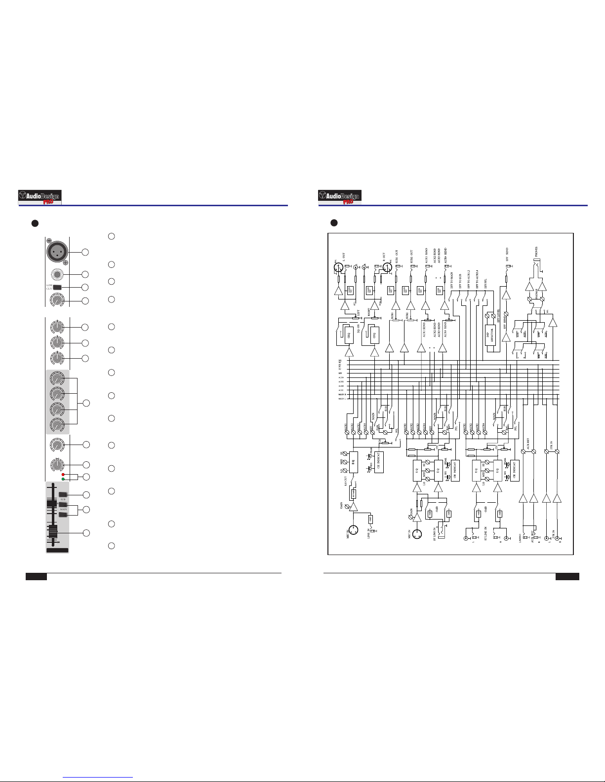
Mono channel section
LOW CUT Switch:
3
Press this switch, can dacay the input signal under 75Hz.
LINE Input:
2
This is a balanced/unbalanced jack for linking a line level source, input level range: -
40~0dB
1MIC Input
This is an XLR type connector for microphone, the input level range: -60~-20dB.
This connector can offer +48V phantom power for condenser microphone when the
phantom power switch is on.
GAIN:
4
Use this knob to adjust the level of the input signal to the optimal level. For the best
balance of S/N ratio and dynamic range, adjust this knob so that the peak indicator
12 lights occasionally.
HI :
5
This knob control the frequency equalizer at higher frequency point.
Max adjust range: 15dB @ 12KHz±
MID
:
6
This knob control the frequency equalizer at middle frequency point.
Max adjust range: ±15dB @ 2.5KHz
LOW:
7
This knob control the frequency equalizer at lower frequency point.
Max adjust range: ±15dB @ 80Hz
AUX1,AUX2,AUX3,AUX4:
8
These 4
parts are all set in front of the channel fader, so they are not dependent on the fader
knobs are used for controlling the signal level feed to AUX1~4 bus, these 4
EFF:
9
This knob is used for controlling the signal level feed to EFF bus, it has been set after
the channel fader, so it is enslaved to the fader position. Adjust these knobs when you
use effector on this channel.
10 PAN :
This konb is used for distributing the signal level of the channel feed to L/R buses.
They are equal which are feed to bus when the knob locates in the middle .
11
CHANNEL FADER:
This fader controls the output level feed to main bus from the input channel, adjusting the volume
balance between channels. Faders of channels not in use should be pulled down.
12 SIG,PEAK Indicador:
These two LED indicators detect the signal level which exists at the end of the
channel but in front of the channel fader. SIG LED flashing means the channel is in
normal, and PEAK LED will be light at 6dB before clipping to remind that the signal
level is too strong to the unit will be overload.
13 PFL :switch
This switch allows you to monitor the signal of the input channel, the signal is
sampled in front of the channel fader, so it has nothing to do with the fader position.
14 SUB,MAIN channel output control:
These two switches control if the channel signal will feed to the SUB and MAIN bus
or not separately. The switch should be turned off for unused channels.
PROFESSIONAL MIXER
Serie PAMX3
PROFESSIONAL MIXER
Serie PAMX3
PAGE 5
CONTROL PANEL
PAGE 12
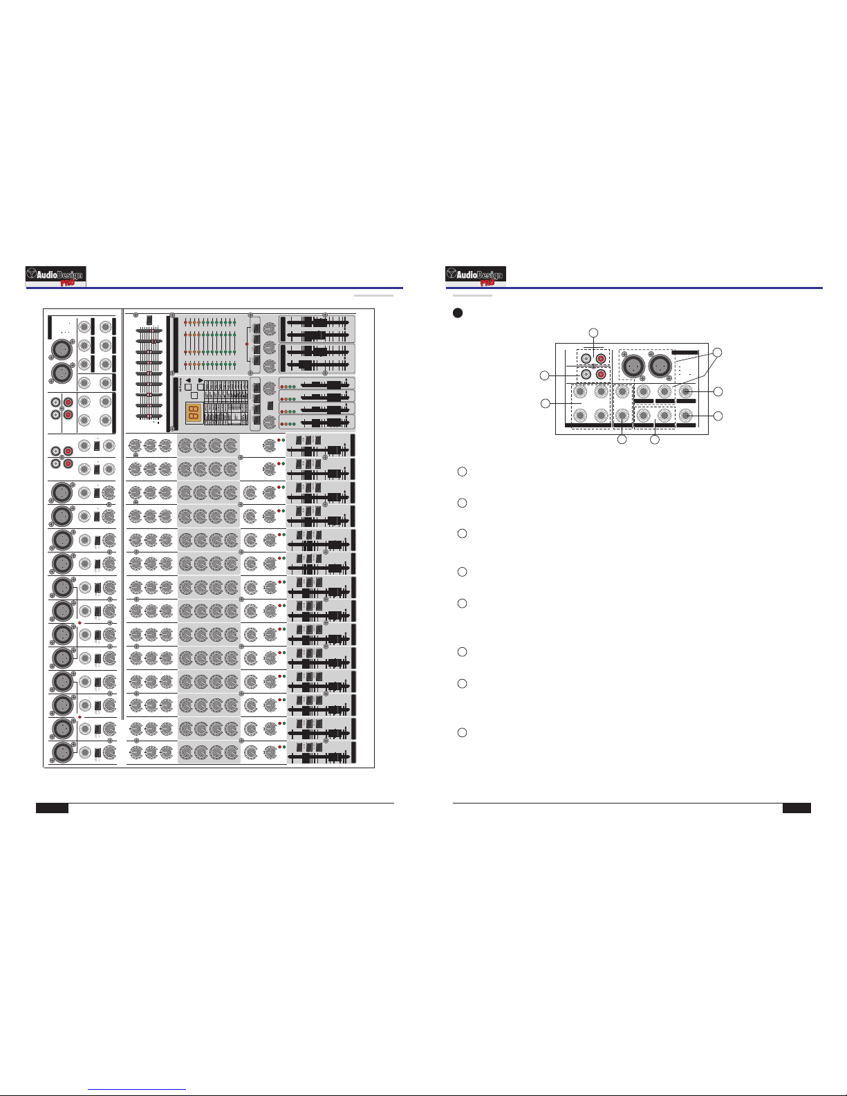
REAR PANEL/CONNECTION CABLES
UNBALANCED INPUTS
SHIELD
+ SIGNAL
BALANCED INPUTS
- SIGNAL
SHIELD + SIGNAL
INSERTS
SEND
SHIELD
RETURN
BALANCED MIC INPUT
PIN1: SHIELD
PIN2: + SIGNAL
PIN3: - SIGNAL
LINE
MIC9
GAIN
-10
dB
HI
MID
LOW
AUX1
AUX2
AUX3
AUX4
EFF
BAL
+20 +6 0
-1 5 +15
-1 5 +15
-1 5 +15
010
010
010
010
010
LR
PK
SIG
MIC
ST
9/10
PFL
SUB
MAIN
10
-50
-30
-20
-15
-10
PK
SIG
9/10
0
1
2
3
1
2
3
3
4
1
2
5
6
7
9
12
13
11
8
14
10
1~4 channel
+48V
PHAN TOM
5~8 channel
+48V
PHAN TOM
CH1
INSE RT
CH2
INSE RT
CH3
INSE RT
CH4
INSE RT
CAUTION: FOR CONTINUED
PROTECTION AGAINST RISK OF
FIRE REPLACE WITH SAME TYPE
AND VALUE FUSE INDICATED.
WARNING: TO REDUCE THE RISK
OF FIRE OF ELECTRIC SHOCK, DO
NOT EXPOSE HIS APPLIANCE TO
RAIN OR MOISTURE.
POWE R
FUSE : T0.5A
NO USER SERVICEABLE PARTS
INSIDE. REFER SERVICING TO
QUALIFIED SERVICE PERSONNEL.
USE ONLY WITH 25 0V FUSE
1
2
34
CH1~CH4 INSERT:
2
These four INSERT are a break point in the input channel signal path. It allows the signal to be taken
out from the mixer, through an external equipment such as a compressor, and than back to the mixer
to continue the final mix output.
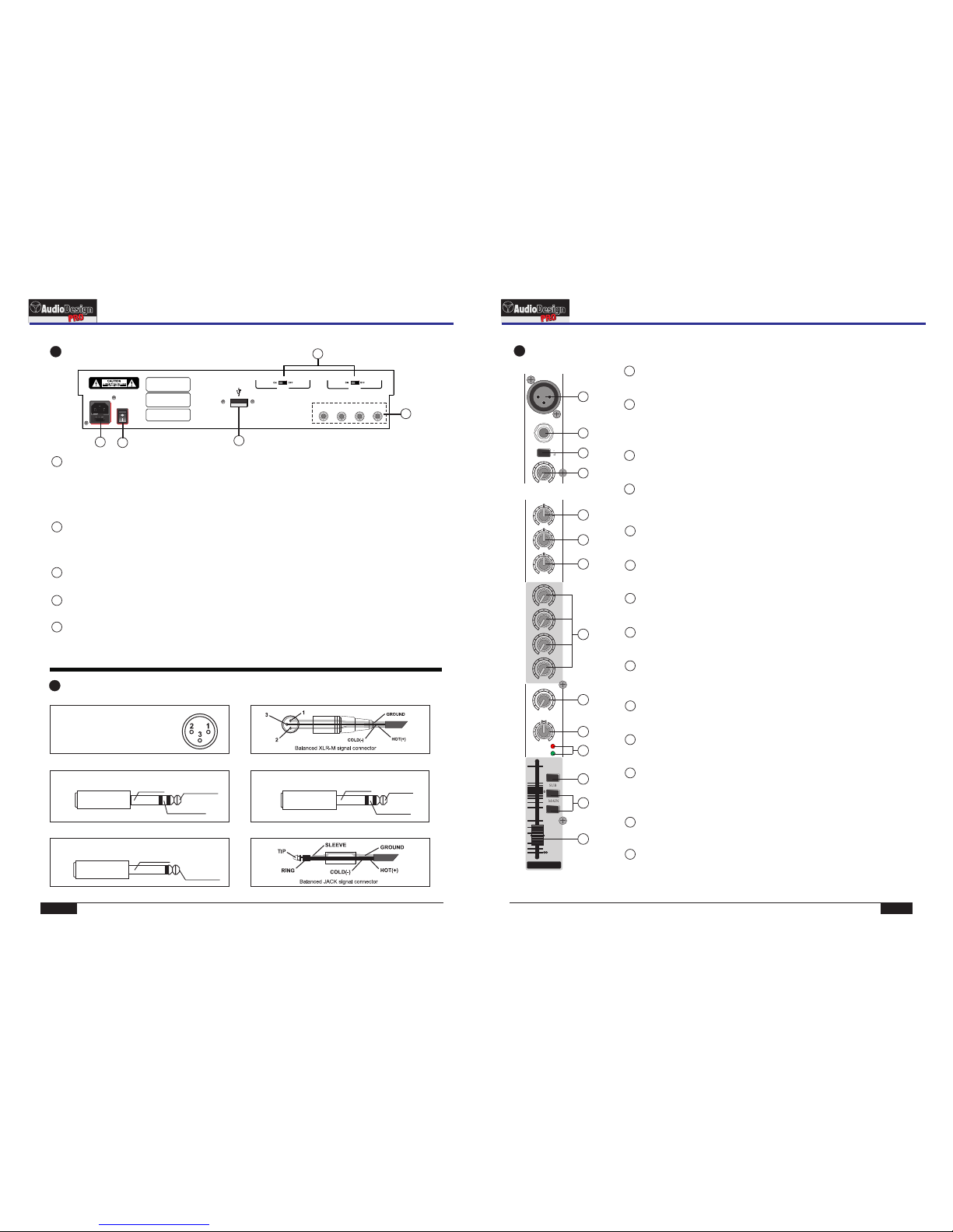
The stereo channel(A)
1MIC microphone input
This is an XLR type balanced connector for microphone,the input level range: -60~-
20dB. At this channel the amplified signal will be feed to the L/R main bus equally finally.
ST LINE IN Line input:
2
This is one unbalanced phone jacks to which line level devices can be connected, the
rated input level is -10dB. The tip of JK socket is used for Left input channel, and the
ring of JK socket is used for Right input channel, When you connect the socket’s tip
and ring, the right signal will be same as the left.
3-10dB attenuation switch
Press this knob, the input signal will be attenuated 10dB, when the input signal level is
too strong.
10 BAL:
This knob is used for controlling the stereo signal of the channel feed to L/R buses as
some proportion to balance the stereo sound image.
HI :
5
This knob control the frequency equalizer at higher frequency point.
Max adjust range: 15dB @ 12KHz±
MID
:
6
This knob control the frequency equalizer at middle frequency point.
Max adjust range: ±15dB @ 2.5KHz
LOW:
7
This knob control the frequency equalizer at lower frequency point.
Max adjust range: ±15dB @ 80Hz
AUX1,AUX2,AUX3,AUX4:
8
These 4
set in front of the channel fader, so they are not dependent on the fader position.
knobs are used for controlling the signal level feed to AUX1~4 bus, these 4 parts are all
EFF:
9
This knob is used for controlling the signal level feed to EFF bus, it has been set after
the channel fader, so it is enslaved to the fader position. Adjust these knobs when you
use effector on this channel.
11
CHANNEL FADER:
This fader controls the output level feed to main bus from the input channel, adjusting the volume
balance between channels. Faders of channels not in use should be pulled down.
12 SIG,PEAK Indicador:
These two LED indicators detect the signal level which exists at the end of the
channel but in front of the channel fader. SIG LED flashing means the channel is in
normal, and PEAK LED will be light at 6dB before clipping to remind that the signal
level is too strong to the unit will be overload.
13 PFL :switch
This switch allows you to monitor the signal of the input channel, the signal is
sampled in front of the channel fader, so it has nothing to do with the fader position.
14 SUB,MAIN channel output control:
These two switches control if the channel signal will feed to the SUB and MAIN bus
or not separately. The switch should be turned off for unused channels.
4GAIN control
Use this knob to adjust the level of the input signal to the optimal level. For the best
balance of S/N ratio and dynamic range, adjust this knob so that the peak indicator 12
lights occasionally.
1PHANTOM +48V phantom power switch and indicator
This button switch is used for turning on or off the +48V phantom power in the unit. The +48V phantom
power will exist on the input socket of each microphone input channel when this switch is pressed.
Notices: Slide down all channel fader before turning on or off the switch;
Don't plug or unplug microphone after this switch were turned on;
Don't turn on the phantom switch when a dynamic microphone is in use.
3
This AC power supply socket has a fuse-holder, use this socket to connect the AC power outlet.
POWER SOCKET & FUSE HOLDER:
4
Used for turn on/off the unit.
AC POWER SWITCH
Rear panel
Connection cables
5
USB port:
5
This USB jack is a communication port by which the USB audio interface of the mixer can carry data
with a computer . The computer in use do not need any drive soft, plug and play, also it provides
power for the USB audio interface at the same time.
PROFESSIONAL MIXER
Serie PAMX3
PROFESSIONAL MIXER
Serie PAMX3

PAGE 11
EFFECT LIST
PAGE 6
1
3
-10
dB
HI
MID
LOW
AUX1
AUX2
AUX3
AUX4
BAL
R
L
L
R
ST LINE 13/14
-1 5 +15
-1 5 +15
-1 5 +15
010
010
010
010
LR
PK
SIG
PFL
SUB
MAIN
10
-50
-30
-20
-15
-10
PK
SIG
13/14
0
11
12
4
2
5
6
7
8
9
10
REVERB HALL
2.0 S
2.5 S
3.0 S
4.0 S
5.0 S
6.0 S
8.0 S
01
02
03
04
05
06
07
08 10.0 S
REVERB ROOM
1.0 S
1.5 S
2.0 S
2.5 S
3.0 S
09
10
11
12
13
14 4.0 S
REVERB PLATE
1.0 S
1.5 S
2.0 S
2.5 S
3.0 S
15
16
17
18
19
20 4.0 S
AMBIENT
0.5 S
0.7 S
1.0 S
1.3 S
21
22
23
24
25 1.6 S
GATED REVERB
75 MS
100 MS
125 MS
150 MS
200 MS
26
27
28
29
30
31 300 MS
REVERSE REVERB
75 MS
100 MS
125 MS
150 MS
200 MS
32
33
34
35
36
37 300 MS
VOICE DOUBLER
60 MS
80 MS
100 MS
120 MS
38
39
40
41
42 140 MS
ECHO & ROOM 0.1/1.0 S
43
44 0.15/1.5 S
ECHO & HALL
0.2/2.0 S
0.25/2.5 S
0.3/3.0 S
0.35/3.5 S
0.4/4.0 S
45
46
47
48
49
50 0.5/5.0 S
ECHO 50% FB
100 MS
125 MS
150 MS
200 MS
250 MS
300 MS
350 MS
400 MS
500 MS
650 MS
51
52
53
54
55
56
57
58
59
60
61 800 MS
SINGLE DELAY
50 MS
100 MS
150 MS
200 MS
250 MS
300 MS
400 MS
62
63
64
65
66
67
68
69 500 MS
CHORUS FAST &ECHO 0.1 S
70
71
72 &ROOM 1 S
CHORUS MED &ECHO 0.2 S
73
74
75 &HALL 2 S
CHORUS SLOW &ECHO 0.3 S
76
77
78 &HALL 4 S
FLANGER FAST &ECHO 0.1 S
79
80
81 &ROOM 1 S
FLANGER MED &ECHO 0.2 S
82
83
84 &HALL 2 S
FLANGER SLOW&ECHO 0.3 S
85
86
87 &HALL 4 S
TREMOLO FAST
88
89 &ROOM 1 S
TREMOLO MED
90
91 &HALL 2 S
TREMOLO SLOW
92
93 &HALL 4 S
WAH WAH FAST
94
95 &ROOM 1 S
WAH WAH MED
96
97 &HALL 2 S
WAH WAH SLOW
98
99 &HALL 4 S
99 preset DSP effect list
1L left line input
These are two unbalanced connectors to which the left of a line level device can be
connected, the rated input level is -10dB.
Here it is convenient for selecting RCA connector or phone jack.
2R Right line input
These are two unbalanced connectors to which the right of a line level device can be
connected, the rated input level is -10dB.
Here it is convenient for selecting RCA connector or phone jack.
3-10dB attenuation switch
Press this knob, the input signal will be attenuated 10dB, when the input signal level is
too strong.
8 BAL:
This knob is used for controlling the stereo signal of the channel feed to L/R buses as
some proportion to balance the stereo sound image.
HI :
4
This knob control the frequency equalizer at higher frequency point.
Max adjust range: 15dB @ 12KHz±
MID
:
5
This knob control the frequency equalizer at middle frequency point.
Max adjust range: ±15dB @ 2.5KHz
LOW:
6
This knob control the frequency equalizer at lower frequency point.
Max adjust range: ±15dB @ 80Hz
AUX1,AUX2,AUX3,AUX4:
7
These 4
set in front of the channel fader, so they are not dependent on the fader position.
knobs are used for controlling the signal level feed to AUX1~4 bus, these 4 parts are all
10
CHANNEL FADER:
This fader controls the output level feed to main bus from the input channel, adjusting the volume
balance between channels. Faders of channels not in use should be pulled down.
9SIG,PEAK Indicador:
These two LED indicators detect the signal level which exists at the end of the
channel but in front of the channel fader. SIG LED flashing means the channel is in
normal, and PEAK LED will be light at 6dB before clipping to remind that the signal
level is too strong to the unit will be overload.
11 PFL :switch
This switch allows you to monitor the signal of the input channel, the signal is
sampled in front of the channel fader, so it has nothing to do with the fader position.
12 SUB,MAIN channel output control:
These two switches control if the channel signal will feed to the SUB and MAIN bus
or not separately. The switch should be turned off for unused channels.
The stereo channel(B)
CONTROL PANEL
PROFESSIONAL MIXER
Serie PAMX3
PROFESSIONAL MIXER
Serie PAMX3
PAGE 7PAGE 10
LR
REC OUT LR
BALANCED BALANCED
2TK IN
LR
AUX1
L/MONO
R
AUX SEND AUX RET
1 GROUND
2 HOT (+)
3 COLD ( )
SUB2 OUT PHONESSUB1 OUT
MAIN R OUT EFF SENDMAIN L OUT
MAIN OUT
AUX2
AUX3 AUX4
1
2
3
1
2
3
1
2
3
1
2
3
1
2
3
4
5
6
8
7
SET UP MEMO CONTROL PANEL
Control panel
1REC OUT:
These two RCA connectors can output low level stereo signal (left and right) for tape recorder.
3MAIN OUT (L, R)
These four connectors are all main output sockets of this mixer, two XLR connectors are balanced and two phone
jacks are unbalanced.
4SUB OUT1,2 group output sockets
These two connectors are group output sockets of this mixer, they are unbalanced.
5HEADPHONE stereo headphone socket
A set of stereo headphones can be connected to this phone jack. Normally, the headphones can monitor the same
signal as which sent to the each channel, when any PFL switch is pressed, the signal of the input channel after the
equalizer will be monitored.
AUX1~4 SEND:
8
These are unbalanced phone jacks for sending auxiliary output signals. They can be linked to a monitor outside or
linked to a sub power amplifier.
2TK IN:
2
These two RCA for the play input signal, rate input level: -10dB.connectors are unbalanced input
6
EFF SEND :
This is jack to send the output signals to the external effector.
AUX RET:
7
These are two auxiliary input phone jacks. The rated input level is -10dB.
Only connect the output of your source device to L/MOMO if the source is mono, thus the right signal is same as
the left.
PROFESSIONAL MIXER
Serie PAMX3
PROFESSIONAL MIXER
Serie PAMX3
LINE LINELINE
MIC9 MIC10
GAINGAIN
-10 -10 -10 -10
dB dB dB dB
HI HI HI HI
MID MIDMID MID
LOW LOW LOW LOW
AUX1 AUX1 AUX1 AUX1
AUX2 AUX2 AUX2 AUX2
AUX3 AUX3 AUX3 AUX3
AUX4 AUX4 AUX4 AUX4
EFF EFF
BAL BAL BAL BAL
R
L
R
L
L
R
L
R
ST LINE 15/16
ST LINE 13/14
LR
REC OUT LR
BALANCED BALANCED
2TK IN
LR
AUX1
L/MONO
R
AUX SEND AUX RET
0
+6
+12
0
+6
+12
1KHz 2KHz 4KHz 8KHz 16KHz500Hz250Hz125Hz63Hz
EQ
ON
MAIN L MAIN R/PFL SUB 1 SUB 2
6
12
6
12
1 GROUND
2 HOT (+)
3 COLD ( )
SUB2 OUT PHONESSUB1 OUT
MAIN R OUT EFF SENDMAIN L OUT
PFL
MAIN SUB AUX1/2 AUX3/4
EFF TO PHONES SELECTOR
+20 +60 + 20 +60
-1 5 +15 - 1 5 +15 -1 5 +15 - 1 5 +15
-1 5 +15 -1 5 +15-1 5 +15 -1 5 +15
-1 5 +15 - 1 5 +15 -1 5 +15 - 1 5 +15
010 010 010 010
010 010 010 010
010 010 010 010
010 010 010 010
010 010
LRLRLRLR
PK PK PK PK
SIG SIG SIG SIG
010 010 010 010 01 0
MAIN OUT
AUX2
AUX3 AUX4
MAIN SUB AUX1/2 AUX3/4
EFF SEND 2TK IN AUX RETEFF LEVEL PHONES
STEREO GRAPHIC EQUALIZER
PO FES SI ONA L MIX ER
OUTPUT LEVEL INDICATOR
MICMIC
ST ST
9/10 11/12
PFL
DSP EFFECTS PROCESSOR
MUTE
+10
+7
+4
+2
0
-2
-4
-7
-20
-10
-30
-38
+10
+7
+4
+2
0
-2
-4
-7
-20
-10
-30
-38
PFL PFL PFL PFL
SUB SUB SUB SUB
MAIN MAIN MAIN MAIN
10 10 10 10
-50 -50 -50 -50
-30 -30 -30 -30
-20 -20 -20 -20
-15 -15 -15 -15
-10 -10 -10 -10
11/12
10 10
-50
-30
-20
-15
-10
PK PK PK PK
SIG SIG SIG SIG CLIP CLIP CLIP CLIP
+6 +6 +6 +6
0 0 0 0
-20 -20 -20 -20
10 10 10 10
-50 -50 -50 -50
-30 -30 -30 -30
-20 -20 -20 -20
-15 -15 -15 -15
-10 -10 -10 -10
AUX1 AUX2 AUX3 AUX4 L
MAIN
R
SUB
12
15/16
13/14
0 0 0 0 0
0 0 0 0
-50
-30
-20
-15
-10
0
1
2
3
1
2
3
1
2
3
1
2
3
1
2
3
1
2
3
1
2
3
1
2
3
LINE LINE LINE LINE LINE LINE LINE LINE
MIC1 MIC2 MIC3 MIC4 MIC5 MIC6 MIC7 MIC8
GAIN GAIN GAIN GAIN GAIN GAIN GAIN GAIN
LOW
CUT
LOW
CUT
LOW
CUT
LOW
CUT
LOW
CUT
LOW
CUT
LOW
CUT
LOW
CUT
HI HI HI HI HI HI HI HI
MID MID MID MID MID MID MID MID
LOW LOW LOW LOW LOW LOW LOW LOW
AUX1 AUX1 AUX1 AUX1 AUX1 AUX1 AUX1 AUX1
AUX2 AUX2 AUX2 AUX2 AUX2 AUX2 AUX2 AUX2
AUX3 AUX3 AUX3 AUX3 AUX3 AUX3 AUX3 AUX3
AUX4 AUX4 AUX4 AUX4 AUX4 AUX4 AUX4 AUX4
EFF EFF EFF EFF EFF EFF EFF EFF
PAN PAN PAN PAN PAN PAN PAN PAN
+20 +60 + 20 +60 +20 +60 + 20 +60 +20 +60 + 20 +60 +20 +60 + 20 +60
-1 5 +15 - 1 5 +15 -1 5 +15 - 1 5 +15 -1 5 +15 - 1 5 +15 -1 5 +15 - 1 5 +15
-1 5 +15 - 1 5 +15 -1 5 +15 - 1 5 +15 -1 5 +15 - 1 5 +15 -1 5 +15 - 1 5 +15
-1 5 +15 - 1 5 +15 -1 5 +15 - 1 5 +15 -1 5 +15 - 1 5 +15 -1 5 +15 - 1 5 +15
010 010 010 010 01 0 010 010 010
010 010 010 010 01 0 010 010 010
010 010 010 010 01 0 010 010 010
010 010 010 010 01 0 010 010 010
010 010 010 010 01 0 010 010 010
LRLRLRLRLRLRLRLR
PK PK PK PK PK PK PK PK
SIG SIG SIG SIG SIG SIG SIG SIG
+48V +48V
PHA NTOM PHA NTOM
PFL PFL PFL PFL PFL PFL PFL PFL
SUB SUB SUB SUB SUB SUB SUB SUB
MAIN MAIN MAIN MAIN MAIN MAIN MAIN MAIN
10 10 10 10 10 10 10 10
-50 -50 -50 -50 -50 -50 -50 -50
-30 -30 -30 -30 -30 -30 -30 -30
-20 -20 -20 -20 -20 -20 -20 -20
-15 -15 -15 -15 -15 -15 -15 -15
-10 -10 -10 -10 -10 -10 -10 -10
123 4 5 6 78
PK PK PK PK PK PK PK PK
SIG SIG SIG SIG SIG SIG SIG SIG
0 0 0 0 0 0 0 0
1
2
3
1
2
3
1
2
3
1
2
3
1
2
3
1
2
3
1
2
3
1
2
3
1
2
3
1
2
3
1
2
3
1
2
3
1
2
3
1
2
3
1
2
3
LINE LINE
MIC7 MIC8
GAIN GAIN
LOW
CUT
LOW
CUT
HI HI
MID MID
LOW LOW
AUX1 AUX1
AUX2 AUX2
AUX3 AUX3
AUX4 AUX4
EFF EFF
PAN PAN
+20 +60 + 20 +60
-1 5 +15 - 1 5 +15
-1 5 +15 - 1 5 +15
-1 5 +15 - 1 5 +15
010 010
010 010
010 010
010 010
010 010
LRLR
PK PK
SIG SIG
PFL PFL
SUB SUB
MAIN MAIN
10 10
-50 -50
-30 -30
-20 -20
-15 -15
-10 -10
910
PK PK
SIG SIG
0 0
1
2
3
1
2
3
1
2
3
17/18
0
+6
+12
1KHz 2KHz 4KHz 8KHz 16KHz
EQ
ON
MAIN L MAIN R/PFL SUB 1 SUB 2
6
12
PFL
PHONES SELECTOR
010 010 010
MAIN SUB AUX1/2 AUX3/4
2TK IN AUX RET PHONES
OUTPUT LEVEL INDICATOR
10 10
-50
-30
-20
-15
-10
L
MAIN
R
SUB
12
0
-50
-30
-20
-15
-10
0
+10
+7
+4
+2
0
-2
-4
-7
-20
-10
-30
CLIP
+10
+7
+4
+2
0
-2
-4
-7
-20
-10
-30
CLIP
PAGE 9PAGE 8
0
+6
+12
500Hz250Hz125Hz63Hz
6
12
MAIN SUB AUX1/2 AUX3/4
EFF TO
010 010
EFF SEND EFF LEVEL
PFL
DSP EFFECTS PROCESSOR
MUTE
CLIP CLIP CLIP CLIP
+6 +6 +6 +6
0 0 0 0
-20 -20 -20 -20
10 10 10 10
-50 -50 -50 -50
-30 -30 -30 -30
-20 -20 -20 -20
-15 -15 -15 -15
-10 -10 -10 -10
AUX1 AUX2 AUX3 AUX4
0 0 0 0
9
11
17
12 13
14
16
15
10
PO F ES SI ON AL M IX E R
18
20
19
21
22
24
23
25 26
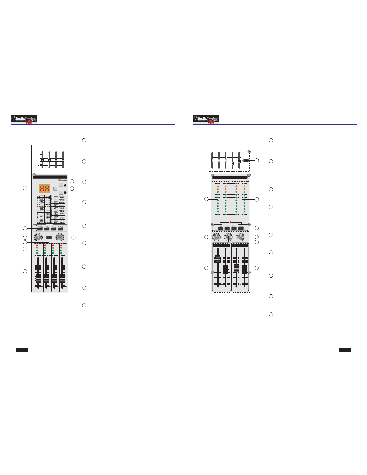
This knob used to control the input signal level from 2TK IN
sockets to main stereo bus and SUB group output.
24
2TK IN:
CONTROL PANEL
CONTROL PANEL
9
This double 7-segment LED display is used for indicating the
work state of the inner effector, and the corresponding effect
are shown as blow.
State display of inner effector:
10
These two buttons are used for selecting the states of the
inner effector.
Buttons for choosing the state:
EFF SEND:
12
This knob is used for controlling the signal level feed to the
inner effector from all input channels and also controlling the
signal level output from the EFF SEND sockets.
EFF LEVEL:
13
This knob is used for controlling volume of the signal level
from the output of the inner effector.
11
This button is used for muting the effect. When you press and
hold the button, the display will flash and the effect will be
muted until you loose the button.
MUTE:
14
This switch allows you to monitor the output signal of the inner
effector, the signal is sampled in front of the EFF fader, so it
has nothing to do with these fader position.
PFL :
15
AUX1~4 SEND:
These four faders are used for controlling the output level
from all input channel sent to the AUX1~4 SEND phone
jacks respectively.
16
These 4 level meters indicate the signal level of the
AUX1~AUX4 output
Level meter for AUX output:
EFF To EFFECT switch:
17
Press these 4 switch, can feed the effect signal to MAIN
OUT, SUB OUT, AUX OUT1/2 and AUX OUT3/4 respectively.
20 Level meter for SUB1,SUB2 group output
This level meter indicates the signal level of the group
output (SUB1 and SUB2).
21
PHONES SELECTOR :
When no channel PFL switch is pressed, these 4 buttons
choose whitch signal feed to headphone monitor. When
one channel PFL switch is pressed, you can hear the
pressed channel signal sampled in front of this channel
fader.
22
PHONES volume control:
This knob controls the volume of the headphones
connected to the headphone jack.
23
AUX RET :
This knob control the input level from an external
processor as external effector etc. connected to AUX
RETURN. The signal will be feed to stereo main bus and
sub bus.
25
Stereo L/R master control:
These two slide faders are used for adjusting the final
output level sent to the stereo output sockets.
26
SUB1, SUB2 group output control:
These two slide faders are used for adjusting the final
output level sent to the group output sockets.
18 Graphic equalizer and EQ ON switch:
This 9-band stereo graphic equalizer will be inserted in the
main output stage, when the EQ ON button is pressed.
19 Level meter for output:L,R/PFL
This level meter indicates the signal level of the stereo
main output (Left, Right and PFL). When a PFL button is
pressed, PFL LED light, the Right channel level indicator
turned into input signal level indicator of this channel.
PROFESSIONAL MIXER
Serie PAMX3
PROFESSIONAL MIXER
Serie PAMX3
This manual suits for next models
1
Table of contents
Other Audiodesign Music Mixer manuals


