Architectural Acoustics PZS 140RA User manual

Intended to alert the user to the presence of uninsulated “dangerous voltage” within the product’s
enclosure that may be of sufficient magnitude to constitute a risk of electric shock to persons.
Intended to alert the user of the presence of important operating and maintenance (servicing)
instructions in the literature accompanying the product.
CAUTION: Risk of electrical shock DO NOT OPEN!
CAUTION: To reduce the risk of electric shock, do not remove cover. No user serviceable parts inside. Refer
servicing to qualified service personnel.
WARNING: To prevent electrical shock or fire hazard, do not expose this appliance to rain or moisture. Before
using this appliance, read the operating guide for further warnings.
Este símbolo tiene el propósito, de alertar al usuario de la presencia de “(voltaje) peligroso” sin ais-
lamiento dentro de la caja del producto y que puede tener una magnitud suficiente como para constituir
riesgo de descarga eléctrica.
Este símbolo tiene el propósito de alertar al usario de la presencia de instruccones importantes sobre la
operación y mantenimiento en la información que viene con el producto.
PRECAUCION: Riesgo de descarga eléctrica ¡NO ABRIR!
PRECAUCION: Para disminuír el riesgo de descarga eléctrica, no abra la cubierta. No hay piezas útiles dentro.
Deje todo mantenimiento en manos del personal técnico cualificado.
ADVERTENCIA: Para evitar descargas eléctricas o peligro de incendio, no deje expuesto a la lluvia o humedad
este aparato Antes de usar este aparato, Iea más advertencias en la guía de operación.
Ce symbole est utilisé dans ce manuel pour indiquer à l’utilisateur la présence d’une tension dangereuse
pouvant être d’amplitude suffisante pour constituer un risque de choc électrique.
Ce symbole est utilisé dans ce manuel pour indiquer à l’utilisateur qu’il ou qu’elle trouvera d’importantes
instructions concernant l’utilisation et l’entretien de l’appareil dans le paragraphe signalé.
ATTENTION: Risques de choc électrique NE PAS OUVRIR!
ATTENTION: Afin de réduire le risque de choc électrique, ne pas enlever le couvercle. Il ne se trouve à l’intérieur
aucune pièce pouvant être reparée par l’utilisateur. Confiez I’entretien et la réparation de l’appareil à un réparateur
Peavey agréé.
AVERTISSEMENT: Afin de prévenir les risques de décharge électrique ou de feu, n’exposez pas cet appareil à la
pluie ou à l’humidité. Avant d’utiliser cet appareil, lisez attentivement les avertissements supplémentaires de ce
manuel.
Dieses Symbol soll den Anwender vor unisolierten gefährlichen Spannungen innerhalb des Gehäuses
warnen, die von Ausreichender Stärke sind, um einen elektrischen Schlag verursachen zu können.
Dieses Symbol soll den Benutzer auf wichtige Instruktionen in der Bedienungsanleitung aufmerksam
machen, die Handhabung und Wartung des Produkts betreffen.
VORSICHT: Risiko Elektrischer Schlag! Nicht öffnen!
VORSICHT: Um das Risiko eines elektrischen Schlages zu vermeiden, nicht die Abdeckung enfernen. Es befinden
sich keine Teile darin, die vom Anwender repariert werden könnten. Reparaturen nur von qualifiziertem
Fachpersonal durchführen lassen.
ACHTUNG: Um einen elektrischen Schlag oder Feuergefahr zu vermeiden, sollte dieses Gerät nicht dem Regen
oder Feuchtigkeit ausgesetzt werden. Vor Inbetriebnahme unbedingt die Bedienungsanleitung lesen.

GGEENNEERRAALL CCAAUUTTIIOONNSS AANNDD WWAARRNNIINNGGSS!!
To prevent electrical shock or potential fire ha ards, do not expose the PZS 140RA to moisture or rain.
Before using this product, read the user manuals for further warnings and cautions.
The following cautions should be carefully observed when installing, wiring or using this product:
DO NOT use any other power supply or cable other than the one provided with this unit.
DO NOT remove the top cover of the unit. There are no user-serviceable parts inside. Refer service
to qualified personnel.
DO NOT use solvents or other cleaners to clean the unit. Basic external care requires only a damp
cloth. Disconnect the power supply cord before cleaning.
Read all safety and installation instructions and retain all documentation for further reference.
The PZS™140RA should be installed so that its mounting position does not interfere with proper
ventilation.
This product should not be installed or placed near a source of heat.
Power supply cords and associated connectors should be unplugged from the power source when
the unit is not used for long periods of time or will be stored.
If this product is to be mounted in an equipment rack, install rear support if required by the rack
manufacturer.
Care should be taken to ensure that the installation is clear of possible sources of contamination.
Make sure that the product’s ventilation openings are not exposed to possible sources of liquid,
gases, or other contaminant.
This product should be inspected by a qualified service technician if the power supply cord or con-
nector has been damaged, if the unit has been dropped, or if a foreign substance has gained access
to the interior electronic and electrical components.
The information contained in this manual is subject to change without notice. Peavey Electronics is not liable
for improper installation or configuration. The information contained herein is intended only as an aid to
qualified personnel in the design, installation and maintenance of engineered audio systems. The installing
contractor or end user is ultimately responsible for the successful implementation of these systems.
All creative content in this manual, including the layout, art design, content, photography, drawings, specifi-
cations and all other intellectual property is Copyright © 2003 Peavey Electronics Corporation. All Rights
Reserved.

PAGE 4 PZS™-140RA User Manual
Table of Contents
Table of Contents
Welcome......................................................................................5
What’s in the box?.........................................................................5
Description...................................................................................6
Features......................................................................................7
Applications..................................................................................7
Installation Precautions..................................................................8
Input Channel Features.................................................................
Output Bus Features.....................................................................10
Other Front Panel Features............................................................10
Power.........................................................................................11
Inputs........................................................................................12
Digital Remote Control..................................................................12
Zone Outputs..............................................................................13
Connections................................................................................14
Theory.......................................................................................15
Operation...................................................................................16
Setup/Recall...............................................................................17
Remote Control Configuration........................................................18
Configuration Table ........................................................1
Performance Specifications............................................................20
General Specifications..................................................................21
Block Diagram.............................................................................22

PZS™-140RA User Manual PAGE 5
Welcome
What’s in the box?
Welcome
Thank you for purchasing the Peavey Architectural Acoustics®PZS™
140RA multi-zone mixer/amplifier. This product is designed to provide
years of trouble-free operation and high quality audio performance. We
sincerely hope that you enjoy your new purchase and will find other
products in the Architectural Acoustics product line to supplement your
new amplifier. We are confident that you will find the PZS 140RA, and
other Architectural Acoustics products to be of the highest quality.
This manual was written to provide as much information as possible for
your new Architectural Acoustics product. It is our sincere desire that
you enjoy your purchase. We feel that the best way to fully enjoy any
purchase is to have an in-depth understanding of the product’s
features, functionality and performance characteristics. We wrote this
manual with that in mind. If you require additional information that this
manual does not provide, please let us know. We are always looking for
better ways to provide information about our products, and your input
is always appreciated. If you have a comment about this manual or
would like to make a suggestion, please write to: Peavey Electronics
Corp., Architectural Acoustics Division, 711 A St., Meridian MS, 3 301.
Thank you again for using Architectural Acoustics!
The PZS 140RA is packaged in a single container. This container
includes the following items:
1- Architectural Acoustics PZS 140RA multi-zone mixer/amplifier
1- IEC removable power supply line cord
(120 VAC Domestic, 230 VAC Export)
5- Five-screw removable Euro connectors
4- Eight-screw removable Euro connectors
1- User Manual/Literature Package
If any of these items are missing, please contact your Authorized
Architectural Acoustics contractor/dealer.
ENGLISH

PAGE 6 PZS™-140RA User Manual
Welcome
The PZS™140RA is a full-featured matrix mixer with four integral
35 Watt power amplifiers. The five-input, four-output architecture is
supported by a full mix matrix with microprocessor-based assignment,
store/recall functionality, front panel controls and support for the new
D-Series remote control network.
The compact 3U package features an intuitive front panel design with
easy access to zone assign buttons, EQ, input level and output drive
controls. Visual feedback is included for matrix routing assignment,
input and output audio level and paging mute for master channels.
Among the most exciting new features is integral support for the
D-Series D4S four-button control panel. The D4S provides remote
access to the PZS 140RA's matrix cross points and can be configured
for either "input to zone" (source select), or "zone from input" (zone
select) operation. Multiple D4S panels can be connected simultaneously
via the included D-Series RJ-45 network connector, making installation
simple and cost effective. The front panel assignment LEDs mirror
changes made by the remote controls, so monitoring the status of
remote operation is easily confirmed at the front panel.
The versatile PZS 140RA includes microphone and line level inputs
terminated on removable Euro connectors on each channel. In addition,
input Channels 3, 4 and 5 also include summing RCA connectors for
easily terminating consumer line-level sources for music playback
applications.
Integral gate dynamics are provided for vox ducking, with channels 1
and 2 configured as master inputs. These inputs feature additional front
panel benefits including a mute status LED and recessed threshold and
hold controls.
Each of the PZS 140RA's four output sections include a 35 Watt power
amplifier. In addition to a direct-coupled, 4 Ohm output, the PZS 140RA
also features transformer-coupled constant voltage (domestic: 25 Volt,
70 Volt; export: 70 Volt, 100 Volt) outputs, an 8 Ohm output and a
600 Ohm balanced line level output. All output section connections are
also on removable Euro connectors for easy installation and service.
The output section is supported by a simple front panel interface
including master level controls, signal presence and clipping LED
indicators and matrix bus assign buttons.
Description

PZS™-140RA User Manual PAGE 7
Features
Features
• Five input channels, assignable to any output
• Mic and line level inputs for each channel
• RCA stereo summing inputs (channels 3, 4 & 5)
• Four balanced (600 Ohm) line level outputs
• Four 35W power amplifiers
• 70V, 25V, 8 Ohm and 4 Ohm amplifier outputs domestic
• 100V, 70V, 8 Ohm and 4 Ohm amplifier outputs export
• Removable Euro connectors for all I/O
• Support for the D-Series D4S remote control panel
• Signal LED indicator on each input channel
• Zone assignment switches for each channel and output bus
• Adjustable threshold and paging hold (ch 1/2)
• Four master output level controls
• Signal and clipping LEDs on all outputs
• Defeatable 48-Volt phantom power on all microphone inputs
• Shelf, or rack-mountable fan-cooled package
• Rack kit included
Applications
The PZS™140RA is a great audio product with hundreds of possible
applications. The many applications where the PZS 140RA is an ideal
choice include:
• Retail
• Restaurants and bars
• Houses of worship
• Hotel meeting rooms
• Schools
• Multi-purpose facilities
• Gaming
• Institutional paging
• Communications
• Correctional facilities
• Professional complexes
• Residential
PAGE 8 PZS™-140RA User Manual
Cautions
Installation Precautions
The PZS™140RA is designed for shelf or rack-mount installation. The
unit is equipped with rubber feet for shelf or table top installations.
When using racks, we recommend commercial grade, EIA electronic
equipment racks. Installing this unit in non-EIA racks or in other
configurations is not recommended. Failure to install this product in
the proper enclosure may void your warranty.
The PZS 140RA is forced-air cooled, and care should be taken not to
block the air intake or exhaust path located on the sides of the unit.
When installed in EIA racks, the PZS 140RA requires a minimum of 2”
clearance on each side of the equipment rack for proper cooling. In
normal conditions, the unit can be installed in adjacent rack spaces
without additional venting. However, it is recommended that common
sense be applied to large installations where multiple units are mounted
in a single rack. It is generally accepted that a ratio of one vent for
every two units is a good rule of thumb for adequate performance. In
installations where adverse conditions exist, and room temperatures are
likely to rise, additional vents should be installed.
Several associated products may be used to complete a working system
using the PZS 140RA. This manual frequently makes reference to these
products, but does not provide specific configuration or installation
information on them. Please refer to the manuals on these products for
information. Every product must be properly installed for the PZS
140RA to operate in accordance with its published specification.
The information contained in this manual is subject to change without
notice. Peavey Electronics is not liable for improper installation or
configuration. The information contained herein is intended only as an
aid to qualified personnel in the design, installation and maintenance of
engineered audio systems. The installing contractor or end-user is
ultimately responsible for the successful implementation of these
systems.
The illustrations, drawings and renderings contained herein are NOT
drawn to scale.
The PZS 140RA can be installed
into any EIA rack with an internal
depth clearance of 18" or more.
This will allow plenty of space for
the unit and its associated wiring
harness at the rear of the rack.
Infrastructure is critical for imple-
menting reliable sound systems.
It is important that your conduit
systems, wire plants and connec-
tor complement are properly
designed and installed or your sys-
tem may perform at inferior levels.
PZS™-140RA User Manual PAGE 9
Front Panel Features
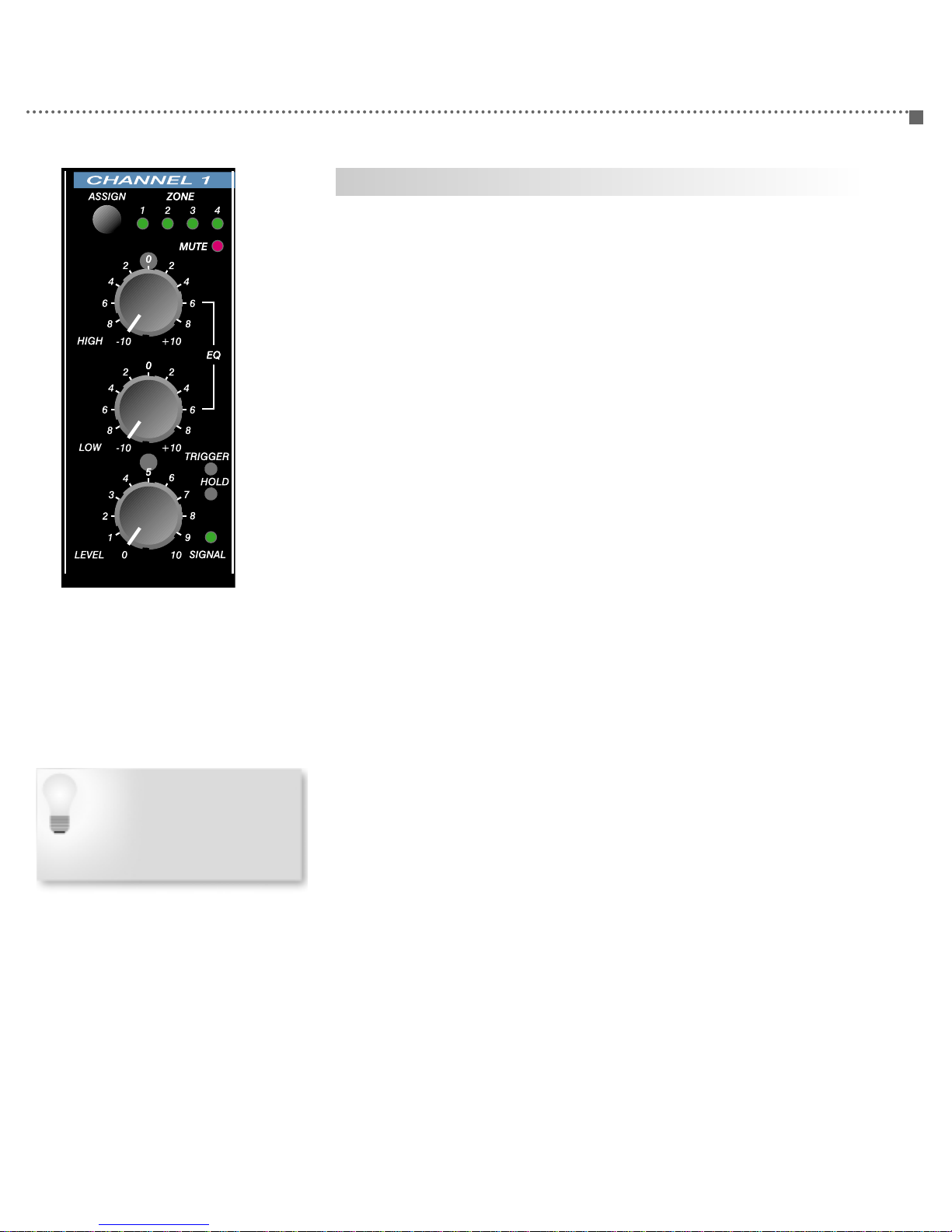
Input Channel Features
Each input Channel of the PZS™140RA includes identical control and
status functions. In addition, channels 1 and 2 include additional
TRIGGER and HOLD controls as well as MUTE LEDs to indicate the
status of the page ducking feature.
ASSIGN - Momentary push button, used in conjunction with the Zone
Assign button, assigns the input Channel to any combination output
zones. See page 17 for information on zone assignment and
configuration.
ONE - Single-color, green LEDs indicate Channel to Zone assignment.
The input Channel is routed to an output bus when the corresponding
ZONE LED is illuminated.
MUTE - (Channels 1 & 2 only) Red LED indicates that the Mute bus is
active. When input Channel 1 or 2 is active, all other channels will be
muted or ducked, depending on the position of the TRIGGER and HOLD
controls.
HIGH - Rotary control adjusts the level of the Channel’s high frequency
filter. The filter center is at 10 kHz. The control adjusts the filter
amplitude from unity (0) to either -10 dB or +10 dB.
LOW - Rotary control adjusts the level of the Channel’s low frequency
filter. The filter center is at 100 Hz. The control adjusts the filter
amplitude from unity (0) to either -10 dB or +10 dB.
LEVEL - Rotary control adjusts Channel input level. The level control is
active after the first gain stage, just before the EQ section.
TRIGGER - (Channels 1 & 2 only) Recessed rotary control adjusts the
audio level required (threshold) to activate the internal ducking/muting
circuit. Adjusting this control clockwise decreases the level required to
activate the ducking/muting circuit. To bypass the ducking/muting
feature, place this control in the maximum counter-clockwise position.
HOLD - (Channels 1 & 2 only) Recessed rotary control adjusts the
release time of the ducking/muting circuit. Adjusting this control
clockwise will increase the time required for the ducking circuit to
release.
SIGNAL - Green LED indicates audio input signal level. The LED
monitors input signal after the first gain stage, just before the LEVEL
control. The LED will illuminate green when the signal level is above
-20 dBu.
“Hold” is the time interval between
the last detectable (set by the
TRIGGER control) audio signal and
the release point of the ducking
circuit. The HOLD control adjusts
the release point, increasing or
decreasing the hold time interval.

PAGE 10 PZS™-140RA User Manual
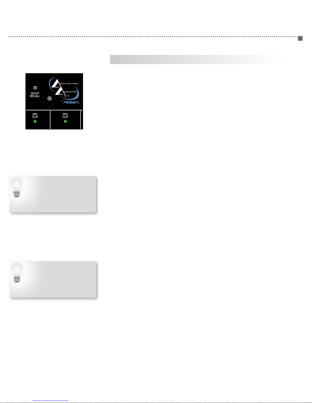
Other Front Panel Features
SETUP RECALL - Momentary push button allows for storage and recall
of a single assignment configuration. See page 18 for details on the
Setup Recall feature.
POWER - Green LED indicates the presence of AC power mains. This
LED will be illuminated when the rear panel power switch is in the ON
position.
Front Panel Features
Output Bus Features
Each output bus, referred to as a “Zone”, includes identical control and
status functions.
SIG CLIP - Bi-color LED indicates audio input signal level. The LED
monitors input signal after the summing bus and before the power
amplifier. The LED will illuminate red when the signal is above 85% of
rated power, indicating the onset of clipping.
LEVEL - Rotary control adjusts Channel input level. The LEVEL control
adjusts the audio signal after the summing bus and before the power
amplifier.
ASSIGN - Momentary push button, used in conjunction with the
Channel Assign button, assigns the input channel to any of the four out-
put buses.
PZS™-140RA User Manual PAGE 11
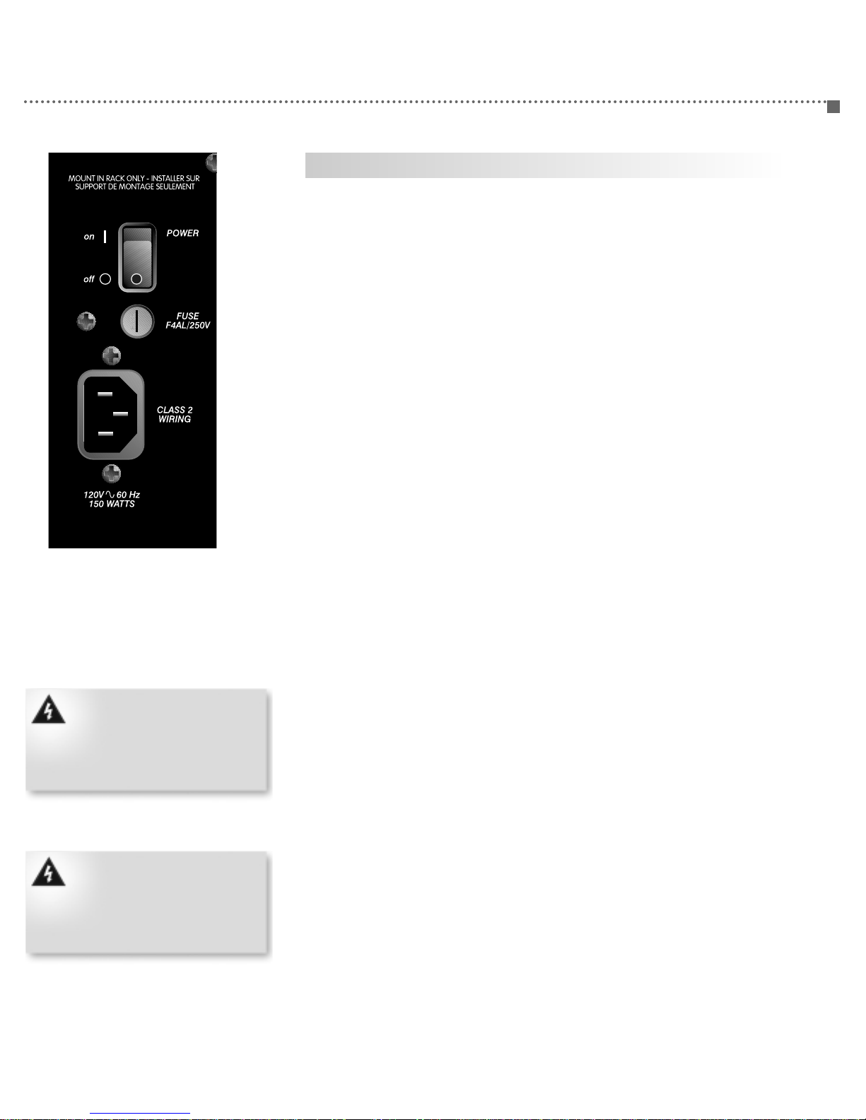
Rear Panel Features
Power
POWER - Two-position rocker switch enables mains AC power to the
unit. When the switch is in the ON position, the front panel POWER LED
will illuminate, indicating that the PZS™140RA is powered ON.
FUSE - Recessed receptacle houses main AC fuse. Fuse is a 250 Volt,
F4AL type single use fuse.
IEC CONNECTOR - Male IEC power connector for connecting supplied
IEC power cable.
FAN - The PZS 140RA is forced air-cooled and features a rear panel
intake fan. Do not block the fan or the exhaust vents.
Use only 250V, F4AL single use
fuses. Using any other type of
fuse is a safety hazard and may
cause damage to the equipment.
Use of improper fuse will void your
warranty.
Use only the supplied IEC power
cable or an equivalent of equal
size, length and rating. Using an
improper power cable may cause
damage to the equipment and
could void your warranty.
PAGE 12 PZS™-140RA User Manual
Rear Panel Features
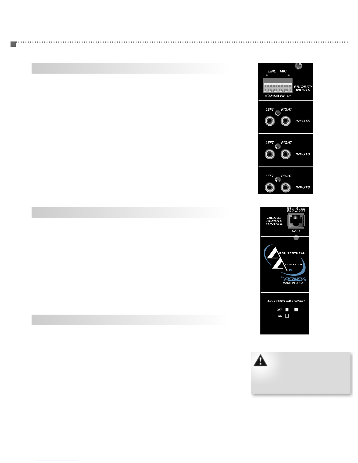
Inputs
Each channel of the PZS™140RA includes line-level and microphone-
level inputs. These inputs are terminated to removable Euro connectors
for balanced connections to external audio circuits. For information on
how to terminate a Euro connector, please see page 15.
Channels 1 and 2 are “priority” inputs and include special functionality
that allow them to be used as vox-based paging priority channels. This
functionality is controlled from the front panel TRIGGER and HOLD
controls. (See page 10.)
In addition to the line and mic-level inputs, channels 3, 4 and 5 include
dual female RCA connectors that include an internal summing network.
These inputs should be used with stereo (two-channel) line-level
sources with a nominal output level of -10 dBm.
Digital Remote Control
The PZS 140RA supports the Peavey Architectural Acoustics D-Series
D4S remote control panel. The D4S connects directly to the PZS 140RA
via the rear panel DIGITAL REMOTE CONTROL connector. This connector
is a female RJ-45 jack designed to connect the controllers using
standard Category 5 (CAT5) cable.
For more information on the DIGITAL REMOTE CONTROL feature, please
see page 1 .
Phantom Power
Pressing the 48 Volt Sub-panel switch activates the 48 Volt Phantom
Power on Mic inputs 1 through 5.
Each channel can receive only one
type of audio input at a time.
Terminating more than one source
signal to a single channel simulta-
neously will result in unsatisfactory
performance.
PZS™-140RA User Manual PAGE 13
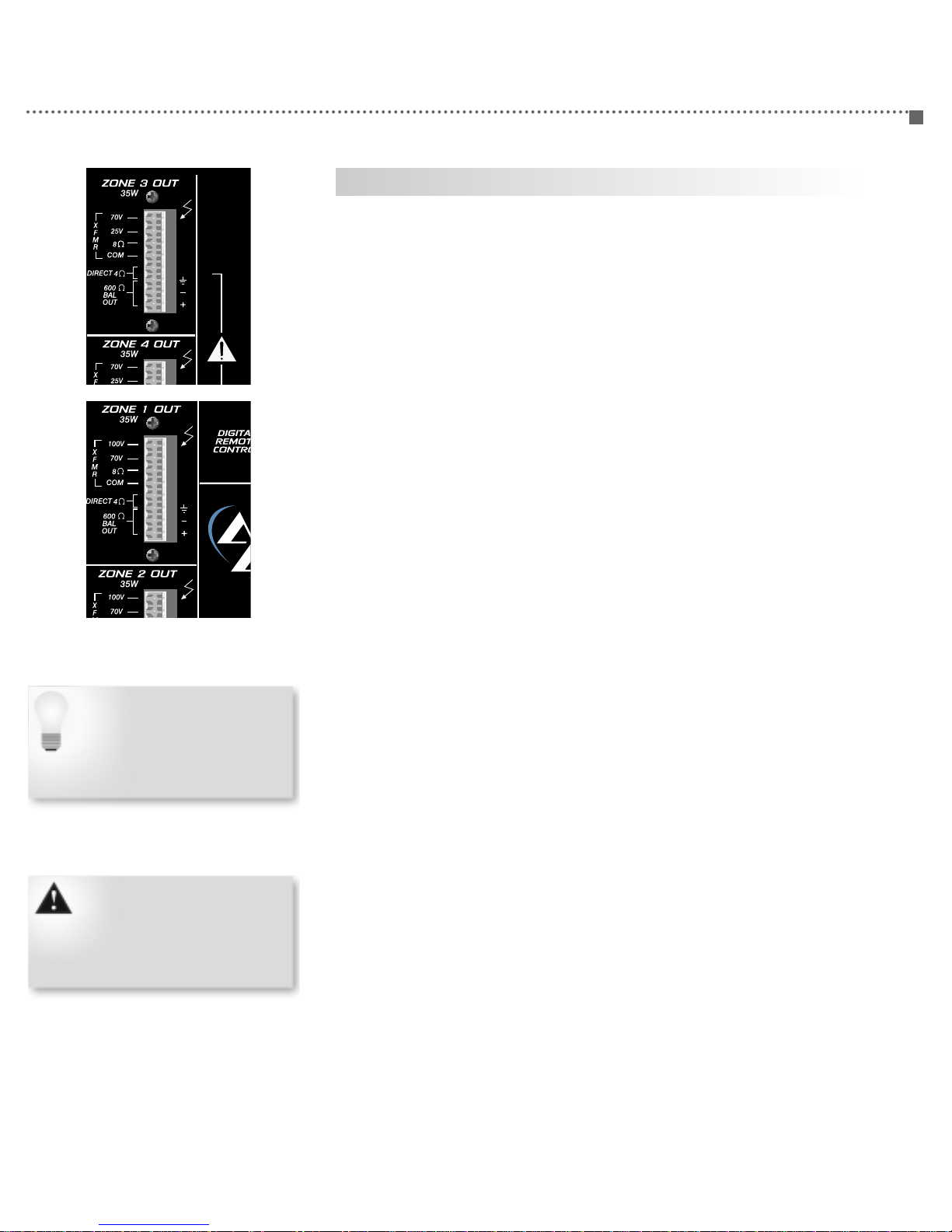
Zone Outputs
one Outputs
Each of the four PZS™140RA outputs includes identical features and are
labeled as “zones.” Both line-level and loudspeaker-level outputs are
provided. The power rating for the loudspeaker outputs is 35 Watts and
is transformer-coupled except for the 4 Ohm output.
XFMR - Each tap provides 35 Watts to constant voltage loads,
referenced to the COM connector. There are secondary transformer taps
for 70 Volt, 25 Volt and 8Ω loads (dom.) and 100 Volt, 70 Volt and 8Ω
loads (export).
DIRECT 4 OHM - This output is direct-coupled to the power amplifier
output and is referenced to ground.
600 OHM BAL OUT - Balanced 600 Ohm output for driving high
impedance sources. This signal is derived from the transformer
secondary and a passive line/impedance matching circuit. This output is
considered to be transformer-balanced and can be used simultaneously
with the loudspeaker-level output circuits.
The 600 Ohm BAL OUT output is
transformer coupled from the sec-
ondary of the output transformer.
This output can be used simulta-
neously with any of the other out-
puts.
Do not terminate more than one
transformer-coupled loudspeaker
output simultaneously. All trans-
former-coupled loads are refer-
enced to COM.
PAGE 14 PZS™-140RA User Manual
Connections
Connections
The PZS™140RA features a rear panel connection scheme and includes
the following connection types:
• Microphone-Level Audio Input
• Line-Level Audio Input
• Summing RCA Line-Level Input
• Digital Remote Control
• Transformer-Coupled Loudspeaker Output
• Direct-Coupled Loudspeaker Output
• Transformer-Coupled Line Level Output
Except for the Digital Remote Control and RCA Line-Level Inputs, all
connections are placed on Euro connector blocks designed for easy
termination, service and maintenance. The unit ships with a matching
pluggable connector for each header block. The preferred method for
making audio connections consists of four steps as detailed in the steps
below. All terminations are identical except for the connection type and
the number of conductors per circuit. As with any electronic connection,
care should be taken to ensure the termination is solid. For a proper
termination, there should be no stray wire strands, kinks or nicks in the
wire jacket. As always, audio connections should be made with high
quality stranded wire. Input connections should be shielded.
STEP 1. Carefully strip the cable jacket and the conductor insulation.
The distance between the end of the jacket and the tips of the
conductors should be approximately .750”. The strip length of the
conductor wire should be approximately .310” for proper termination
into the Euro connector.
STEP 2. Carefully insert each conductor into the opening of the Euro
connector. Take care to ensure that polarity is observed and that the
shield is properly twisted to make a solid connection. Ideally, the shield
should be isolated by installing heat shrink insulation.
STEP 3. While holding the cable so each conductor is firmly seated in
the connector, carefully tighten down each screw. While turning each
screw, look closely at the wire and make sure that the action of the
screw does not “push” the wire out of the connector. Verify the integrity
of your connection by gently pulling on each conductor to ensure that it
is terminated properly.
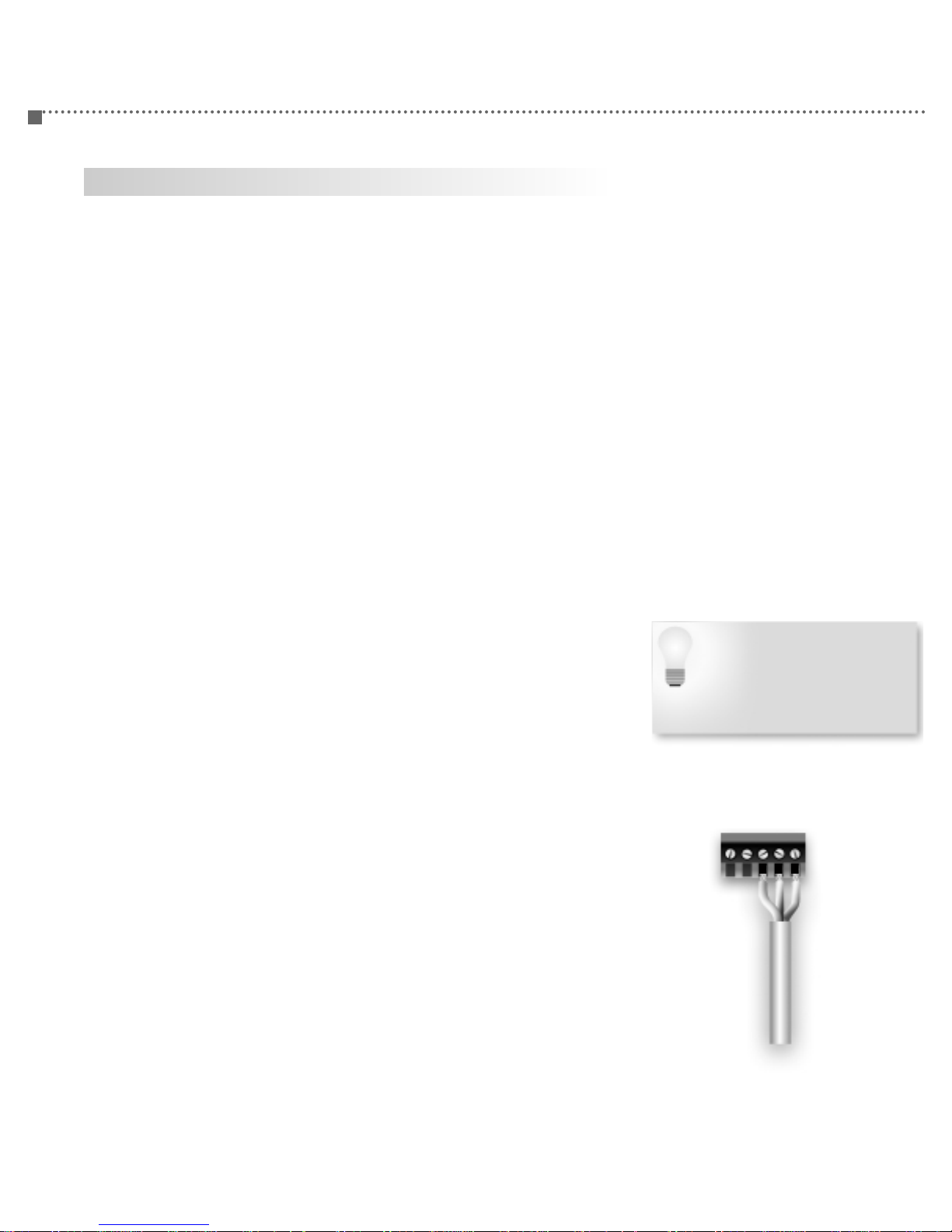
STEP 4. Take the completed wire/connector assembly and carefully
plug it into the matching connector header on the PZS 140RA’s rear
panel. Take care that you are plugging the connector into the proper set
of pins on the header. There is no barrier between adjacent audio
channels, so it is possible to connect to pins of an adjacent channel. If
you are not careful, instead of connecting to Positive, Negative and
Shield, you may end up connecting Negative-Shield-Negative. Your
finished connector for a single input circuit should look like the
illustration to the right.
The line-level Euro inputs will also
accept un-balanced circuits. To
terminate an unbalanced source,
use the ground and positive
terminals. It is NOT necessary to
use a jumper to bridge the shield
and negative conductor.

PZS™-140RA User Manual PAGE 15
Theory
Theory
The PZS™140RA is essentially a matrix mixer coupled with four 35 Watt
power amplifiers. To maximize the PZS 140RA for your application, it is
recommended that you have a solid understanding of signal flow, and
how the PZS 140RA provides processing, routing and output.
• INPUTS
The INPUT section includes five preamplifiers, each with their own
inputs and controls. The five inputs are basically stand-alone audio
blocks with a single output. The output terminates to the
microprocessor-controlled bus assign switches. (Each input has its own
set of bus assign switches.) The outputs of the switches connect
directly to the matrix buses.
• MATRIX
The MATRIX includes four buses that allows any of the five inputs to be
assigned to any of the four outputs. This assignment is configured by
using the ASSIGN buttons on the front panel. To simplify the
assignment process, there are buttons for each input and each output
in the matrix.
• OUTPUTS
There are four output sections. The key component of the output
section is the summing amplifier. All four of the matrix buses terminate
to the summing amplifier, which effectively is a 4x1 mixer at the front
of each output. The output section then drives the power amplifier
which includes direct and transformer-coupled output terminals.
The combination of the microprocessor-controlled switches at each input
section and the output summing amplifier creates the actual matrix
function of the PZS 140RA.

PAGE 16 PZS™-140RA User Manual
Operation
Operation
The primary function of the PZS™140RA is to operate as a matrix mixer,
as previously described. A matrix mixer includes “cross points” where
the input Channels are “connected” to the output buses, or in this case,
“zones”. Enabling the connection of the matrix cross point completes
the circuit between the input Channel and the output zone. (See block
diagram on page 22.)
Making this connection on the PZS 140RA is easy. Each input Channel
includes a momentary button and four-LED array. Each Zone includes a
single button. The cross point connection is enabled by using both the
Channel and Zone buttons.
To assign an Channel to a Zone, press and hold the ASSIGN button on
the desired Channel. While holding the button down, press and hold the
ASSIGN button on the target Zone until the corresponding Zone LED
illuminates on the channel’s LED array. Release both buttons to com-
plete the assignment.
The key to Zone assignment on the PZS 140RA is the LED array on
each input channel. The LEDs tell you to which output Zone the Channel
is assigned. Any combination of output assignment is possible, so more
than one LED can be illuminated.
To clear, or “dis-assign” an input channel to an output Zone, follow the
same process until the corresponding LED is OFF.
To assign an input channel to multiple Zones, follow the same process
for each output Zone.
The illustration below shows a PZS 140RA with channel 1 assigned to
Zone 2 and Zone 3, channel 2 assigned to Zone 1 and channel 3
assigned to Zone 4. Channels 4 and 5 are not assigned.
PZS™-140RA User Manual PAGE 17
Configuration
Use the Setup/Recall feature to
provide the end-user a “safety
net”. If the zone assignments are
altered, they can easily be
restored by recalling the original
configuration.
In the event of a power loss, using
the Recall feature is not necessary
to restore settings. The PZS 140RA
will revert to the last configuration
when power is restored; therefore,
no additional action is required.
Setup/Recall
On the front panel of the PZS™140RA, you will notice a small, recessed
button labeled “Setup/Recall”. This button provides access to
functionality that enables you to store a “snapshot” of the matrix
assignment buttons and recall them easily in the event of an
inadvertent reassignment.
The Setup/Recall feature includes two basic functions:
•Store
•Recall
The Store function allows you to write the current input assignment
locations to the PZS 140RA’s internal flash memory. This memory is
non-volatile, which means that even without power, the memory is
secure. The file that is written to memory includes the position of the
Assign buttons for each input Channel.
To store this file, follow these steps:
1. Configure the PZS 140RA for the zone assignment you wish to store.
Refer to page 17 for details on operation.
2. Using a small pen, or other instrument, press and hold the
Setup/Recall button. After a few seconds, the Mute LEDs on channels 1
and 2 will flash. Continue holding the button down until the flashing
stops.
3. Release the button. The configuration file is now written.
To recall this file, simply press (do not hold) the Setup/Recall button.
The LEDs will flash momentarily, indicating that the file was recalled
successfully.
The Setup/Recall feature stores a single configuration file. Usually, this
file would include the default configuration assignments for a project.
An example of this would be a restaurant, where the installing
contractor has assigned the input Channels to restaurant zones per
his/her contract. During normal use, the restaurant staff reassigns
certain inputs, but later realizes that the original configuration needs to
be restored. The Setup/Recall feature provides this functionality.

PAGE 18 PZS™-140RA User Manual
Configuration
When using the D4S with the PZS
140RA, the buttons always operate
as switches, and thus are not
mutually exclusive. This allows full
matrix assignment, just like the
front panel of the PZS 140RA.
Refer to the D-Series User Manual.
Remote Control Configuration
The PZS™140RA includes limited support for the D-Series remote
control network. Although the network is supported, only the D-Series
D4S is operable for the PZS 140RA. The D4S is a four-button, flush-
mount panel that can be configured to provide remote access to the
PZS 140RA’s matrix/assign functionality. Using the D4S provides a
simple way to provide a remote location access to input or zone
selection.
The D-Series network uses a system of Base Addresses to identify
control function on the network. You can connect up to 32 D4S panels
on a single PZS 140RA, but only eight Base Addresses are supported.
This means that you could have many duplicate panels operating in
“parallel” up to the 32 panel, eight Base Address limit. For more
information on the D-Series system, please refer to the D-Series User
Manual.
When a D4S panel is configured for input channel operation, the
buttons allow for zone selection. Conversely, when the D4S is
configured for zone operation, the buttons provide input channel
selection.
Although the D-Series network includes 32 Base Address options, only
eight are supported on the PZS 140RA. Assigning a D4S to one of these
eight Base Addresses will configure the panel as follows:
PZS™-140RA User Manual PAGE 19
Configuration Table
Base Address
1
17
33
4
65
25
41
57
Access
Zone
Zone
Zone
Zone
Zone
Channel
Channel
Channel
Channel
Description
Configures Channel 1 for Zone access
Configures Channel 2 for Zone access
Configures Channel 3 for Zone access
Configures Channel 4 for Zone access
Configures Channel 5 for Zone access
Configures Zone 1 for Channel access
Configures Zone 2 for Channel access
Configures Zone 3 for Channel access
Configures Zone 4 for Channel access
When the D4S is configured for
Zone operation, only input
channels 2-5 are accessible via the
buttons. Channel 1, intended for
priority operation, is not supported
in this mode.
D4S Configuration Table
Channel 1
1: ON
2: ON
3: OFF
4: OFF
5: OFF
6: OFF
7: OFF
8: OFF
Zone 1
1: ON
2: ON
3: OFF
4: On
5: OFF
6: OFF
7: OFF
8: OFF
Zone 2
1: ON
2: ON
3: OFF
4: On
5: OFF
6: OFF
7: OFF
8: OFF
Zone 3
1: ON
2: ON
3: OFF
4: ON
5: OFF
6: OFF
7: OFF
8: OFF
Zone 4
1: ON
2: ON
3: OFF
4: ON
5: ON
6: ON
7: OFF
8: OFF
Channel 2
1: ON
2: ON
3: OFF
4: OFF
5: ON
6: OFF
7: OFF
8: OFF
Channel 3
1: ON
2: ON
3: OFF
4: OFF
5: OFF
6: ON
7: OFF
8: OFF
Channel 4
1: ON
2: ON
3: OFF
4: OFF
5: ON
6: ON
7: OFF
8: OFF
Channel 5
1: ON
2: ON
3: OFF
4: OFF
5: OFF
6: OFF
7: ON
8: OFF

PAGE 20 PZS™-140RA User Manual
Specifications
Performance Specifications
Rated Power (individual 4 ohm load): 35 Watts @ 60 Hz to 20 kHz
<1% T.H.D., simultaneous operation (x4)
Minimum Load Impedance: 4 Ohms, direct coupled. 25V, 70V & 8
Ohms (domestic); 70V, 100V & 8 Ohms (export) transformer-coupled
Frequency Response: 60 Hz - 20 kHz; +0, -3 dB (transformer
coupled)
T.H.D., one channel driven: <0.05% @ 35 Watts @ 1 kHz
Inputs, channel 1 & 2:
Mic: 2k Ohm, -54 dBu (1.5mV, balanced)
Line: >50k Ohm, -18 dBu (100mV, balanced)
RCA: >50k Ohm, -18 dBu (100mV, balanced)
Signal to Noise Ratio:
Residual: (channel down, master full), 0 dB below rated power
Line Inputs: (controls nominal, 2k Ohm terminated), 0 dB below rated
power
Mic Inputs: (controls nominal, 150 Ohm terminated), 82 dB below rated
power
Tone Controls:
Low EQ: +10, -10 dB @ 100 Hz
High EQ: +10, -10 dB @10 kHz
Controls:
Channels 1 & 2: Level, Low EQ, High EQ, Assign, Signal Presence LED,
Mute LED, Threshold (trigger) Adjust, Hold/Release Time Adjust
Channels 3-5: Level, Low EQ, High EQ, Assign, Signal Presence LED
Notes:
1. All specifications are typical for any channel(s).
2. All measurements are made from analog input to analog output.
Typical performance reflects both input and output analog circuit
behavior.
3. All specifications are for an AC line input of 120 Volts RMS.
4. All output measurements are made using 4 Ohms unless otherwise
noted.
5. All input measurements are made using a 600 Ohm balanced source
impedance at 0 dBu unless otherwise noted.
6. All measurements are made with gain/attenuation set for maximum
unless otherwise noted.
Other manuals for PZS 140RA
1
Table of contents
Languages:
Other Architectural Acoustics Music Mixer manuals


