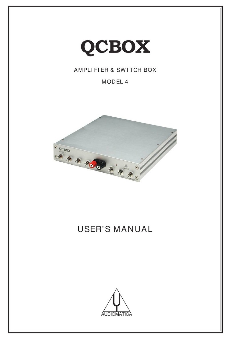
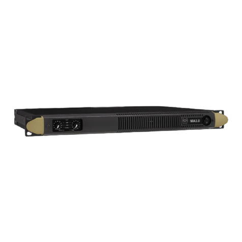
Audiomatica Qcbox 5 User manual

POWER AMPLIFIER, SWITCHING AND TESTING BOX
MODEL 5
USER'S MANUAL
AUDIOMATICA

© COPYRIGHT 1991-2011 BY AUDIOMATICA SRL
ALL RIGHTS RESERVED
EDITION 1.2, AUGUST 2011
IBM is a egiste ed t adema k of Inte national Business Machines Co po ation.
Windows is a egiste ed t adema k of Mic osoft Co po ation.
2

CONTENTS
1 - THE QCBOX MODEL 5 POWER AMPLIFIER, SWITCHING AND TESTING BOX..........4
2 - TECHNICAL SPECIFICATIONS.........................................................................5
3 - GENERAL CONDITIONS AND WARRANTY.........................................................6
4 - INTERNAL FUNCTIONAL DIAGRAM..................................................................7
5 - BASIC CONNECTIONS...................................................................................8
6 - DEFAULT INTERNAL SETTINGS.......................................................................9
7 - USB DRIVER INSTALLATION.........................................................................10
8 - SOFTWARE CONTROL..................................................................................19
9 - CALIBRATING SOFTWARE............................................................................20
10 - CONNECTING EXTERNAL HARDWARE..........................................................21
11 - CONNECTING A FOOT PEDAL SWITCH.........................................................21
12 - RACK MOUNT ASSEMBLY...........................................................................21
13 - INTERNAL SETTINGS AND TROUBLESHOOTING.............................................22
3

1 - THE QCBOX MODEL 5 POWER AMPLIFIER, SWITCHING AND
TESTING BOX
The QCBOX Model 5 powe amplifie , switching and testing box is of invaluable help in
eve yday labo ato y use and when configu ing an automatic o manual quality cont ol
setup.
The QCBOX Model 5 has an ult aslim design, enhanced featu es as USB connection to
the PC and DC measu ing capabilities with espect to its p edecesso model 4,
inc eased powe (50W@8Ohm) with espect to its p edecesso s Model 1, 2 & 3 and
wide ange AC (90÷240V) powe supply. The powe amplifie output cu ent is limited
unde softwa e cont ol.
Its main featu e is the possibility of in ernal swi ching, unde softwa e cont ol, that
pe mits the measu ement of the impedance and f equency esponse of the
loudspeake (o D.U.T.) connected to its output sockets without changing the
loudspeake (o D.U.T.) wi ing; it is also possible to choose one among fou inputs fo
the esponse measu ements; the inte nal switching is cont olled via a USB po t of the
PC. The inputs 3 and 4 can be also configu ed to measu e DC voltages with ange
±2.5V and ±5V espectively. Mo e than one unit can be used to oute mo e than fou
channels.
An inte nal softwa e cont olled voltage gene ato can supe impose a DC voltage
(±20V) to the amplifie voltage output, allowing fo loudspeake la ge signal
pa amete s measu ement.
A dedicated output, ISENSE, allows impedance measu ements in constant voltage
mode as well voice coil cu ent disto tion analysis. The ISENSE DC cu ent is
measu ed in a ange ±2.25A.
A dedicated input, PEDAL IN, pe mits an exte nal foot pedal switch o TTL signal to be
connected and t igge QC ope ations.
A DB25 connecto on the ea panel featu e 5 digital IN and 6 digital OUT.
4

2 - TECHNICAL SPECIFICATIONS
Inputs: Fou line/mic ophone inputs with selectable
phantom powe supply (0÷24V softwa e cont olled)
TTL pedal input (RCA connecto )
Digital I/O: 5 digital inputs (DB25 connecto )
6 digital outputs (DB25 connecto )
Powe output stage: 50W (8Ohm) powe amplifie (26dB gain) with cu ent sensing
and softwa e cont olled cu ent limite
Capability of supe imposing a DC voltage (±20V)
THD (@1 kHz): 0.004 %
Functions: USB cont olled inte nal switches fo impedance measu ements
Isense DC cu ent measu ement ±2.25A
DC IN measu ement (IN 3 ange ±2.5V, IN 4 ange ±5V)
Dimensions: 23(w)x23(d)x4(h)cm
Weight: 1.4kg
Powe supply: 150W 90÷240VAC
5

3 - GENERAL CONDITIONS AND WARRANTY
THANKS
Thankyou fo pu chasing you QCBox Model 5. We hope that you expe iences using
QCBox Model 5 will be both p oductive and satisfying.
CUSTOMER SUPPORT
Audiomatica is committed to suppo ting the use of the QCBox Model 5, and to that
end, offe s di ect suppo t to end use s. Ou use s all a ound the wo ld can contact us
di ectly ega ding technical p oblems, bug epo ts, o suggestions fo futu e softwa e
enhancements. You can call, fax o w ite to us at:
AUDIOMATICA SRL
VIA MANFREDI 12
50136 FLORENCE, ITALY
PHONE: +39-055-6599036
FAX: +39-055-6503772
AUDIOMATICA ON-LINE
Fo any inqui y and to know the latest news about the QCBox Model 5 and othe
Audiomatica’s p oducts we a e on the Inte net to help you:
AUDIOMATICA website: www.audiomatica.com
E-MAIL: [email protected]
AUDIOMATICA’S WARRANTY
Audiomatica wa ants the QCBox Model 5 against physical defects fo a pe iod of one
year following the o iginal etail pu chase of this p oduct. In the fi st instance, please
contact you local deale in case of se vice needs. You can also contact us di ectly as
outlined above, o efe to othe qualified pe sonnel.
WARNINGS AND LIMITATIONS OF LIABILITY
Audiomatica will not assume liability fo damage o inju y due to use se vicing o
misuse of ou p oduct. Audiomatica will not extend wa anty cove age fo damage of
the QCBox Model 5 caused by misuse o physical damage. Audiomatica will not
assume liability fo the ecove y of lost p og ams o data. The use must assume
esponsibility fo the quality, pe fo mance and the fitness of Audiomatica softwa e and
ha dwa e fo use in p ofessional p oduction activities.
The CLIO SYSTEM and AUDIOMATICA a e egiste ed t adema ks of Audiomatica SRL.
6

4 - INTERNAL FUNCTIONAL DIAGRAM
The fi st diag am shows us the unit set fo impedance measu ements (in In ernal
Mode efe ing to CLIO softwa e, see chapte 13 of the Use 's Manual); in this
situation the powe amplifie and inputs a e disconnected while the speake load is
p esented in pa allel with CLIO's input and output; this method of impedance
measu ement elies on the p ecise knowledge of the analyze 's output impedance and
stimulates the D.U.T with signals of small amplitude.
USB
To CLIO
Input 1
Input 2
Speaker From CLIO
26 dB
I Sense
Input 4
Input 3
Pedal IN OUT
5 6
Internal connections for impedance measurements (Internal Mode)
The second diag am shows us the unit set fo frequency response measu ements;
in this situation CLIO's output is fed to the powe amplifie that d ives the speake
unde test while one among fou inputs is di ected to CLIO's input.
To CLIO
Speaker From CLIO
26 dB
I Sense
USB
Pedal IN OUT
5 6
Input 1
Input 2
Input 4
Input 3
Internal connections for frequency response measurements
NOTE: when the unit is set fo f equency esponse measu ements it is possible to
measu e the cu ent flowing in the D.U.T. th ough the ISENSE output; this pe mits
impedance measu ements stimulating the D.U.T. with signals of va iable amplitude up
to the amplifie 's maximum powe o voltage. Refe to chapte 13 of the CLIO Use 's
Manual.
7

5 - BASIC CONNECTIONS
The following diag am shows the basic connections needed to ope ate the unit.
OUTPUT
CLIO
G IN
USB (Model 5)
CLIO QCBOX
INPUT
RED
BL CK
INPUT 1
INPUT 2
OUTPUT B
INPUT B
INPUT N
I SENSE
FROM CLIO
TO CLIO
G IN = 10 dB (Model 1, 2 & 3)
G IN = 20 dB (Model 4)
G IN = 26 dB (Model 5)
LPT (Model 1, 2,
3 and 4)
Please connect ( efe ing to the f ont panel):
1) A pin-to-pin cable f om the "F om CLIO" RCA plug to CLIO's output.
2) A pin-to-pin cable f om the "To CLIO" RCA plug to CLIO's input.
Please connect ( efe ing to the ea panel):
3) An USB cable f om the USB plug to a f ee PC USB po t.
4) A standa d IEC AC co d in the AC Powe eceptacle.
There is no mains swi ch. Now you can plug he AC cord in he wall ou le
and verify he ligh ing of he fron panel LED.
8

6 - DEFAULT INTERNAL SETTINGS
The QCBox Model 5 can be opera ed also if he USB cable is no connec ed o
he PC.
In this pa ticula case, when softwa e cont ol doesn't take place, the unit ope ates in
the following mode:
In ernal se ing: frequency response.
Inpu : enabled inpu 1.
I SENSE: enabled.
Curren pro ec ion limi er: 2 A.
9

7 - USB DRIVER INSTALLATION
When connecting the USB cable to the PC and the QC Box it may be equested by the
ope ating system to install a device d ive .
Ins all driver under Windows XP
You will be p ompted with the dialog boxes in next figu e. Select 'No. Not this time'
and then select 'Install f om a list o specific location (Advanced)'.
At the successive p ompt Select 'Sea ch fo the best d ive in these locations' and
p ess the 'B owse...' button. Choose the ‘USB Drivers’ folde inside the CLIO CD-
ROM .It will be installed the USB Serial Conver er.
10

You will be p ompted again to install the second USB device: epeat the same
p ocedu e to install the USB Serial Por .
Windows d ive s installation is now finished and you QCBOX Model 5 system eady to
be used.
Ins all driver under Windows Vis a
You will be p ompted with the dialog box in next figu e. Select 'Locate and Install
D ive '.
Vista will connect to the Windows Update site t ying to download the d ive . If it fails
o if an inte net connection is not available it will ask fo a device d ive CD.
11

Please inse t the QCBox 5 CD ROM, the d ive s will be automatically found and
installed.
Windows d ive s installation is now finished and you QCBOX Model 5 system eady to
be used.
Ins all driver under Windows 7
When connecting the QC Box USB cable the system sta t sea ching fo a d ive .
If the “Device Installation Settings” of the system a e set to download the d ive f om
the Windows Update se vice and if an Inte net connection is active, the d ive is
12

automatically downloaded and installed.
By default “Device Installation Settings” a e set to “Neve install d ive softwa e f om
Windows Update”:
In this case the system fail to find a d ive , and a message will appea :
13

Clicking on “Click he e fo details” open a new window:
In this case the e a e two methods to install the d ive fo the QC BOX.
Windows Upda e:
It is possible to change the “Device Installation Settings” by selecting “Install d ive
softwa e f om Windows Update if it is not found on my compute ” and saving changes.
Then disconnect and econnect the QC BOX USB cable. At this point the d ive should
be automatically downloaded f om Windows Update.
Manual Ins alla ion:
If the d ive is not found, it is possible to manually install device d ive s supplied with
the QC BOX CD.
In the Device Manage window the e will be a FT232R USB UART device unde Othe
Devices with a yellow wa ning symbol to indicate that the d ive is not installed.
14

Right click on the device and select “Update D ive Softwa e”, this then displays the
option fo an automatic sea ch o a manual sea ch.
Select the second option to b owse manually. Inse t the QC BOX CD and select the
“USB D ive s” folde .
15

Select “NEXT” to sta t the installation:
16

At this point in the Device Manage you should have a situation like the one in the
following sc eenshot.
Right click on the “USB Se ial Po t” device and select again “Update D ive Softwa e”,
follow the same p ocedu e as befo e.
17

18

8 - SOFTWARE CONTROL
It is possible to cont ol the QCBOX MODEL 5 f om CLIO 10 softwa e.
Run CLIO 10, then click on the Exte nal Ha dwa e Button (o simply p ess Shif -F4).
Choose Model 5 in the 'Type' d op down. The cont ol should be active; an acoustic
confi mation should come f om the inte nal elays, you should hea them clicking
when changing inputs.
Please efe to the CLIO Use 's Manual fo executing f equency esponse and
impedance measu ements.
P essing the button gives access to the QCBOX MODEL 5 advanced featu es:
Using this panel is possible to choose the DC output voltage, the phantom voltage, the
output cu ent limite . The GPIO po t can be w ote simply by clicking on the output
bits.
QC BOX MODEL 5 can be cont olled also f om CLIO 8 softwa e.
19
DC output voltage
Phantom voltage
Output cu ent limit
Activate DC
on output
Activate QCBOX 5
eadings
GPIO port Pedal status
Show
displacement

9 - CALIBRATING SOFTWARE
It is possible to calib ate the CLIO 10 softwa e to obtain maximum p ecision when
executing cu ent sensing measu ement. The calib ation elies on the input of the
co ect sensing esisto value (I Sense R) in the Exte nal Ha dwa e panel.
Inside the unit the e is a sensing esisto of nominal value of 0.1 Ohm; as it is athe
difficult to maintain such a low value unde st ict p oduction cont ol the softwa e
allows fo the input of its value. The calib ation elies on an impedance measu ement
of a p ecision esisto of known value.
Please en er he value of 0.1 Ohm; his will give you reasonable precision
during measuremen s even in absence of he calibra ion described hereaf er.
If you want to p oceed with the calib ation:
1) Take a esisto of known value (in the ange 10 to 22 Ohm); assume, fo example,
a known esisto of 10 Ohm
2) Connect the esisito di ectly to the output (D.U.T.) socket of the QCBox (don't use
connecting cables)
3) Simply pe fo m an impedance measu ement ( efe to chapte 13 of CLIOwin Use 's
Manual)
4) Read the value of its modulus at 1kHz; assume you ead 9.5 Ohm
5) Multiply 0.1 by 1.05 (10/9.5) to obtain 0.105
6) Input this new value
7) Ve ify calib ation with a new impedance measu ement
20
Table of contents
Other Audiomatica Amplifier manuals
