Herron Audio M150 User manual
Please read the Owner’s Manual completely BEFORE operating the unit.
M150
Solid State
Power Amplifier
M150
Solid State
Power Amplifier
Owner’s Manual
M150
Solid State
Power Amplifier

Owner’s Manual
Please read the Owner’s Manual completely BEFORE operating the unit.
Herron Audio M150 Power Amplifier Owner’s Manual
Please read the Owner’s Manual completely BEFORE operating the unit.
Herron Audio M150
Solid State Monaural Power Amplifier
one
The Amplifier
The M150 is a full comple-
mentary symmetry bipolar
implementation and contains
no coupling capacitors in the
forward direction. It employs
the latest technology in wide
band output devices with
enhanced low level linearity.
Proper stage-to-stage impedance
matching insures extraordinarily
low distortion and unique suc-
cessive stage to output
confluence provides a seamless
combination of micro/nano-res-
olution from forward stages and
robust controlled power and
authority from successive stages.
This unified current summation
drive stage network eliminates
the crossover notch problems
common in many solid state
amplifier designs. High idle cur-
rent or class A bias output stage
operation is not necessary! The
M150 runs cool under most lis-
tening conditions and provides
a live presentation with none of
the hardness normally associated
with solid state amplifiers. The
output network of this amplifier
is resonance free and remains
stable even with a 1 micro-Farad
capacitor connected across the
output terminals. The M150
engenders the fine resolution
and liquidity normally associ-
ated with tube amplification plus
the power and bass control of
solid state. Individual voices
remain distinct and clear amidst
the crescendo full orchestra and
chorus. The sound of the M150
is pure and true to the source.
It has the clarity, focus in time,
and natural sound inherent in
all Herron Audio products.
DC Response
The M150 incorporates automatic
low level d.c. offset cancellation
plus high level d.c. shutdown
speaker protection circuits. The
effects of continuous low level d.c.
at the input of the M150 will be
nulled out over time and higher
levels of d.c. at the input will
engage the shutdown protection.
Herron Audio M150 Power Amplifier
Table of Contents
1 The Amplifier
3 Front Panel Features
4 Rear Panel Features
6 Installation
7 Troubleshooting
9 Specifications
© 2002 Herron Audio
Division of Herron Engineering, Inc.
12685 Dorsett Road
# 138
St. Louis, MO 63043
314.434.5416
314.434.6629 fax

Owner’s Manual
Please read the Owner’s Manual completely BEFORE operating the unit.
Herron Audio M150 Power Amplifier
Front Panel Features
Front Panel Features
three
The front panel has three indi-
cator lights for easily monitored
operational readiness of the unit.
The first light is the “power” indi-
cator. This indicates that power
has been turned on. The “voltage”
light indicates that the amplifier
circuitry has been activated.
Upon shutdown the amplifier
is deactivated at the same instant
that the output relay is opened.
This prevents contact wear and
contamination from arcing which
is common in conventional
designs. The approach used in the
M150 prolongs the life and sound
quality of the relay.
A blinking “voltage” light
indicates that there is d.c. pre-
sent at the input of the
amplifier. The green “output”
light indicates that the output
relay is engaged and the M150 is
ready for listening. If the M150
is overheated (78 degrees Centi-
grade), the “output” light will
turn red and the “voltage” light
will go off (amplifier deacti-
vated) until the heat sink cools
10 degrees Centigrade. The nor-
mal start-up sequence of the unit
is designed to run a self check
and accelerate the warm
up/break-in process.
two
Important Note: Due to the ability of the M150 to amplify d.c.
for short periods of time, the d.c. speaker protection shutdown cir-
cuits may activate for a brief time shortly after the line stage preamp
or other input source device has been turned on. If d.c. persists at
the inputs of the M150 the output of the amplifier will remain off
and the voltage light will blink on and off until the d.c. is at a low
enough level for safe operation. This condition is normally tempo-
rary and lasts until the capacitors have fully charged in the input
device. The amplifier will then restart automatically. We generally
recommend that the front end equipment be started ahead of the
power amplifiers, although no harm will come from a d.c. protec-
tion shutdown sequence.
The M150 has an oversized toroidal transformer capable of supplying
enough current to power two amplifiers with the ratings of the M150. This
transformer is designed to have low losses and will run cool under
all operating conditions.
Break-in time
Initial break-in (music) time is generally considered to be on the order of 3
hours with full performance at 72 hours. Once this has been achieved the unit
will generally come to full performance within a few minutes of start-up.
Herron Audio M150 Power Amplifier
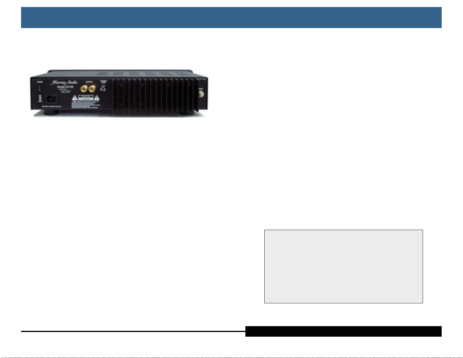
Rear Panel Features
Rear Panel Features
four
The rear panel was designed for flexibility and ease of access to
less frequently used functions. The high precision RCA input jack
and output connectors are heavily gold plated to minimize signal
degrading corrosion.
Power Connection
An IEC power cord connector is
provided for attaching the Herron
Audio-provided power cord or
another chosen by the user.
Power Switch
When placed in the on position,
the unit is powered up. At power
up, the unit goes through a start-
up sequence and remains muted
until the output light comes on.
When the switch is moved to the
off position the unit is automati-
cally muted and powered down.
Output Terminals
The M150 has two gold-plated
Tiff speaker binding post termi-
nals. These terminals are labeled
with the designation “OUTPUTS”
on the rear panel of the unit.
The polarity is designated with
red and black insulating collars.
The red collar signifies the posi-
tive terminal. The M150 is non
inverting. Connection to the
speaker binding post terminals
should only be made while the
unit is powered down.
Owner’s Manual
Please read the Owner’s Manual completely BEFORE operating the unit.
five
Speaker Fuse
The speaker fuse holder is pro-
vided in order for the user to
select the proper protection for
the speaker system to be used
with the M150. The M150 is capa-
ble of producing 150 watts at 8
ohms and 275 watts at 4 ohms.
If the proper value for this fuse
is not known, consult the speaker
manufacturer. An AGC 6 amp
fuse is provided from the factory
with the M150.
Heat Sink
The heat sink on the back panel
of the M150 is designed to dissi-
pate heat generated by the output
section of the amplifier. For best
performance and long life the
unit should be used in a well
ventilated area. Excessive heating
may occur under heavy load
conditions in a poorly ventilated
location and could cause the
unit to shut down.
Input Connector
The M150 has one gold-plated
Tiff RCA input connector. The
RCA input plugs (interconnect
terminations) should be inserted
firmly into the input jack while
the unit is powered down. It is
not recommended that the unit
be powered on without an input
connection.
Connection to the speaker binding post terminals
should only be made while the unit is powered down.
The RCA input plugs (interconnect terminations) should
be inserted firmly into the input jack while the unit is
powered down. It is not recommended that the unit be
powered on without an input connection.

Owner’s Manual
Please read the Owner’s Manual completely BEFORE operating the unit.
Herron Audio M150 Power Amplifier
Troubleshooting
Troubleshooting
seven
Symptom
1. The output light is on (green) and there is no sound.
A. Check the speaker fuse on the back of the unit.
B. Check speaker terminations
C. Check the interconnect terminations at the M150 and
at the preamplifier.
D. Check the source equipment.
2. The power light is on, but the voltage light goes on and off
and the output light does not come on. No Sound.
A. Check input source for d.c. at its output. Note: It is not
uncommon for preamplifiers and other audio source
equipment to produce a d.c. offset for a short period of
time after being powered up. This condition will nor-
mally clear up after a few minutes. It is recommended
that the M150s be powered up after the preamplifier,
phono stage, CD player, etc. have been turned on.
3. The amplifier trips off while the output light and voltage
light periodically go out (the sound is interrupted) when
listening at high volume.
A. This condition occurs when the internal protection cir-
cuits detect an over-current condition. This is only
likely to occur if the unit is driven into clipping or if
the speaker load is less than 4 ohms.
six
Placement
Although the M150 power ampli-
fier runs relatively cool, it is
recommended that these ampli-
fiers are used in an open area for
best operation and prolonged life.
Each M150 contains an over-
sized toroid transformer wound in
a configuration designed for mini-
mum magnetic field radiation. It is
recommended, however, that the
M150s be placed at least a few feet
away from sensitive front end
equipment such as a turntable or
phono stage.
Power Connection
When possible, connect the same
power outlet used for the preamp,
phono stage, CD player, etc. This
configuration will minimize the
reactive currents from power line
RF that will be impinged on the
interconnect cables between the
audio equipment in the system.
Recommended Loading
We do not recommend using the
M150 with a 2 ohm load. As with
all audio amplifiers increasing the
load will increase the distortion
and defeat the purpose of having
a really clean amplifier such as the
M150. For this reason we did not
design the M150 to drive a 2 ohm
load to full power. The over-cur-
rent trip circuits will engage under
those operating conditions.
Speaker Fuse
The M150 is supplied with an
AGC 6 amp speaker fuse from the
factory. The user may wish to
install an AGC fuse with a lower
rating depending on the type of
speakers being used. Careful selec-
tion of the appropriate fuse is
recommended since the M150 is
capable of supplying power well
beyond the ratings of many
speaker systems.
Speaker Cable
Optimum performance from the
M150 will be obtained only with
careful selection of the appropri-
ate cables from the amplifier to
the speakers. Minimum capaci-
tance and inductance is preferred
in order to avoid over-shoot and
ringing in the cables. Here, simple
high quality cable is of utmost
importance.
Installation
Installation

Owner’s Manual
Please read the Owner’s Manual completely BEFORE operating the unit.
Herron Audio M150 Power Amplifier
M150 Technical Specifications
M150 Technical Specifications
nine
Configuration Single-channel (monaural)
Frequency response 20 to 20kHz +/-0.1dB
Output Power 150 Watts @ 8 ohms, 275 Watts @ 4 ohms
(measurements at 1 kHz)
Gain 24 dB
Input Impedance 220k Ohms
Speaker Fuse AGC 6 amp supplied, value to be selected by
user for proper speaker protection.
Absolute Polarity Non-inverting
Power Requirements 100, 120, 230, 240 VAC. 50/60 Hz.
Standard IEC power connector
Toroidal transformer taps internally selected
for appropriate voltage
Main(s) Fuse 120 VAC - MDL5, 100 VAC - MDL4, 230 VAC
- MDL3, 240VAC - MDL-3
Dimensions 19” wide ×4” high ×10.5” deep
Warranty 5 years, parts and labor
Manufactured by Herron Audio Division of Herron Engineering, Inc.
St. Louis, Missouri
Troubleshooting—cont’d
Troubleshooting—cont’d
eight
4. The amplifier trips off and the output light turns red (the
voltage light goes off). This condition indicates that the
output section of the amplifier has over-heated (78 degrees
centigrade). Make sure that the unit is adequately venti-
lated. The unit will turn back on automatically when the
heat sink has cooled to 68 degrees centigrade.
5. The power light comes on but the voltage light never
comes on.
A. The M150 contains two AGC 6 amp internal rail fuses
(F2 and F3) located on the p.c. board for circuit protec-
tion. In the unlikely event of a failure of one or both of
these fuses, red indicator lights will be visible through
the vents in the top of the unit.
Table of contents
Other Herron Audio Amplifier manuals

Herron Audio
Herron Audio M1 User manual

Herron Audio
Herron Audio VTPH-1 User manual

Herron Audio
Herron Audio VTSP-3 User manual

Herron Audio
Herron Audio VTSP-3A User manual

Herron Audio
Herron Audio VTSP-2 User manual

Herron Audio
Herron Audio VTPH-2 User manual

Herron Audio
Herron Audio VTPH-2 User manual

Herron Audio
Herron Audio VTSP-3A User manual

Herron Audio
Herron Audio HL-1 User manual

Herron Audio
Herron Audio VTSP-1A/166 User manual


