audiophony BM-SCAN User manual

USER GUIDE
H10878 - Version 1 / 03-2018
Magnetic field strenght meter
BM-SCAN

BM-SCAN - Magnetic field strenght meter
Page 10
English
1 - Role of the measurer
2 - Measurer Operation
The field measurer has been designed to ensure that magnetic loop systems are installed and
certified according to the new IEC 60118-4 standard. When these standards are respected,
the comfort of the user will be identical wherever he is using his prosthesis equipped with the
T position.
The BM-SCAN makes it possible to commission an installation and certify its conformity.
To do so, please follow the procedure for receiving the magnetic loops in the appendix.
You can then complete the certificate of compliance.
ON - Press and hold button A until the display lights up
Off - Press and hold button A until the unit turns off
When the process is finished the screen turns black
1 - In modes 1 - 3 press button "B" to reset the measurements
2 - In mode 4, press button "B" to advance the frequency by third octaves
When you press the "A" key, it first displays the "BackGround Noise" mode, you must press the
button again to switch to the next mode:
1 - "BackGround Noise" magnetic pollution test
2 - "RMS / Peak" signal measurement
3 - "Field Strength" magnetic field measurement
4 - "Third Octave" Level Measurement
2-1 Switching the field measurer on/off
2-2 Mode selection
2-3 Button "B" function

AUDIOPHONY PUBLIC ADDRESS
Page 11
English
4 - "Background" magnetic pollution level test
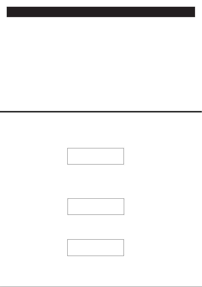
When the measurer is switched on, the "Weighted" background noise mode appears. The
display will show the RMS value on the first line and the MAX value on the second line. Press
button "B" to reset the MAX measurement.
Location of the receiver coil
"A" button M/A and control mode button
Menu / operation button
Control button "B"
Reset/Select
3 - Componants
Background noise
Weighted mode
A-RMS : -42.5 dBA
MAX : -37.9
4-1 Activating the pollution level test mode

BM-SCAN - Magnetic field strenght meter
Page 12
English
5 - RMS/Peak signal level
When testing the background noise of a new building, turn on all lights, fans, sound
system and other electrical equipment as if the building were in use. If you certify an
installation, this test is performed without the hearing loop system being activated.
Walk in all areas where the loop system will be used, holding the meter upright at listening height.
The important reading will be MAX reading. However, it is important to look at the RMS reading.
If the MAX reading exceeds -32dBA (measurements above -32dBA will have a lower negative
number, for example -30dBA means there is more background noise than -35dBA), you will
need to specify areas where these noise levels are higher.
Notes and requirements of Standard 60118-4
The standard revised in 2004 notes that any background noise level below -47dBA will result
in excellent signal / noise, but levels below -32dBA are acceptable and meet the requirements
of the standard. If the background noise level is greater than -32dBA, building managers
should be informed so that the source of the interference found can be repaired or isolated.
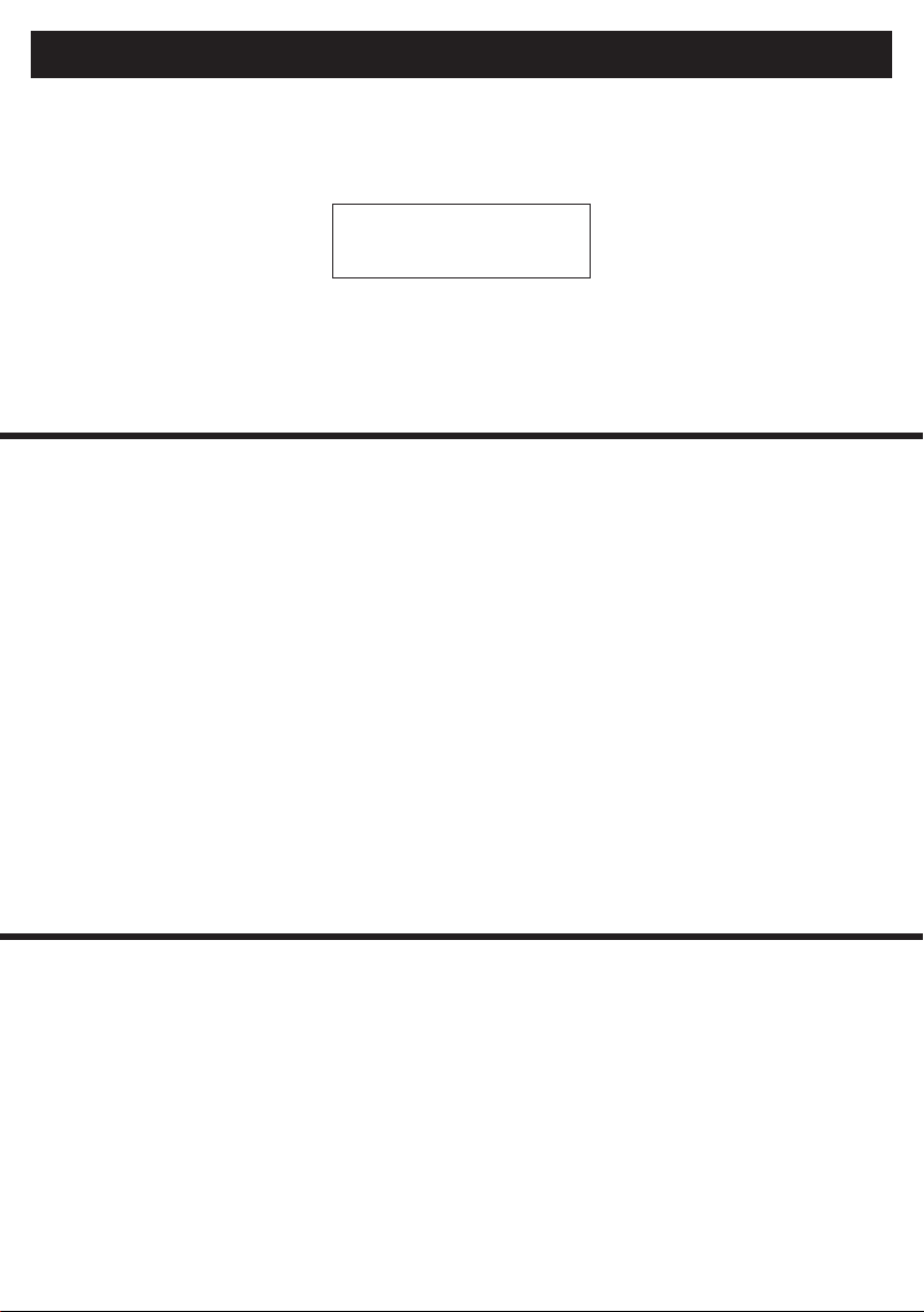
The second mode is used to configure the audio loop signal level using a weighting filter. It is
very difficult to set the field strength to an average of -12dBA as it will vary depending on the
program used to configure the system. We will use the PEAK reading to confirm that our design
and equipment meet the specifications of the standard. Press key "B" to reset PEAK playback.
Once the loop system has been installed, create a limited pink noise (100Hz to 5KHz) of the loop
system bandwidth. Walk around the hearing area holding your meter vertically.
RMS / Peak
Weighted mode
A-RMS : -12.5 dBA
MAX : -0.2
4-2 How to test background noise?
5-1 Principle
AUDIOPHONY PUBLIC ADDRESS
Page 13
English
Note the readings and confirm that the A-RMS level does not vary by more than ± 3dBA. This
lets you know that the signal level perceived in hearing aids will be the same no matter where
the person is.
Next: Using an audio program similar to what is normally used in the building, adjust the level of
the audio program to just above "normal". Now turn on the loop system and adjust the player
level until a -3dBA to 0dBA level is obtained in the center of the loop. Reset the PEAK level and
confirm that this level is on average 0 dB in the people's listening device.
Notes and requirements of Standard 60118-4
The standard states that the signal level in the loop area should not vary by more than ± 3dB.
Once confirmed, the signal level from the normal building program should peak at 0 dB as
referenced at 400mA/m. This confirms that there is adequate loop current to produce both
maximum and average signal levels (average is de-12dB or 100ma/m) for hearing instruments
equipped with the T position.
The methods below are two processes that can be used to confirm that the system correctly
reproduces all required frequencies equitably in the 100 to 5KHz bandwidth. A signal tester
generator such as the BM-SCAN will be required to perform these tests. Both methods will give
precise results.
Send the following sinusoidal signals through the loop system without adjusting any of the audio
level or loop controls: 100Hz, 250 Hz, 500 Hz, 1000 Hz, 2500 Hz and 5000 Hz.
Using the flat mode, record the RMS level generated by each of these. To meet the specification
of the standard the levels shall not vary by ± 3 dB.
Send a pink noise signal into the magnetic loop system and select the third octave mode on the
meter. It will initially start at a center frequency of 1000 Hz.
Press button "B" to scroll through the frequencies 100Hz, 200Hz, 500Hz, 1000Hz, 2500 Hz and
5000 Hz.
6 - Frequency response
Field strength
Flat reaction
Third octaves
F = 1000 Hz
6-1 Method I - Sinusoidal signal
6-2 Method II - Pink noise signal
FS-RMS : -12.5 dB
MAX : -10.2
BM-SCAN - Magnetic field strenght meter
Page 14
English
Notes and requirements of Standard 60118-4
The standard notes that in frequencies from 100Hz to 5000Hz the loop should also reproduce all
signals. At a minimum, systems should be tested at 100Hz, 1KHz and 5KHz.
Record RMS level readings for each frequency.
As in method I, if the level does not vary by more than ± 3dB, the installed system meets the
IEC specifications of the standard. This method was requested by the technicians so that they
could perform the test with an instrument without continuously adjusting the frequency source.
It also facilitates testing in several locations.
In the menu, the following items can be set: backlight level, headphone output type, headphone
volume, display units (dB, mG, uT) and switch-off delay (5 to 30min or none).
The 2-purpose headphone output jack: First, it can be used to monitor the loop program and
gives you a weighted output signal that can be heard with standard headphones. To change
the headphone volume, drag the Use / Menu button to Menu and use the Mode button to
switch to the headphone volume. By pressing the "select" button, you will be directed to the
volume control screen where the upper button increases the volume and the lower button
decreases the volume. Once set, simply return to operation to save the setting.
A complete spectrum output can be sent from this same connector which could then feed a
spectrum analyzer.
This would show the signal level at different frequencies and help confirm proper operation
and evaluate the frequency and level of any interference.
To switch from Weighted to Flat: With the display on, switch to Use / Menu in "Menu", press
the "A" mode button once to go to the Headphone Jack setup screen, then, by pressing the
"B" selection button, you can choose a weighted or flat spectrum.
7 - Headphone output
8 - Menu settings
BP-RMS : -22.5 dB
MAX : 1000 Hz

AUDIOPHONY PUBLIC ADDRESS
Page 15
English
9 - Ligne en mode réponse plate
10 - Specifications
There is a new feature which is the dBV audio level. The measurements and the display allow
to control the signal level coming from the sound system of the place. Poor sound in the loop
system often comes from a low signal level in the sound system. This input uses the latest mode
on the FSM and displays a specific level.
We recommend a level between -10dBV and 0dBV.
To use this feature scroll through the different modes until you see
"Line In Flat Response" on the screen.
Measuring range: -62dB to +9dB (0dB = 400mA/m)
Peak factor : <3
Resolution: < 0.1dB resolution for higher levels -32dB
Measurement resolution: 0.1 dB
Detection type: RMS on all features
Sensor : Coil sensor
Direction of sensitivity: In vertical position of the sensor (noted on the product)
Calibration : Calibrated at 1000 Hz (sine) read 0 dB at 5.03 mG
Frequency response: Flat ±1dB from 50 Hz to 10,000 Hz
Weighting: 2 meters specified in standard 61672-1
Power Source: Battery (9V) and external power outlet
Headphone jack: Weighted or flat output (selectable)
Display: 16x2 LCD
Backlight: blue LED (adjustable brightness)

BM-SCAN - Magnetic field strenght meter
Page 16
English
Standard EN 60118-4 of March 2007
This standard defines 4 very precise parameters.
The following procedure is recommended:
•The peak magnetic field must reach 400mA/m (integration time 0.125ms).
•Frequency responses should not vary more than 3dB between 100Hz and 5000Hz.
•The signal-to-noise ratio must be 47 dB (A-weighting).
•The magnetic field must be uniform throughout the listening area.
The type-approval procedure
•
•
•
Recommendation
Thanks to the law of February 2005, establishments receiving the public (ERP) are gradually equip-
ping themselves with magnetic induction loops in order to facilitate listening for people with hearing
difficulties. To be effective these systems must be carefully calibrated to verify that the installation
has been made in compliance with standard EN60118-4. We recommend the delivery of a certifi-
cate of conformity to this standard, according to the model enclosed, signed by the installer.
To allow a good listening it is necessary to check all these conditions.
The respect of the magnetic field intensity guarantees that the sound intensity is sufficient, the
responses frequency control ensure that the entire sound spectrum is perceived in the same way
and the signal-to-noise ratio measures the impact of interference magnetic disturbances on intelligi-
bility. Despite the installation of adequate equipment, many factors can disturb these parameters:
the presence of metallic structures causes the magnetic field to drop, transformers or current at
50Hz in the proximity cause magnetic noises. The size and the form of the room can make it difficult
to meet the recommended values at all points.
Procedure for receiving
magnetic loops
Room managers must ensure that, when installing any magnetic induction loop, the installer delivers
this certificate of conformity. Even if the room manager does not have the competence to judge the
result of the measurements, this "installation report" should be able to be consulted at any time for a
possible control by a team of auditors.
About the room, determine the points where the measurements will be taken ( center, extremities,
points near metal structures or noise sources).
Measurements by the installer, after the adjustment of the installed equipment, of the various
parameters set by the standard.
Delivery of this document signed by the installer to the room manager.

AUDIOPHONY PUBLIC ADDRESS
Page 17
English
Certificate of conformity
to IEC 60118-4 standard
Definition of the listening area for the hearing impaired
Standard: 1m to 1.4m
Standard: 1m to 2m
Area of use
1
Sketch of the room and listening area (indicate scale and dimensions)
search for listening areas
with background noise
Zones > -22dB
Zones > -32dB
Background noise
2
Customer: ...........................................Installer: .................................. Équipement : .................................
Location:.........................................Room: ..................................................Serial N°: .................................
Comments: ........................................................................................................................................................
.............................................................................................................................................................................
I declare that the installation
complies with the IEC 60118-4 standard
Installer's signature :Date : //
7
Existence of other
systems nearby
Yes
No
Interferences
Testing with end users
6
Magnetic field intensity
after adjustment
3
A B C D E F G H I J K
Measurement points
Height (in meters) =
Indicate 4 to 6 points (A to F) inside the room to perform the measurements – centre, corners, sides, front back, etc.
Frequency response
after adjustments
Magnetic field measurement
after adjustments
5
100Hz
1kHz
5kHz
4

Because AUDIOPHONY®takes the utmost care in its products to make sure you only get the best possible quality, our products are
subjects to modifications without prior notice. That is why technical specifications and the products physical configuration might differ
from the illustrations.
Make sure you get the latest news and updates about the AUDIOPHONY®products on www.audiophony.com
AUDIOPHONY®is a trademark of HITMUSIC SAS - Parc d'activités Cahors sud - 46230 FONTANES - FRANCE
Table of contents
Other audiophony Measuring Instrument manuals


