Phoenix Mecano Zero-flux TOPACC-HC User manual

User Manual TOPACC-HC
ZF 02.095EN rev.D
Page 1 of 19
Zero-flux™ Current Measuring System
PM Special Measuring Systems B.V.
Euregioweg 330B
7532SN Enschede
The Netherlands
Phone
E-Mail
Internet
: +31 537 400 740
: info@pm-sms.com
: www.pm-sms.com
User Manual
TOPACC-HC

User Manual TOPACC-HC
ZF 02.095EN rev.D
Page 2 of 19
Document number: ZF 02.095EN
Revision / Date : D / December 2010
PM Special Measuring Systems B.V. operates a policy of continuous development and improvement. PM
Special Measuring Systems B.V. reserves the right to change the contents of this manual without prior
notice.
Reproduction in any form, in whole or in part is not permitted without written consent of PM Special
Measuring Systems B.V.
Please stick rating plate here.

User Manual TOPACC-HC
ZF 02.095EN rev.D
Page 3 of 19
1. INTRODUCTION ______________________________________ Fout! Bladwijzer niet gedefinieerd.
1.1 The basic principle ________________________________ Fout! Bladwijzer niet gedefinieerd.
1.2 The burden resistor________________________________ Fout! Bladwijzer niet gedefinieerd.
1.3 The precision amplifier _____________________________ Fout! Bladwijzer niet gedefinieerd.
2. TECHNICAL SPECIFICATIONS____________________________ Fout! Bladwijzer niet gedefinieerd.
3. AVAILABLE STACC-HC SYSTEMS __________________________ Fout! Bladwijzer niet gedefinieerd.
3.1 Types __________________________________________ Fout! Bladwijzer niet gedefinieerd.
3.2 Version _________________________________________ Fout! Bladwijzer niet gedefinieerd.
3.3 Applied Measuring Heads ___________________________ Fout! Bladwijzer niet gedefinieerd.
4. INSTALLATION _______________________________________ Fout! Bladwijzer niet gedefinieerd.
4.1 Mounting _______________________________________ Fout! Bladwijzer niet gedefinieerd.
4.1.1 Electronics Module _________________________________ Fout! Bladwijzer niet gedefinieerd.
4.1.2 The Measuring Head _______________________________ Fout! Bladwijzer niet gedefinieerd.
4.2 Electrical connections ______________________________ Fout! Bladwijzer niet gedefinieerd.
4.2.1 Electronics Module _________________________________ Fout! Bladwijzer niet gedefinieerd.
4.2.2 The interconnection cable ___________________________ Fout! Bladwijzer niet gedefinieerd.
4.2.3 The Measuring Head _______________________________ Fout! Bladwijzer niet gedefinieerd.
5. INDICATIONS ________________________________________ Fout! Bladwijzer niet gedefinieerd.
5.1 Power on LED ____________________________________ Fout! Bladwijzer niet gedefinieerd.
5.2 Output valid LED__________________________________ Fout! Bladwijzer niet gedefinieerd.
5.3 Zero current LED__________________________________ Fout! Bladwijzer niet gedefinieerd.
5.4 Potential free contacts _____________________________ Fout! Bladwijzer niet gedefinieerd.
6. COMPOSITION OF THE STACC-HC ________________________ Fout! Bladwijzer niet gedefinieerd.
6.1 The Measuring Head _______________________________ Fout! Bladwijzer niet gedefinieerd.
Standard_________________________________________________ Fout! Bladwijzer niet gedefinieerd.
With calibration windings____________________________________ Fout! Bladwijzer niet gedefinieerd.
With 1 tap _______________________________________________ Fout! Bladwijzer niet gedefinieerd.
6.2 Electronics module ________________________________ Fout! Bladwijzer niet gedefinieerd.
6.2.1 The power supply module ___________________________ Fout! Bladwijzer niet gedefinieerd.
6.2.2 The power amplifier module _________________________ Fout! Bladwijzer niet gedefinieerd.
6.2.3 The burden resistor ________________________________ Fout! Bladwijzer niet gedefinieerd.
6.2.4 The controlloop ___________________________________ Fout! Bladwijzer niet gedefinieerd.
6.2.5 The precision amplifier______________________________ Fout! Bladwijzer niet gedefinieerd.
7. MAINTENANCE _______________________________________ Fout! Bladwijzer niet gedefinieerd.
7.1 Periodical maintenance_____________________________ Fout! Bladwijzer niet gedefinieerd.
7.2 Trouble shooting__________________________________ Fout! Bladwijzer niet gedefinieerd.
7.3 Tests ___________________________________________ Fout! Bladwijzer niet gedefinieerd.
7.3.1 Power supply _____________________________________ Fout! Bladwijzer niet gedefinieerd.
7.3.2 Power amplifier ___________________________________ Fout! Bladwijzer niet gedefinieerd.
7.3.3 Test signals on X2 _________________________________ Fout! Bladwijzer niet gedefinieerd.
7.3.4 Controlloop _______________________________________ Fout! Bladwijzer niet gedefinieerd.
a. Voltage stabilisers ____________________________________________Fout! Bladwijzer niet gedefinieerd.
b. Zero current detector__________________________________________Fout! Bladwijzer niet gedefinieerd.
c. Oscillator and induced voltage ___________________________________Fout! Bladwijzer niet gedefinieerd.

User Manual TOPACC-HC
ZF 02.095EN rev.D
Page 4 of 19
d. Peak detector________________________________________________Fout! Bladwijzer niet gedefinieerd.
e. Excitation control _____________________________________________Fout! Bladwijzer niet gedefinieerd.
f. AC-Loop ____________________________________________________Fout! Bladwijzer niet gedefinieerd.
7.4 Accuracy check ___________________________________ Fout! Bladwijzer niet gedefinieerd.
7.4.1 With standard resistor ______________________________ Fout! Bladwijzer niet gedefinieerd.
7.4.2 With reference DCCT _______________________________ Fout! Bladwijzer niet gedefinieerd.
7.5 Calibration ______________________________________ Fout! Bladwijzer niet gedefinieerd.
7.5.1 Procedure for adjusting offset ________________________ Fout! Bladwijzer niet gedefinieerd.
7.5.2 Procedure for gain and CMR _________________________ Fout! Bladwijzer niet gedefinieerd.
8DRAWING NUMBERS __________________________________ Fout! Bladwijzer niet gedefinieerd.
9NOTES______________________________________________ Fout! Bladwijzer niet gedefinieerd.

User Manual TOPACC-HC
ZF 02.095EN rev.D
Page 5 of 19
1. INTRODUCTION
The bipolar Zero-fluxcurrent transformer System TOPACC-HC, developed by PM SMS for scientific
research, epitomise the concept of a
galvanic ally separated system for
measurement of direct and
alternating high currents up to 30 kA
with exceptionally high accuracy and
stability.
1.1 The basic principle
The principle of measurement is
based on obtaining a perfect balance
between the magnetic flux generated
by the current in the primary current
carrier and that generated by the
current in the secondary winding
situated in the measuring head. This
balance is known as the condition of
zero flux.
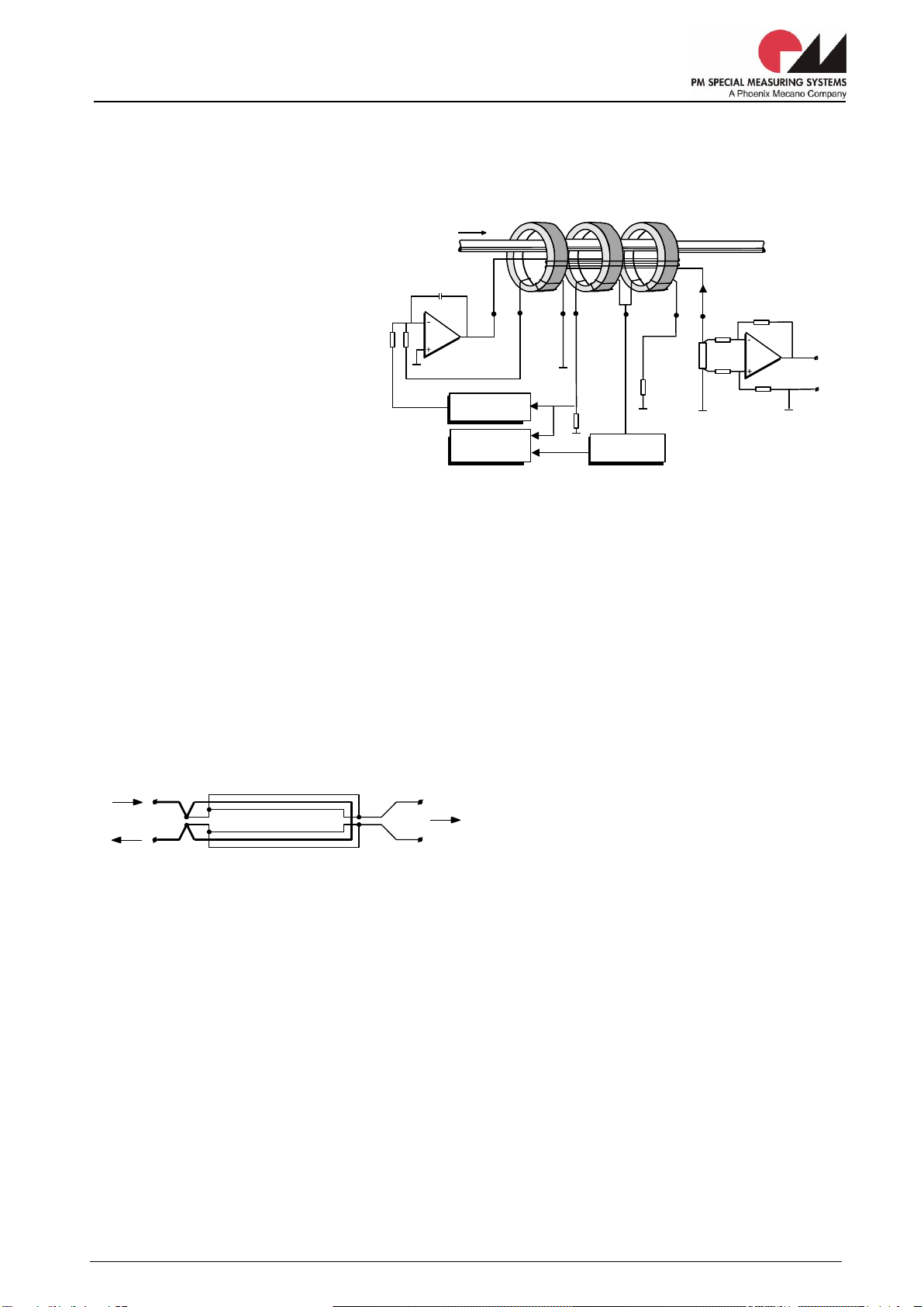
The current to be measured is sensed by a toroidal ring core which is mounted around the primary
conductor. A magnetic field is generated by the primary current Ip. The electronics module of the
TOPACC-HC produces a current in the secondary winding of the core in the measuring head, which
creates a counteracting magnetic field. When the magnetic fields balance each other this is known as the
condition of zero-flux. The TOPACC-HC has a magnetic modulator with a patented peak detector. It
continuously checks whether the secondary ampere-turns are in perfect balance with the primary. The
secondary current, which is an exact image of the primary current, is fed trough an external burden
resistor to make the signal available for further use. The TOPACC-HC’s unique design provides high
accuracy and stability without the need for special temperature control devices.
1.2 The burden resistor
Extremely high requirements hold for the burden resistor into which the secondary current is fed. After
amplification in the output circuit of the TOPACC-HC Zero-fluxcurrent transformer the voltage across
this resistor must be suitable to allow very
accurate readings to be made, whether they are
ultimately produced in analogue or digital form. In
view of the required measurement precision a
four-wire resistor is the best. Despite the fact that
high-quality resistors can be purchased on the
industrial market, for technical reasons, PM SMS
much prefers to make its own for the TOPACC-HC.
A special coating contributes to the long-term stability. To achieve a high bandwidth the current and
voltage conductors are put close together in a special way. These measures enable a bandwidth of 1 MHz
to be achieved. To reduce any thermocouple effects which might arise between the alloy of the resis-
tance wire and the copper of the voltage conductors good thermal coupling is made between the two
voltage pick-offs. The thermal stability of the burden resistor under nominal load conditions is, even over
the long term, ensured without the need of resorting to heating elements, Peltier elements or constant
temperature chambers.
1.3 The precision amplifier
The precision amplifier is a very stable differential amplifier, which delivers a highly accurate output
voltage of 10V when the secondary current through the burden resistor meets the rated value. To ensure
that the amplification factor remains constant, the most important point is that the temperature
coefficients of the four amplifier resistors are matched (TCR tracking). The offset error is minimised by
careful choice of the operational amplifier. The precision amplifier is fitted with sensing outputs to
compensate for voltage losses in the externally connected conductors upgrading the measurement
precision of the TOPACC-HC Zero-fluxcurrent transformer. Furthermore, sensitivity to HF interference is
much reduced by capacitive coupling of these outputs.
Ip
Ns
Oscillator
Saturation
detector
Power
Amplifier
Burden
Resistor
Output
Is
Precision Amplifier
Peak detector
N3
N2
N1
7
5
6
3
4
1
2
8
Fig.1 Basic diagram of the Zero-fluxcurrent transformer
To precision amplifier
V
Is
Fig.2 Construction of burden resistor

User Manual TOPACC-HC
ZF 02.095EN rev.D
Page 6 of 19
2. TECHNICAL SPECIFICATIONS
PRIMARY CIRCUIT
Rated current
up to 30 kA
Permissible overcurrent
1.1 Irated (1)
Short-circuit current
10 Irated (0.1s)
Current slew rate
unlimited
OUTPUT CIRCUIT
Rated voltage
10 V
Maximum load current
5 mA
Output impedance
< 10 m
Output slew rate (10-90%)
> 1.5 V/s
Small signal bandwidth (<5% of rated primary current)
0...100 kHz
Noise (rms) * 0 - 10 Hz
< 0.1 ppm
related to rated * 0 - 100 Hz
< 0.3 ppm
output voltage * 0 - 10 kHz
< 1.5 ppm
DC ACCURACY
Offset error * initial (at 25C)
< 2.5 ppm
related to rated * vs. temperature
< 0.5 ppm/K
output voltage * vs. time
< 5 ppm/year
Ratio error * initial (at 25C)
< 25 ppm (2)
related to actual * vs. temperature
< 1 ppm/K
output voltage * vs. time
< 5 ppm/year
Linearity error related to actual output voltage
< 2.5 ppm
SIGNALLING
LED’s + relay contacts
Output valid
up to 1.1 Irated
Zero-current detection
at 0.01% of Irated
GENERAL DATA
Ambient temperature range
- electronics
10 .. 40 °C
- measuring head
0 .. 50 °C
Notes
(1) Up to the rated primary current a perfect ampere-turns balance is maintained. At some value above the specified
overcurrent level the cores become saturated, which will result in a non-defined output voltage. The output valid relay will
indicate this status. Proper operation will be restored as soon as the primary current has returned to I rated. The zero-current
relay will act when the primary current is below the specified detection level.
(2) By using specially selected and perfectly matching components it is possible to offer, as an option, a System TOPACC-HC
with a ratio error of less than 0.5 ppm/K.

User Manual TOPACC-HC
ZF 02.095EN rev.D
Page 7 of 19
3. AVAILABLE TOPACC-HC SYSTEMS
A standard bipolar TOPACC-HC Zero-fluxcurrent measuring system consists of:
Electronics Module (EM)
Measuring Head (MH)
Interconnection cable (standard length 3 m).
3.1 Types
Type
Maximal current
Performance
Model measuring head
THC10
6 . . . 10 kA
Bipolar
332-5
THC20
10 . . . 20 kA
Bipolar
332-5
THC30
20 . . . 30 kA
Bipolar
470-10
3.2 Version
Chassis for 19” rack
mounting
Dimensions:
Supply voltages:
Power consumption:
133 x 448 x 500 mm (3U, 19”)
400 Vac - 3 phase –50…60Hz
Other voltages on demand
300 VA
3.3 Applied Measuring Heads
Model
Dimensions
(mm)
Bore
(mm)
Weight
(kg)
Test Voltage
(kV-50Hz,1 min)
332-5
460 x 460 x
190
150
90
5
470-
10
600 x 600 x
220
250
110
5
The measuring heads can optionally be delivered with:
Calibration windings
1 tap
The drawings for the optionally measuring heads are also added to this manual.
The drawing numbers are described in chapter 8.

User Manual TOPACC-HC
ZF 02.095EN rev.D
Page 8 of 19
4. INSTALLATION
Both electronics module as measuring head have a unique rating plate for easy identification. As
electronics module and measuring head together form a measuring system the serial numbers on both
components are the same but have an additional code. This is the letter code EM for the electronics
module, and the letter code MH for the measuring head.
Do not expose the electronics module and measuring head to heavy shocks or rough handling. Keep
them in the original packing as long as possible.
Place the TOPACC-HC in a dry, and dust-free place with good ventilation. Air inlets and outlets must not
be blocked by anything. Heat accumulation inside the electronics module will reduce the accuracy.
Sources of heat below the electronics module should also be avoided for the same reason.
Relative humidity should be kept within 80% (10…40°C) for the electronics module. Condensation
moisture should be avoided as it can strongly degrade the specifications.
WARNING! Incorrect supply voltage will damage the electronics. Check if the indicated
supply
voltage on the electronics module corresponds to your power supply voltage.
4.1 Mounting
4.1.1 Electronics Module
The electronics is housed in a chassis for 19-inch rack mounting. The chassis is 3U high and is an EMC
type. The depth of the chassis is 500 mm, excluding the handles at the front and the connectors at the
rear side. The top and bottom covers (without vent slots) are easy removable for a good access to the
electronics. See drawing Dimensions of Electronics Module.
There are no special demands for mounting the chassis. It can be used as freestanding desktop system
or can be mounted in a cabinet. It is advisable to support the chassis with L-brackets when mounted in a
cabinet.
4.1.2 The Measuring Head
The measuring head is mounted between 2 insulating plates. Max. dimensions 460 x 460 x 220 mm. Hole
diameter 150 mm. The head has 4 lifting eyebolts for hoisting. See drawing Dimensions of Measuring
Head. The measuring head can be used in vertical or horizontal position.
Distance (E) for return busbar(s)
indicated from the outside of the head as
a function of the primary DC-current (Ip)
resulting into an error of max. 15ppm:
Note: Ip (DC-current) in kA, E in mm
With one return busbar:
E = 25 Ip
With two return busbars (symmetrical):
E = 10 Ip
With four return busbars (symmetrical):
E = 5 Ip
90°-bends in the central busbar must be at
a distance of twice found with above formulas.
External magnetic DC-fields of any origin and
orientation will produce an error of max. 1.5ppm/mT.
Saturation will occur somewhat above 10mT.
In other words above H = 8000A/m.
Radial displacement sensitivity of the central busbar: Error max. 2ppm/cm at rated primary current.
static screen
secondary winding
magnetic screen
primary busbar
auxiliary winding
core
Fig.3 Cross-section of the measuring head
E
busbar for returning current
Ip

User Manual TOPACC-HC
ZF 02.095EN rev.D
Page 9 of 19
4.2 Electrical connections
Electronics Module see drawing: External Connections of Electronics Module
Measuring Head and connection cable see drawing: Wiring diagram of Measuring Head and cable
4.2.1 Electronics Module
a. Mains supply connector X1
The standard supply voltage is 400V - 3 phase –50…60Hz. Other voltages on demand. For connecting
the electronics module to the mains supply a 7-pole Burndy connector is supplied. Please refer to the
mains rating plate on the rear of the module for the correct voltage.
WARNING! Incorrect supply voltage will damage the electronics. Check if the indicated
supply voltage on the electronics module corresponds to your power supply
voltage.
The power supply is protected at the primary side with a circuit breaker with thermal action. This circuit
breaker is a push button activated, 2-pole sensing, 3-pole switching device.
For personal protection, earthing the system is advisable. If the mains supply is not provided with an
earth lead, as in some countries, use the fast-on connection on the rear of the module to earth it
separately. Follow the instructions from the local power company for safeguarding against electrical
shocks.
b. Status signals connector X2
At this 12-pole Burndy connector, the contacts of 3 status-relays are available. They signal the status
"output valid" "zero current" and “circuit breaker on”. To ensure a maximum EMI-screening connect the
metal connector hood with the screen off a multi-core cable. In this way the cable-screen is connected
with the chassis via the metal connector housings. Furthermore two test signals - via series-resistor 10K
- and a common are provided. See also drawing External Connections of Electronics Module.
WARNING! Do not use the test signals at pins 8, 9 and 10 at normal working conditions. This
could affect the accuracy.
c. Measuring head connector X3
The measuring head cable is connected to electronics module with a 19-pole Burndy connector.
d. Output signal connector X4
The output signal is available at the 4-pole connector. System TOPACC-HC is equipped with a 4-wire
voltage output for High, Low and two sense connections.
To improve the Electro Magnetic Compatibility (EMC) it is advised to use a cable with two twisted pairs of
conductors and a braided or foil screen. One end of the cable screen is connected to the shell of the
counterpart of X4, which is supplied with the electronics module. The other end of the cable screen
should be connected in a similar way. The screen must be connected directly to the chassis at the user
side. Preferably use one twisted pair for High and Low and the other pair for the sense connections.
1. The 4-wire connection is given in fig.4
It has the advantage of compensating the voltage losses in the wires due to a load current (max. 5mA).
However, it also increases the gain a little bit by adding some resistance to the feedback resistor (10 or
20k) in the Hsense line.
Example:
A cable of 2.5m with wires AWG24 (0.2mm2) results into a ratio error of +10ppm.
At the Low side the sense connection automatically compensates for CM voltages that could exist between common
at TOPACC-side and common at user-side. The sense connection in the Low side does not influence gain.

User Manual TOPACC-HC
ZF 02.095EN rev.D
Page 10 of 19
2. Also a 3-wire connection is possible.
It has the advantage that gain (ratio error) is not influenced by cable resistance and various lengths.
It can be used if the input at the user-side is high impedant. High and Hsense can be shorted at the cable
part of X4. Alternatively a wire can be soldered across d24 and z24 of the chassis connector for the
precision amplifier. However, voltage loss due to a load current will not be compensated.
Example: A cable of 2.5m with two wires in parallel of AWG24 (2x0.2mm2) will result into a ratio error of
-50ppm if the impedance at the user-side is 2k.
It is advised to use the Lsense connection as in fig.4 to compensate for CM voltages (see also 1).
Note:
Common of the electronics (indicated with "o” or "" in fig.4) and the chassis are galvanically isolated but H.F.-
coupled with a 0.68F/ 630V capacitor. This capacitor is located inside the power supply module of the TOPACC-HC.
4.2.2 The interconnection cable
The interconnection cable from electronics module to the measuring head has a standard length of 3
meters. A special 6-pair halogen free cable with an overall foil screen is used for maximum shielding. The
core cross section is 1.3 mm2. Without special modifications it can be extended up to 15 meters. Above
this length another cable diameter has to be applied to compensate for the voltage drop. The
interconnection cable is equipped with male and female 19-pole connectors.
4.2.3 The Measuring Head
Two or three connectors are mounted on the head; a 19-pole type for the connections to the electronics
module and one or two 4-pole types for other purposes.
MH standard
connector X1 : for cable to Electronics Module
connector X2 : connected with secondary windings (for normal operation X2 must be
terminated with the shorting plug as delivered)
Note: for test purposes a specially wired connector can be applied onto X2.
This will turn Ns2 into a test winding. Ns1 will remain as a secondary winding.
MH with calibration windings
connector X1 : for cable to Electronics Module
connector X2 : for calibration windings (shorting plug not applicable)
Note: duty rating of calibration winding is 1/2 h per 12h.
MH with 1 tap
connector X1 : for cable to Electronics Module
connector X2 : full secondary windings (high range) to be selected with the shorting plug
connector X3 : tap of secondary windings (low range) to be selected with the shorting plug
Note: for test purposes a specially wired connector can be applied onto X2 (X2 or X3) can be used.
This will turn Ns2 into a test winding. Ns1 will remain as a secondary winding.
TOPACC-HC
CABLE
X4
Is
-
+
Precision amplifier
twisted pair
Connector shell
H sense
High
L sense
Low
Cable screen
o
USER
3
1
4
2
DAC
i.e. summing ampl.
-
+
Chassis
Protective earth
Fig. 4 4-wire connection with dual pair screened cable

User Manual TOPACC-HC
ZF 02.095EN rev.D
Page 11 of 19
5. INDICATIONS
The System TOPACC-HC is equipped with several LED indicators for quick survey. They are located in the
frontpanel of the electronics module. All LED's indicate a "true" situation. Also indications are available on
potential free contacts for remote monitoring.
5.1 Power on LED
This LED indicates the presence of the DC voltage on the printed circuit boards. It has only a simple
series resistor so an under- or over voltage situation is not signaled. The color of the "power on" LED is
red.
5.2 Output valid LED
It can happen that the primary current reaches such a high level that the secondary current required to
maintain the ampere-turns balance cannot be produced by the power amplifier. The zero-flux condition
will be preserved for primary currents up to the specified overcurrent level. However, if overcurrents last
for too long, the toroids become saturated and the output voltage no longer bears any relation to the
primary current. A detection circuit is therefore provided which signals this operating condition via a relay
and a green LED indicator. At the same time a reset circuit is activated which enables the TOPACC-HC to
restart normal operation as soon as the overcurrent condition ends.
5.3 Zero current LED
The bipolar TOPACC-HC is supplied with a zero current detector, which is activated when the primary
current drops below the specified zero-current detection level. This condition is signalled via a green LED
indicator in the frontpanel.
5.4 Potential free contacts
The indications "output valid" and "zero-current" are also available on potential free contacts for remote
monitoring. Also available is a potential free contact for the status of the circuit breaker.
See drawing External connections of Electronics Module. The contact rating is 60V/0.5A (AC or DC).

User Manual TOPACC-HC
ZF 02.095EN rev.D
Page 12 of 19
6. COMPOSITION OF THE TOPACC-HC
Measuring Head
Sec. Wind.
2
1
8
Is
Controlloop
Loop finder
AC-Loop
Balance
Power Supply
Power Amplifier
Oscillator
Peak detector
Output
valid
Zero
Current
detector
Lo
Hi
at front
Offset
Ratio
CMR
Burden
Precision Amplifier
-10 x
Mains
4
3
6
7
5
Prim. Wind.
Ip
Excitation
Control
Fig.5 Block diagram of the Zero-fluxcurrent transformer system TOPACC-HC

User Manual TOPACC-HC
ZF 02.095EN rev.D
Page 13 of 19
6.1 The Measuring Head
Standard
The number of secondary turns, series connected, normally results into a nominal compensation current
of 5A. The temperature rise of the secondary winding will be 50K maximum, after 24 hours of nominal
current. The thermal time constant is approx. 4 hours.
With calibration windings
The head with calibration winding consists of two identical 5A windings with a total number of ampere-
turns equal to that of the secondary winding. It can be used for in-site calibration (duty rating ½ h per
12h)
With 1 tap
A head with one tap has two measuring ranges. Example: 20kA/10V or 8kA/10V. By moving the 4-pole
shorting plug on the head the range can be selected.
6.2 Electronics module
The front panel has three LED’s for signalling “power on”, “output valid” and “zero current”. There are
also two holes for ratio and offset adjustments. The air inlet for the forced cooling is also at the front
panel. After removal of the front panel the two printed circuit boards with the controlloop and the
precision amplifier are accessible. The air outlet, connectors and protective devices are located at the
rear panel.
The electronics module consists of following sub-modules:
1. The power supply module.
2. The power amplifier module.
3. The burden resistor.
4. The controlloop printed circuit board.
5. The precision amplifier printed circuit board.
6.2.1 The power supply module
The power supply module must be supplied from a three-phase 400 Vac, 50…60Hz mains without
neutral. To avoid undesired EMI a conventional power supply was applied instead of a switch-mode type.
Three toroidal mains transformers are connected in a delta configuration at the primary side. They are
protected with a circuit breaker with thermal action. This circuit breaker is a push button activated type,
with 2-pole sensing and a 3-pole switching device. The secondary winding of each transformer has its
own bridge rectifier. The centre taps of the secondary windings are connected, being the neutral of the
bipolar power supply. The output voltage is approx. +/- 40Vdc when unipolar loaded with 5A. Each
supply-half has two 47F/63V capacitors with a life expectancy, at 85ºC / 63V / rated Ir, of 19 000 hours.
That is under normal working conditions at 40ºC approx. 450 000 hours (50 years).
6.2.2 The power amplifier module
The main part of the power amplifier module is a heatsink 50 x 190 x 200 mm. The thermal resistance is
approximately 0.5K/W at natural convection conditions. On this heatsink two insulated power stages are
mounted. Each power stage has 5 power transistors (TO-3) and a freewheeling diode. The power
components are mounted on an aluminium L-profile. On the heatsink space is reserved for a bipolar
“power-zener”, also mounted on an L-profile. This power zener can be used to dissipate energy in case of
short circuit currents. A temperature switch is mounted on the heatsink which trips the circuit breaker of
the power supply in case of excessive temperature rise. At normal temperature the contact of the
temperature switch is open.
The heatsink is forced-air cooled by two fans with ball bearings, life expectance at 40ºC: 80 000 hours.
To increase the life expectance the supply voltage, which normally is 24V, is lowered. Also for this they
are placed in the “cold” ambient air stream. The fans are powered individually.
All power semiconductors, which are carrying the secondary current or having protective functions, are
concentrated on the power amplifier module. Power semiconductors are used for the following functions:
PNP power stage (P), NPN power stage (N), an optional bipolar zener diode power stage (Z),
freewheeling diodes and diodes for the Io-detection. The high current connections are made via 8
terminals, with connections for the power supply, the secondary winding and the burden, which are
placed on a printed circuit board. This printed circuit board is mounted on top of the power amplifier

User Manual TOPACC-HC
ZF 02.095EN rev.D
Page 14 of 19
module and contains several auxiliary circuits such as speed regulators for the fans, drivers for the power
stages and terminals interconnecting the controlloop. The +/- 40V line for the controlloop is protected
with thermistors for overload protection. Furthermore there are some optional auxiliary circuits in case an
unipolar DCCT or a bipolar (2-stage) extremely high current DCCT with a H-bridge power amplifier is
requested.
6.2.3 The burden resistor
The burden resistor is the well-known “PM SMS specially made” high stability resistor with an absolute
accuracy of 0.1% R=0.2Ω. The Temperature Coefficient (T.C.) is better than 1ppm/K. Because of a
unique method of construction the “Joule-effect” is kept very low. The burden resistor is mounted directly
behind the ventilation slots in the front panel to be cooled with ambient temperature air. Extra attention
is paid to hermetic sealing of the housing of the burden to avoid leakage of the insulation fluid.
6.2.4 The controlloop
The electronics of the controlloop is placed on a Eurocard size printed circuit board (100 x 160 mm). It is
identical to the controlloop used in other PM SMS Zero-fluxDCCT systems like TOPACC, STACC and
CURACC. For technical reasons, the controlloop printed circuit board is designed with both SMD as
conventional “through hole” components. Accuracy demanding circuits, like the peak-detector and the
AC-loop, are built with conventional “through hole” components. The same applies for relatively high
dissipating components.
The controlloop consists of following functional blocks:
* The peak detector
is similar to the one that is already used for many years in the Zero-flux
TOPACC system and formerly the 600SIP system. It is a double peak detector, which produces a very low
ripple at its output. The driver stage has a current limiting function for the power amplifier and is
adjustable with fill-in resistors. The “output valid” relay is energised when the entire controlloop is
working properly. In case of saturation, disconnected wires, defective components, etc. the “output valid”
relay and the LED at the frontpanel are not energised.
* The zero current detection
circuit is only energising the relay and frontpanel LED when the primary
current is within a specified window. The level of the window can be set with a fill-in resistor, which is
placed at the controlloop PCB. The zero current detection circuit is interlocked with output valid so if, as
an example, the measuring head is not connected the output valid relay is not energised, which means
that also the zero current relay shall not be energised.
* The voltage stabilisers
are built up with discrete components for a maximum input voltage of 70V.
These
stabilisers create an output voltage of +15V and –15V
and are feeding the electronics of both the
controlloop as precision amplifier.
6.2.5 The precision amplifier
To create an overall exchangeability with other Zero-fluxproduced by PM SMS, the precision amplifier is
basically identical to the one used for the lower-current TOPACC. The printed circuit board is Eurocard
(100x160mm) sized. For the TOPACC-HC the standard on-board burden is omitted and replaced by a
detached model. The multi-turn potentiometers for ratio and offset adjustment are in this execution
accessible via the front panel. The amplification value is 10 times. A metal cap prevents the amplifier for
EMI and air-turbulence, which could result in LF-noise.

User Manual TOPACC-HC
ZF 02.095EN rev.D
Page 15 of 19
7. MAINTENANCE
7.1 Periodical maintenance
The TOPACC-HC needs no specific periodical maintenance. Re-calibration is suggested every 5 years.
The accumulation of dust, dirt or moisture can however affect the correct operation of the TOPACC-HC.
Depending on the operating conditions this should be checked once a year. Cleaning should be done with
low pressure, clean dry air or with a soft brush.
7.2 Trouble shooting
Troubles sometimes can be located by means of a visual inspection. This may be accomplished by
observing the following symptoms:
a. Accumulation of dirt, dust or moisture. Remove this contamination with low-pressure, clean dry air
or with a soft brush.
b. Scorched or burned parts. Damages of this type are usually caused by other defective components.
Determine the cause of damage before replacing components.
7.3 Tests
7.3.1 Power supply
If the LED's are not signalling as expected or when the output signals are conflicting with the input
conditions start to check the power supply.
The DC-value of the power supply should be ± 40Vdc. If the circuit breaker is activated, try to find an
explanation for this event first. The circuit breaker was specially selected for protecting the toroidal mains
transformer. Check the mains cable, internal connections, bridge rectifier and temperature switch on the
power amplifier (normally open).
7.3.2 Power amplifier
If a strong heating up of the heatsink is noticed even at zero primary current, it is possible that there is a
short-circuit between the collectors of the power transistors and the heatsink support (=0V). To check
this perform an insulation test with 100Vdc between the L-profiles and the chassis. The insulation
resistance should be more than 10MΩ. If needed replace the insulation washer.
7.3.3 Test signals on X2
At connector X2 two test signals are available. At pin 8 the magnetising current can be measured. At pin
9 the induced voltage of the power amplifier can be observed. Note that these signals are measured
against “common” at pin 10. The observed signals give a good indication of the behaviour of the system.
Magnetising current 1V/div.
Level 1.5 …. 2.5 Vpeak
X2 pin 8
TB: 5ms/div.
Induced voltage 0.5 V/div.
X2 pin 9
Note: The induced voltage can have any shape but is synchronous
with the magnetising current
Fig. 6 Normal excitation

User Manual TOPACC-HC
ZF 02.095EN rev.D
Page 16 of 19
7.3.4 Controlloop
The following tests can only be performed with the use of an extender board, in order to have all
connector pins available for measuring purposes. (F-type connector with the rows d, b and z).
* Measure always with respect to common (d4, b4, z4).
* Oscilloscope input: DC.
* Use measuring equipment with an input impedance of at least 1M.
* If not stated otherwise the Controlloop, the precision amplifier and the measuring head are
interconnected and the primary current is 0 (zero).
a. Voltage stabilisers
The "voltage stabilisers" should produce +15 ±0.5V on d2 and –15 ±0.5V on d6. The unstabilised
voltages enters at b2 (Vp = +40V) and at z6 (Vn = –40V) located at the power supply module.
b. Zero current detector
The "zero current detector” can be tested by putting a small DC-current trough the measuring head.
Relay 2 will switch over at a primary current level as specified.
c. Oscillator and induced voltage
A square wave oscillator generates a frequency of 72 ± 2Hz, with a fixed amplitude of 8 ± 0.5V. This
square wave can be measured at d16. The frequency can be fine adjusted with potentiometer P1.
A triangular-shaped voltage is derived from the square wave and has the same frequency.
Measure this at point d14. By adjusting the amplitude of the triangular-shaped voltage with
potentiometer P2, the magnetising current must be set to 2 ± 0.5V peak value. Measure at point b14.
With potentiometer P3 the "induced voltage" must be adjusted to find its minimum peak-value. The
wave-shape depends on the measuring head that is connected and is unpredictable. However it should
be synchronous with the oscillator frequency. Measure at X2 pin 9 (status signals).
When the secondary and primary ampere-turns are not canceling out (cut wires, defective amplifier, etc.)
the magnetizing current will show a different shape. (See figure below). When disconnecting X2 terminal
7 of the power amplifier, it is possible that the magnetizing current restores to the shape in the above
figure.
Square wave 10V/div.
point d16
Oscillator output 5V/div.
point d14
Magnetising current 1V/div.
point b14
TB: 5ms/div.
Fig. 7 Normal excitation
Oscillator output 10V/div.
point d14
TB: 5ms/div.
Magnetising current 1V/div.
point b14
Fig. 8 Excitation due to saturation

User Manual TOPACC-HC
ZF 02.095EN rev.D
Page 17 of 19
d. Peak detector
The output signal of the "peak detector" is shown in the figure below. The output signal is measured in
closed-loop situation. The wave-shape depends a lot of the adjustment made for induced voltage with
potentiometer P3, but will be synchronous with the magnetizing current. Measure at point d12.
To check proper operation of the peak detector disconnect X2 terminal 7 of the power amplifier and
measure the output voltage at point d12 with a voltmeter at zero primary current. Requirement: 0 ±
0.2V. Then have a current flow of 100mA in the direction of the arrow trough the measuring head. Now
the output voltage at point d12 will change about +0.5V.
e. Excitation control
The "excitation control" produces, under normal conditions, an average output signal lower than -9V.
Measure this at point d8.
f. AC-Loop
The output signal of the "AC-Loop", under normal conditions (Ip=0), is within ± 0.1Vdc. Measure this at
point d10.
Magnetising current 1V/div.
point b14
TB: 5 ms/div.
Output peak detector 0.1V/div.
point d12
Fig.9 Peak detector signals
Magnetising current 1V/div.
point b14
Zero line for excitation control signal
Excitation control 5V/div.
point d8
note: In case of a saturated measuring head, the voltage at point
d8 will drop to about zero.
TB: 5ms/div.
Fig.10 Excitation control

User Manual TOPACC-HC
ZF 02.095EN rev.D
Page 18 of 19
7.4 Accuracy check
Due to the very good long-term stability of the TOPACC-HC it is not really necessary to check the
accuracy periodically. Under normal operating conditions the ratio drift and offset drift versus
temperature and time will stay within the original specifications. Nevertheless, if an accuracy check is
required, the following circuits could be used.
7.4.1 With standard resistor
The secondary winding of the measuring head is indicated with Ns. For the primary winding a multicore
cable could be used with connectors at both ends. When putting together these connectors all cores are
series connected. The turns made with this cable should be well divided around the measuring head. The
standard 4-wire resistor must have a proven value and temperature stability. Assuming the TOPACC-HC
has a rated current of 12000A, Np must have 120 turns when the standard resistor is 0.1Ω. The
maximum output voltage (Vout=Vref) depends on the maximum dissipation allowed for the standard
resistor. For lowest thermal voltages the connections from Vref and Vout to the DC Null-Voltmeter should
be made with copper wire.
To measure the offset error, open the primary circuit (Ip=0). To measure the total error produce a
current of 10A in the primary circuit. In the suggested set-up every micro-volt on the DC Null-Voltmeter
equals 1ppm. The ratio error can be found by subtracting the offset error from the total error.
7.4.2 With reference DCCT
The following figure demonstrates the use of a reference DCCT for an on-site accuracy check. The main
current is applied to one or more turns of both DCCT's. If a DC Null-Voltmeter is used, select the number
of turns for Np1 and Np2 in such a way that Vref and Vout are equal. It is also possible to compare Vref
and Vout by means of a high precision digital ratiometer. In that case there will be more freedom in
choosing the number of turns for Np1 and Np2. Using following circuit (the figures are only an example)
it is possible to easy check the accuracy at rated current level. The secondary winding of the DCCT under
test is split up into two equal parts, which are put in series under normal working conditions. Np2 can be
one half of the secondary winding (see figure below). In this way an accuracy check can be done at rated
output voltage. Np2 could also be an optional calibrating winding.
When the test is done in a climate chamber it is also possible to check the ratio and offset error versus
temperature. When making a recording of the test it is very useful to make a calibration step of about 10
ppm to indicate the sensitivity on the paper.
Ip= 5A
Np2
1500t
Ns
1500t
Vout
TOPACC-HC
10V at 15 kAt
TOPACC
10V at 1000 At
Np1
200t
Vref
+
+
climate
chamber
1t
Ic=0.15A
Calibration
step (30ppm)
DC null-
voltmeter
+
Fig.12 Accuracy check with reference
DCCT
Np
Measuring Head
Power supply
Ip = 10 A
Ns
TOPACC-HC
12000A = 10V
+
DC-Null-Voltmeter
-
+
i.e. 0.1
standard res.
Fig. 11 Accuracy check with a standard resistor
Vout
Vref

User Manual TOPACC-HC
ZF 02.095EN rev.D
Page 19 of 19
7.5 Calibration
If calibration of the DCCT is desired, one of the test circuits suggested in the accuracy check description
can be employed.
Note:
Do not use an extension board for the precision amplifier because this strongly can influence
the calibration.
7.5.1 Procedure for adjusting offset
Remove the front plate amplifier to gain access to the multi-turn potentiometers for adjusting ratio
and offset.
Open the primary circuit to make sure the primary current is zero.
Connect a DC null-voltmeter directly across the output of the TOPACC-HC.
Minimize the offset with potentiometer P5. Reverse connections to the null-voltmeter to identify
thermal voltages.
7.5.2 Procedure for gain and CMR
Connect the DC null-voltmeter as indicated in the suggested test circuits of the accuracy check
description.
Produce a primary current resulting in an output voltage of 1V or 10V depending on the used test
circuit.
Minimize the reading on the DC null-voltmeter with potentiometer P4 (gain).
Replace the front plate.
Note:
The Common Mode Rejection is factory adjusted and needs no re-adjustments.
This manual suits for next models
3
Table of contents
Popular Measuring Instrument manuals by other brands

Chauvin Arnoux
Chauvin Arnoux E1N user manual

SWR ENGINEERING
SWR ENGINEERING Envea FlowJam A operating instructions

Bosch
Bosch GTL 3 Professional Original instructions

Endress+Hauser
Endress+Hauser StamoLys CA 70 operating instructions

AEMC instruments
AEMC instruments MN185 user manual

TAMS
TAMS WRM-1 manual

Audio Precision
Audio Precision B Series Installation Instructions and Specifications

Lovibond
Lovibond SD 400 Oxi L instruction manual

truflo
truflo TKB Series installation manual

Rice Lake
Rice Lake Healthweigh Adjusting instructions

Kvarta
Kvarta STB Monitor quick start

METREL
METREL A 1783 instruction manual