Audiovox AVP-7180 User manual

SERVICE MANUAL
$VIDEO CASSETTE PLAYER
AVP-7180
CAUTION
BEFORE SERVICING THE CHASSIS, READ THE "SAFETY
PRECAUTIONS", IN THIS MANUAL.
POWER STOP/
EJECT PLAY FFWD
REW
CST IN DEW
L - Hi-Fi - R
REMOTE
SENSOR
HI-FI
STEREO
DIGITALAUTOTRACKING/FULLAUTOMATICSYSTEM AVP-7180
$VIDEO CASSETTE PLAYER AVP-7180
AUDIOVOX SPECIALTY MARKETS CO., LP
23319 COOPER DR.
ELKHART, IN 46514
(219)266-1886

• Safety Check after Servicing
Examine the area surrounding the repaired location for damage or deterioration. Observe that screws, parts and wires
have been returned to original positions. Afterwards, perform the following tests and confirm the specified values in
order to verify compliance with safety standards.
1. Insulation resistance test
Confirm the specified insulation resistance or greater between power cord plug prongs and externally exposed parts
of the set (RF terminals, antenna terminals, video and audio input and output terminals, microphone jacks, earphone
jacks, etc.). See table below.
2. Dielectric strength test
Confirm specified dielectric strength or greater between power cord plug prongs and exposed accessible parts of the
set (RF terminals, antenna terminals, video and audio input and output terminals, microphone jacks, earphone jacks,
etc.) See table below.
3. Clearance distance
When replacing primary circuit components, confirm
specified clearance distance (d), (d') between soldered
terminals, and between terminals and surrounding
metalic parts. See table below.
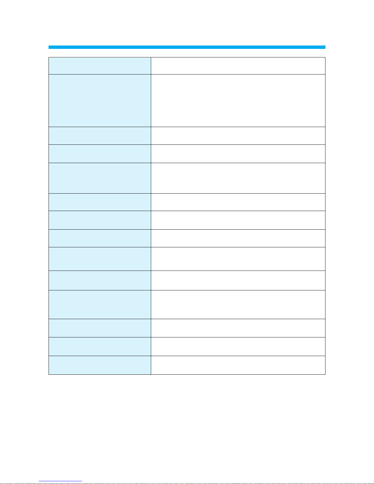
Table 1: Rating for selected areas
* Class II model only.
Note: This table is unofficial and for reference only. Be sure to confirm the precise values for your particular country
and locality.
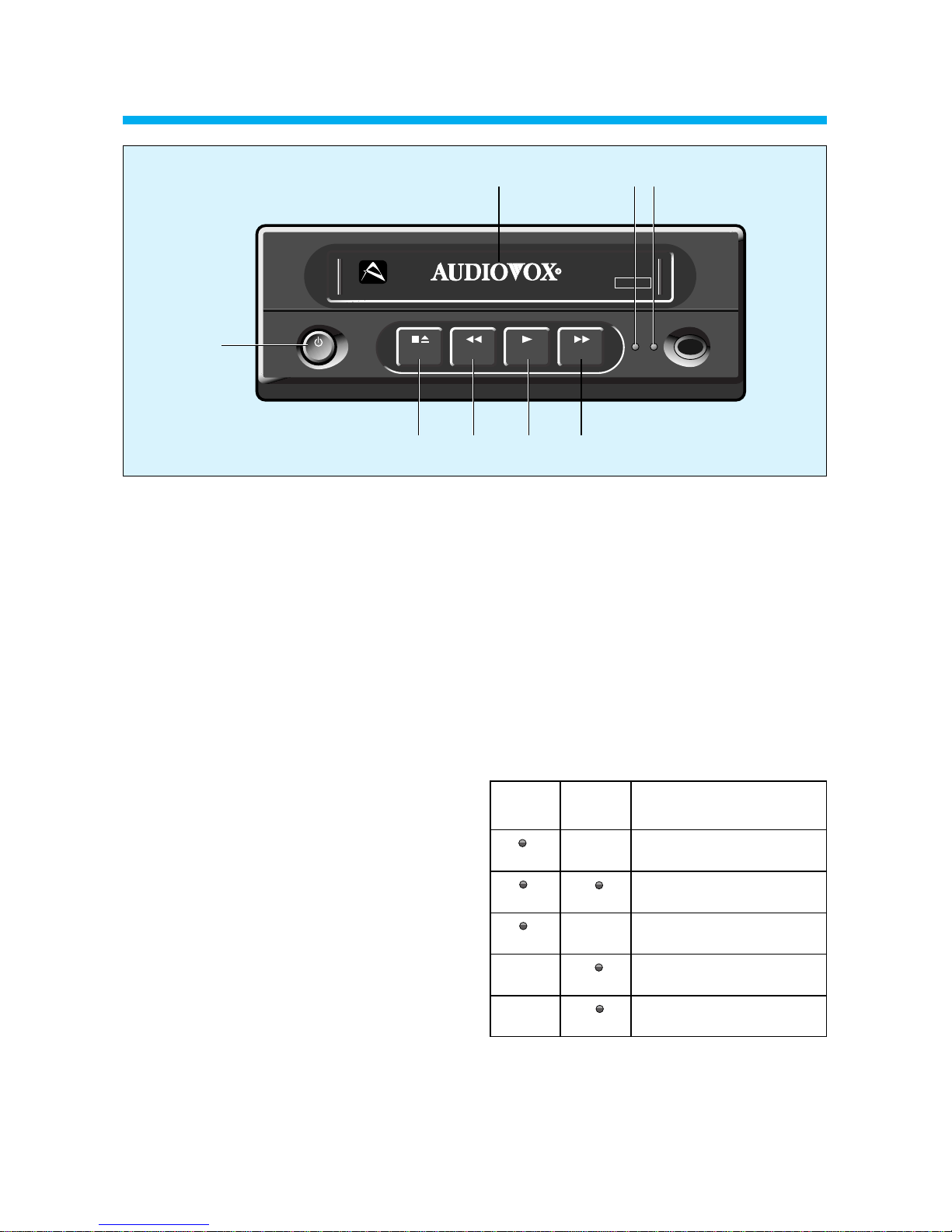
4. Leakage current test
Confirm specified or lower leakage current between B (earth ground, power cord plug prongs) and externally
exposed accessible parts (RF terminals, antenna terminals, video and audio input and output terminals, microphone
jacks, earphone jacks, etc.)
Measuring Method: (Power ON)
Insert load Z between B (earth ground, power cord plug
prongs) and exposed accessible parts. Use and AC
voltmeter to measure across both terminals of load Z.
See figure and following table.
Table 2: Leakage current ratings for selected areas
Note: This table unofficial and for reference only. Be sure to confirm the precise values for your particular country and
locality.
Z
Exposed
accessible
part AC Voltmeter
(high impedance)
Earth Ground
power cord plug prongsB
Fig. 2
AC Line Voltage Region Insulation Dielectric Clearance
Resistance Strength Distance (d), (d')
100V Japan ≥1 MΩ/500 V DC 1kV 1 minute ≥3 mm
110 to 130V USA & – – – 900V 1 minute ≥3.2mm
Canada
* 110 to 130 V Europe ≥10 MΩ/500 V DC 4 kV 1 minute ≥6 mm (d)
200 to 240 V Australia ≥8 mm (d')
(a: Power cord)
Fig. 1
d
Primary circuit terminals
Chassis
d'
a
AC Line Voltage Region Earth Ground
Load Z Leakage Current (i) (B) to:
100V Japan ¡ ≤1m A rms Exposed accessible
parts
110 to 130 V USA & ¡ ≤0.5 m A rms Exposed accessible
Canada parts
¡ ≤0.7 m A peak Antenna earth
110 to 130 V Europe ¡ ≤2 m A dc terminals
200 to 240 V Australia ¡ ≤0.7 m A peak Other terminals
¡ ≤2 m A dc
1k
1.5k
1.5kµF
2k
50k

TOTAL CONTENTS
1
SECTION 1. GENERAL....................................................................................................................2
SECTION 2. CABINET & MAIN FRAME.........................................................................................6
SECTION 3. ELECTRICAL.............................................................................................................13
SECTION 4. MECHANISM.............................................................................................................34

SECTION 1. GENERAL
2
CONTENTS
1-1. SPECIFICATIONS............................................................................................................................3
1-2. IDENTIFICATION AND OPERATION OF CONTROLS...............................................................4

* Design and specifications subject to change without notice.
1-1. SPECIFICATIONS
3
FORMAT VHS standard
Playback System Video: 2 rotary hends helical scanning system.
-Luminance; FM azimuth Playback.
-Croma; Converted sub-carrier phase shift Playback.
Audio: 2 rotary hends helical scanning system.
-Luminance; FM azimuth Playback.
-Croma; Converted sub-carrier phase shift Playback.
Video Signal System NTSC type color signal
Tape Width 12.65mm (1/2 inch)
Tape Speed SP: 33.35 mm/s
LP: 16.67 mm/s
SLP: 11.12 mm/s
Maximum PlayBack Time 480min. with T-160 Video cassette tape (SLP MODE)
FF/REW Time Less than 5 min
Power input DC 12V 12W
Out Level Video: VIDEO OUT jack 1.0Vp-p 75Ωunbalanced
Audio: AUDIO OUT jack 10KΩunbalanced
Video Horizontal Resolution More than 230 Lines
Signal-to-Noise Ratio Video : better than 43 dB
Audio : better than 40 dB
HiFi Audio: better than 60dB
Operating Temperature 5°C~40°C (41°F-104°F)
Weight NET: 3.4KG, GROSS
Dimensions 265x91x295 (WHD)mm

1-2. IDENTIFICATION AND OPERATION OF CONTROLS
4
!Casette compartment
@Power key
When the power is supplied for the set, the power
indicator lamp will always light up in red.
The Power ON and Power OFF mode will be toggled
by pressing this key.
When the POWER is switched on, the power lamp will
light up in red and the other keys will light up in green.
#Stop/Eject key
Press this key to stop tape and once more to eject
tape.
$Rewind/Review key
If this key is pressed in the PLAYBACK mode, the
VCP enters the reverse picture search mode. If
pressed in STOP mode, then the tape will rewind at
high speed.
The REW indicator lamp will light up in orange.
%PLAY key
Press this key to playback a recorded tape, or to
release special operations such as the search modes.
In the playback mode the playback indicator lamp will
be light in orange, and in Auto Tracking mode, this
indicator lamp will blink.
^Fast Fonward/ Cue key
If this key is pressed in the PLAYBACK mode, the
VCP enters the forward picture search mode. If
pressed in STOP mode, then the tape will fast
forward at high speed.
The FF indicator lamp will light up in orange.
&Cassette-In lamp/ Hi-Fi L
When the cassette is inserted, the CST-IN lamp will
light up in red.
And in the stereo or Hi-Fi L output mode, the lamp will
light up in green.
*DEW lamp/ Hi-Fi R
This indicator will flash (if power is on) to indicate
excessive moisture has been inside of VCP. This unit
will not operate until it dries out sufficiently (the tape
can be ejected from the unit). When DEW mode has
been activated, leave the unit on to allow it to dry out
completely.
And in the stereo or Hi-Fi R output mode, the lamp will
light up in green.
POWER
STOP/
EJECT REW PLAY FF
CST IN DEW
!
#
@
$%^
L - Hi-Fi - R
REMOTE
SENSOR
AVP-7180
Hi-Fi
STEREO
DIGITALAUTOTRACKING/FULL AUTOMATIC SYSTEM
&*
CST-in
&
Hi-Fi L
RED
GREEN
GREEN
DEW
&
Hi-Fi R
GREEN
CST-in or
PLAYBACK in normal Audio mode.
PLAYBACK in Hi-Fi STEREO Audio
mode.
PLAYBACK in Hi-Fi L Audio mode.
DEW mode.
CST IN
L - Hi-Fi
CST IN
L - Hi-Fi
CST IN
L - Hi-Fi
GREEN
RED
DEW
Hi-Fi - R
DEW
Hi-Fi - R
DEW
Hi-Fi - R

5
!FUSE HOLDER
This main line fuse is accessible with the external fuse
holder simply by unscrewing the cap. If the main line
fuse should blow then replace the fuse with a proper
rated fuse (125V, 2A).
@RF. OUT CHANNEL SELECTION SWITCH
Set to channel 3 or 4, whichever is not being
broadcast in your area.
#ANT. IN
Connect the TV antenna to this terminal.
$VIDEO OUT
Connect this terminal to VIDEO IN terminal of your
television, using the RCA cord provided.
%AUDIO OUT L/R
Connect this terminal to AUDIO IN terminal of your
television, using the RCA cord provided.
^RF OUT
Connect this terminal to antenna terminal of your
television, using the coaxial cable.
&* DC JACK IN
Connect this jack to DC Source (DC 12V).
* Connector description for &
DC 12V
VIDEO
AUDIO
L
R
ANT.
IN
RF
OUT
CH. 4
3
125V 2A
&*^
%
@# $!

SECTION 2. CABINET & MAIN FRAME
6
CONTENTS
2-1. CABINET DISASSEMBLY..............................................................................................................7
1) COVER TOP
2) COVER BOTTOM
3) PANEL FRONT AS.
2-2. CIRCUIT BOARD DISASSEMBLY.................................................................................................9
1) PCB MAIN AS.
2-3. EXPLODED VIEW..........................................................................................................................10
1) MAIN CHASSIS
2) PANEL FRONT
2-4. PACKING ASSEMBLY..................................................................................................................12

2-1. CABINET DISASSEMBLY
7
1) COVER TOP
• Remove four screws (see Fig 2-1)
• Lift the COVER TOP with holding the back of it and remove it.
2) COVER BOTTOM
• Remove one screw to remove the COVER BOTTOM (see Fig 2-2)
Fig. 2-1
Fig. 2-2

3) PANEL FRONT AS.
• Remove the COVER TOP. (See Fig 2-1)
• Remove the COVER BOTTOM. (See Fig 2-2)
• Press five stoppers in direction of the arrows to disengage - the top side of the panel front toward - to remove it
(See Fig 2-3).
8
Fig. 2-3

9
2-2. CIRCUIT BOARD DISASSEMBLY
1) PCB MAIN AS.
• Remove six screws and disassemble the DECK mechanism. (see Fig 2-5A)
•Press two stoppers in direction of the arrow (see Fig 2-5B) and separate the Main Chasis from the Main PCB by
lifting the PCB (see Fig 2-5C).
FIg. 2-5
(A) (C)(B)

2-3. EXPLODED VIEW
10
1) MAIN CHASSIS ASS'Y
No. PART CODE Part Name Q'ty Description Remark
1 97P0610410 CHASSIS MAIN 1 HI-PS(V0)
2 97P0800600 LEG 2 SBR 80 BLK
3 97PP318910 PANEL FRONT AS 1 DV-S102NY
4 97P0471310 COVER BOTTOM 1 SECC TO . 4
5 7173401211 SCREW TAPPTITE 1 TT2 BIN 4X12 MFZN
COVER BOTTOM FIX
6 97PE101600 PCB MAIN AS 1 DV-S104NY-RJ
6-1 97PB239600 CASE SHI PREAMP AS 1 DV-S104NY-RJ
7 97P0471200 COVER TOP 1 SECC TO.5
8 7173401212 SCREW TAPPTITE 4 TT2 BIN 4X12 BK COVER TOP FIX
9 7173401211 SCREW TAPPTITE 4 TT2 BIN 4X12 MFZN DECK AS FIX
10 7173401211 SCREW TAPPTITE 2 TT2 BIN 4X12 MFZN F/L FIX
11 7003300611 SCREW MACHINE 1
BIN 3X6 MFZN FOR CD PCB
DEW SENSOR FIX
12 97PC0211D- DECK TOTAL AS 1 VDN-8300

11
2) PANEL FRPMT ASS'Y
No. PART CODE Part Name Q'ty Description Remark
1 97P0318900 PANEL FRONT 1 HI-PS(VO)
2 97P1358300 KNOB FUNCTION 1 ABS(NATURAL)
3 97P4217300 CUSHION DOOR 1 FELT T1.0
4 97P3038000 SPRING F/L DOOR 1 SWPB 1082J
5 97P1820800 DOOR F/L 1 ABS
6 97P1622000 WINDOW REMO 1 PMMA
7 97P1713400 INDICATOR DEW 1 GPPS

12
2-4. PACKING ASSEMBLY
No. PART CODE Part Name Q'ty Description Remark
1 97P4925400 PAD FRONT/BACK 1 EPS
2 97P4801300 POLYBAG FOR SET 1 P.E FOAM
3 97P5045900 BOX CARTON 1 EX225*K200*EX225
4 97P9560000 MANUAL OWNERS 1
ALL MODEL(DV-S102N-SJ)
5 97P88OP315 CABLE RCA 1 2P-2P 1.5M
6 97P0424100 COVER ACCESSORY 2 LD-PE TO.1
7 97P7703100 PLUG DC CAR 1 DLP-1033A5

1) SERVO-LOGIC CIRCUIT ADJUSTMENT METHOD
• VIDEO HEAD SWITCHING POSITION
1) Play back the test tape.
2) Set the oscilloscope in the CHOP mode connect the CH1 to SW pluse PT01 3 PIN the CH2 to VIDEO OUT with CH1
triggering.
3) Adjust RV501 for the positive trigger until 6.5H ±0.5H cycles before the vertical SYNC pluse.
3-1. ELECTRICAL ADJUSTMENT
14
SECTION 3. ELECTRICAL
13
CONTENTS
3-1. ELECTRICAL ADJUSTMENT......................................................................................................14
1) SERVO-LOGIC CIRCUIT ADJUSTMENT METHOD
3-2. CIRCUIT DIAGRAMS....................................................................................................................15
1) CONNECTION DIAGRAM
2) POWER CIRCUIT DIAGRAM
3) SERVO SYSCON CIRCUIT DIAGRAM
4) VIDEO/NOR & AUDIO CIRCUIT DIAGRAM
5) HI-FI/PRE-AMP CIRCUIT DIAGRAM
6) A/V IN/OUT CIRCUIT DIAGRAM
3-3. COMPONENTS LOCATION GUIDE ON PCB............................................................................23
1) PCB & CONNECTOR GUIDE
2) COMPONENTS LOCATION GUIDE
3-4. ELECTRICAL PART LIST.............................................................................................................25
1) STANDARD PART NUMBER CODING
2) ELECTRICAL PART LIST BY ASSEMBLES
Adj. Location Checking Point Measuring Equipment Mode Test Tape
RV501 PT01 3 PIN Oscilloscope Play DN-1
VIDEO OUT
SWITCHING
SW30Hz
PULSE
VIDEO
OUTPUT
V. SYNC
6.5H±0.5

3-2. CIRCUIT DIAGRAMS
15
1) CONNECTION DIAGRAM

16
2) POWER CIRCUIT DIAGRAM

17
1-1 IC504 #1 PLAY MODE: AC
VOLT/DIV 500mV/DIV
TIME/DIV 5ms/DIV
1-3 P502 #6 PLAY MODE: DC
VOLT/DIV 1V/DIV
TIME/DIV 2ms/DIV
1-2 IC601 #29 PLAY MODE: DC
VOLT/DIV 1V/DIV
TIME/DIV 5ms/DIV
1-4 P502 #3 PLAY MODE: DC
VOLT/DIV 1V/DIV
TIME/DIV 53ms/DIV
1-5 IC501 #30 PLAY MODE: DC
VOLT/DIV 1V/DIV
TIME/DIV 2m/DIV

18
3) SERVO SYSCON CIRCUIT DIAGRAM

19
2-1 IC301 #29 PLAY MODE: AC
VOLT/DIV 100mV/DIV
TIME/DIV 10ms/DIV
2-3 IC302 #3 PLAY MODE: AC
VOLT/DIV 100mV/DIV
TIME/DIV 10ms/DIV
2-2 IC302 #1 PLAY MODE: AC
VOLT/DIV 100mV/DIV
TIME/DIV 10ms/DIV
2-4 IC301 #39 PLAY MODE: AC
VOLT/DIV 500mV/DIV
TIME/DIV 10ms/DIV
2-6 IC301 #59 PLAY MODE: AC
VOLT/DIV 200mV/DIV
TIME/DIV 0.5ms/DIV
2-5 IC301 #6 PLAY MODE: AC
VOLT/DIV 50mV/DIV
TIME/DIV 0.5ms/DIV
Other manuals for AVP-7180
2
Table of contents
Other Audiovox VCR System manuals

Audiovox
Audiovox VBP3000 User manual

Audiovox
Audiovox AVP-7180 User manual

Audiovox
Audiovox VCP-752 User manual

Audiovox
Audiovox AVP-7280A User manual

Audiovox
Audiovox VE1040 - Owners/installation Guide User manual

Audiovox
Audiovox AVP-7200A User manual

Audiovox
Audiovox AVR-1228 User manual

Audiovox
Audiovox AVP8280 - Mobile Hi-Fi Video Cassette Player User manual

Audiovox
Audiovox AVR-1040 User manual

Audiovox
Audiovox AVP7380 - AVP 7380 - VCP Setup guide