AUKS AFC-300CA/4 User manual

1
Technical Manual
FanCoil Unit
(Four-way Cassette Type)

2
Contents
Part 1General description............................................................................................................... 3
Part 2Unit information......................................................................................................................5
Part 3Product selection.................................................................................................................32
Part 4Controller............................................................................................................................... 35
Part 5Trouble shooting.................................................................................................................. 44

AUKS-Fan Coil
3
P a r t 1General description
1 . 1 Nomenclature

AUKS-Fan Coil
4
1.2Unit appearance
Serie
s
Range ofthe A i r Volume(CFM)
Four-
way
Cass
ette
300CFM
400CFM
500CFM
600CFM
800CFM
1000CFM
1200CFM
1400CFM

AUKS-FanCoil
5
P a r t 2.U n i t
2.1Feature..............................................................................................................................5
2.2Specfication ..................................................................................................................... 7
2.3Capacity amendment ......................................................................................................9
2.4Dimension...................................................................................................................... 13
2.5Electrical wiring andconnection..................................................................................14
2.6Installation ......................................................................................................................15
2.7Explode v i e w ............................................................................................................... 221

AUKS-FanCoil
6
2.1Feature
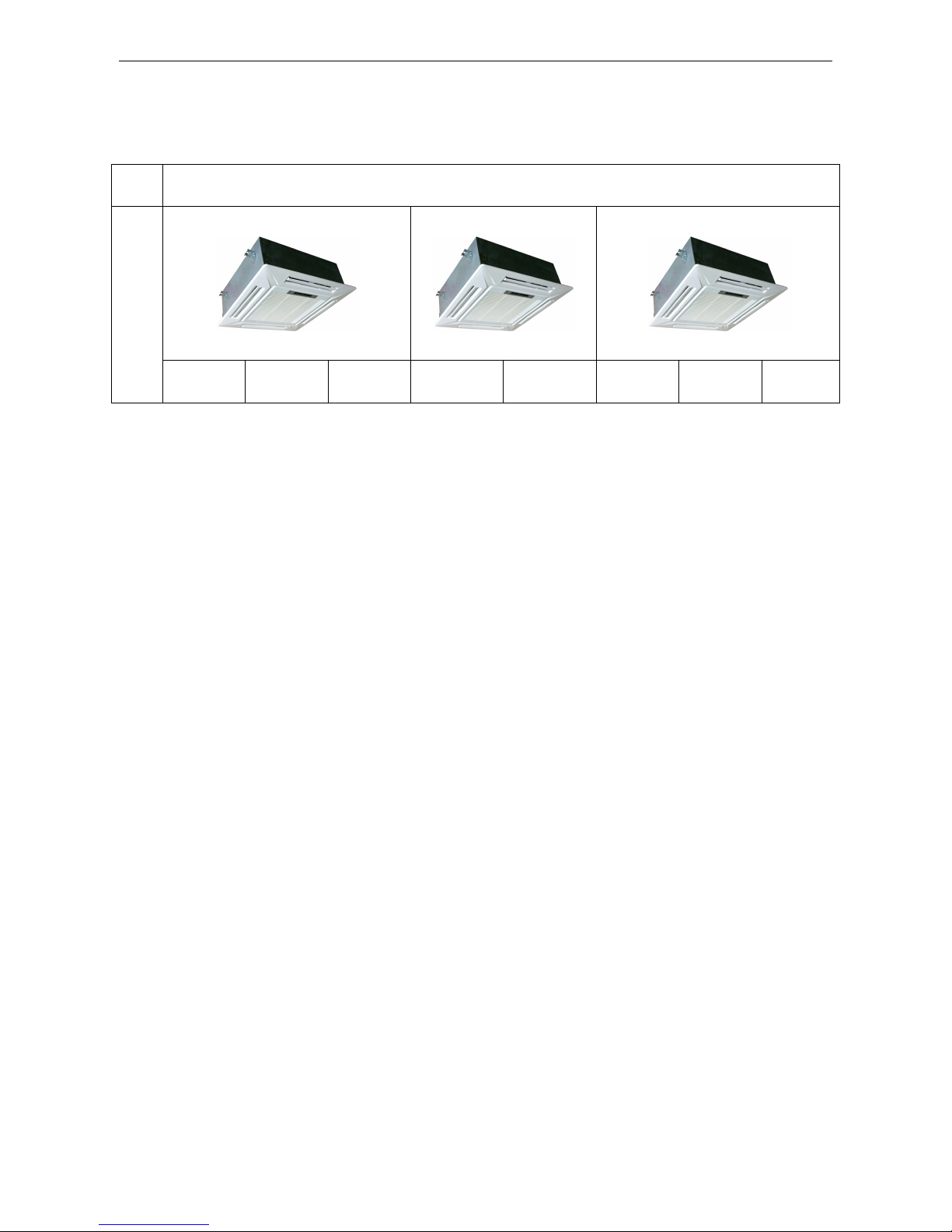
Four-way cassette fan coil unit is installed under the ceiling, compared with Floor &Standing type A/C, it
has following advantages: saving room space; Ceiling installation combining with the decoration,
makes the room more elegant; Flexible installation in anywhere in the ceiling and 4-direction blowing,
makes the indoor temperature is even and makes you feel more comfortable, so Cassette type A/C is a
perfect replacing Product of Floor &Standing type A/C.
Application occasions:
Small super market,restaurant, office, meeting room, villa,meeting room, livingroom a n d soo n , a n d i t
caneven b e u s e d a s t h e updating product formodern residential A/C.
Features:
◇Concealed design, ceiling installation, room space saving, i t i s v e r y suitable forfamily o r office
occasion;
◇WithSetting o r Auto t w o operation modes, four-way blowing, strongcirculating w i n d , multiw i n d speed,
t h e cooling o r heating capacity canreach t o e a c h corner o f t h e room;
◇One-step formed shell b y mold,appearance i s elegant;
◇Special insulation design, achieves high heat insulation efficiency, a n d n o condensation o n shell;
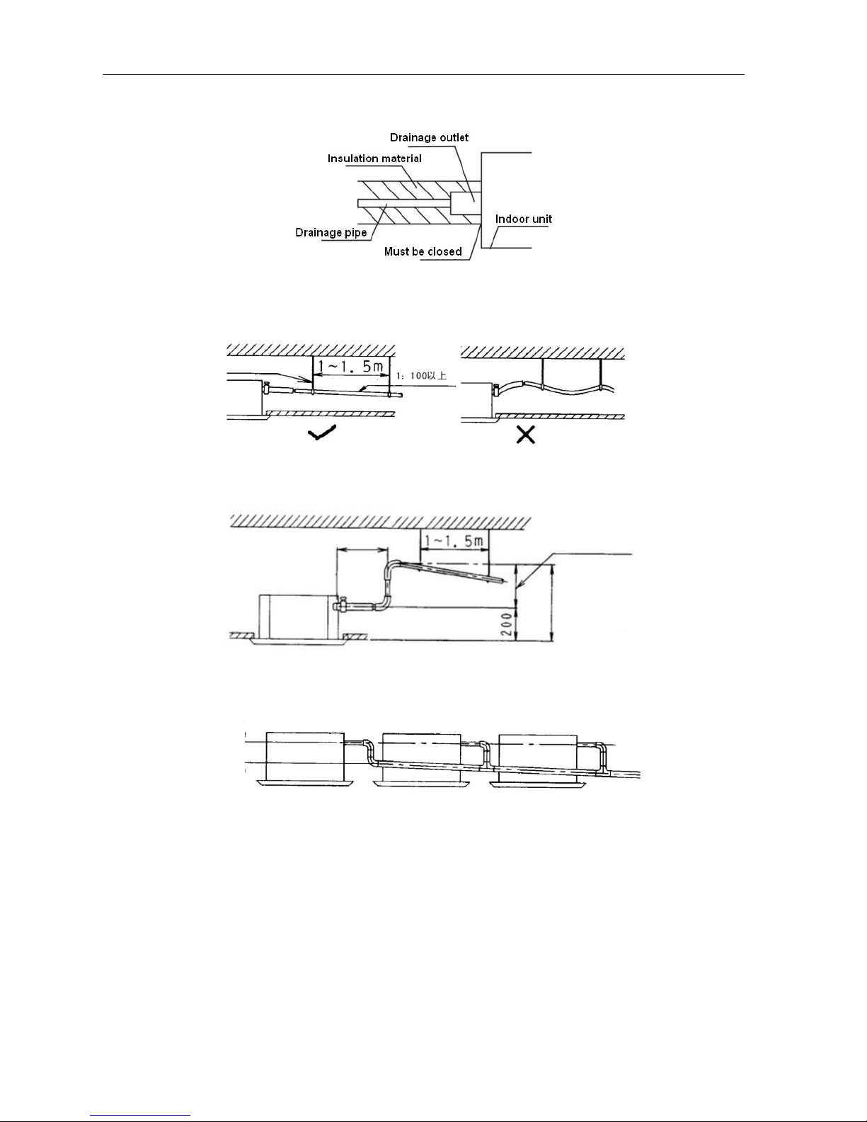
◇Built-in d r a i n pump, drain-head height i s u p t o 1.2meters, creating t h e ideal solution forperfect w a t e r
drainage, a l s o construction a n d installation i s mucheasier a n d convenient;
◇Long t e r m a i r filter, w a s h period i s t w o t i m e s longer t h a n normal filter, a n d maintenance i s free;
◇3 D helix a i r blade ensures t h e a i r flowsufficiently, reduces t h e u n i t thickness, a n d reduces t h e
operation n o i s e greatly;
◇Plastic d r i p t r a y adopts innovative foam-PS combined w i t h plastic technical, t h e thickness o f plastic
reaches 1 m m , a v o i d a n y leakage;
◇6segments heat exchanger, increase exchanging area, t h e efficiency o f heat exchanging increased
b y 10%~15%;
◇Ingenious hook design, t h e panel i s convenient t o install o r remove;
◇F r e s h a i r intake design, leading i n fresha i r t o improve indoor a i r quality anytime;
◇3-phase power supply t y p e u n i t s w i t h l o w ambient temperature cooling function, w h i c h makes t h e u n i t
canrun normally o n t h e condition t h a t t h e ambient temperature f a l l s down t o -15℃ ;
◇Auto-restart function;
◇Standard remote controller a n d optional w i r e d controller;
◇F a i l u r e automatic detection, i f t h e r e i s afailure, t h e indicator w i l l flasha n d t h e failure codewill display
o n t h e w i r e d controller, t h e failure cause i s easier t o b e found.

AUKS-FanCoil
7
Function Introduction
Type
Item
AFC-**CA/4
AFC-**CA/4A
300
400
500
600
800
1000
1200
1400
Protect
Drainage failure alarm
●
●
●
●
●
●
●
●
Sensor failure alarm
●
●
●
●
●
●
●
●
Failure codedisplay
●
●
●
●
●
●
●
●
Comfort
Cooling
●
●
●
●
●
●
●
●
Heating
●
●
●
●
●
●
●
●
3-Speed
●
●
●
●
●
●
●
●
Adjustable ESP
-
-
-
-
-
-
-
-
Auto-restart(Optional)
●
●
●
●
●
●
●
●
Timing ON/OFF
●
●
●
●
●
●
●
●
Operation
T i m e display
●
●
●
●
●
●
●
●
Operation modedisplay
●
●
●
●
●
●
●
●
Fanspeed display
●
●
●
●
●
●
●
●
Timing ON/OFF display
●
●
●
●
●
●
●
●
Windangle display
●
●
●
●
●
●
●
●
Sleeping modedisplay
●
●
●
●
●
●
●
●
Running
Auto start
●
●
●
●
●
●
●
●
Dehumidifying
●
●
●
●
●
●
●
●
Ventilation function
●
●
●
●
●
●
●
●
Health
Washable airfilter
●
●
●
●
●
●
●
●
Freshairinterface
-
-
●
●
●
●
●
●
Installation
Left/right drainage
-
-
-
-
-
-
-
-
Left/right pipe connection
-
-
-
-
-
-
-
-
Down/back airsuction
-
-
-
-
-
-
-
-
Installation indicating board
-
-
-
●
●
●
●
●
Remarks:“●”Stands f o r “YES” “-” Stands f o r “NO”

AUKS-FanCoil
8
2.2Specfication
Model
AFC-300CA/4
AFC-400CA/4
AFC-500CA/4
AFC-600CA/4A
Air Volume
H i Speed
C F M
300
400
500
600
m 3
/h
510
680
850
1020
Medium Speed
C F M
225
300
375
450
m 3
/h
382
510
638
765
Low Speed
C F M
150
200
250
300
m 3
/h
255
340
425
510
Cooling Capacity
H i Speed
W
2712
3618
4514
5406
Medium Speed
W
2305
3075
3837
4595
Low Speed
W
1763
2352
2934
3514
Heating Capacity
H i Speed
W
4070
5418
6767
8115
Medium Speed
W
3460
4605
5752
6898
Low Speed
W
2464
3522
4399
5275
N o i s e Level
dB(A
)
≤39
≤40
≤42
≤44
FanMotor
FanQuantity
1
1
1
1
Motor Quantity
1
1
1
1
Power Input
W
50
57
67
90
WaterFlowVolume
Kg/h
620
700
940
1150
Hydraulic Resistance
kPa
26
27
29
31
M a x . Workingpressure
M P a
1.6
1.6
1.6
1.6
Dimension(W×D×H
)
Net(Body)
mm
615×615×263
615×615×263
615×615×263
835×835×250
Packing(Body)
mm
700×700×330
700×700×330
700×700×330
910×910×310
Net(Panel)
mm
650×650×55
650×650×55
650×650×55
950×950×55
Packing(Panel)
mm
710×710×80
710×710×80
710×710×80
1000×1000×10
0
Weight
Net/Gross(Body)
kg
20/21.5
20/21.5
21/22.5
24.5/28
Net/Gross(Panel
)
kg
3/5
3/5
3/5
5/7
Inlet/Outlet WaterPipe
R c 3 / 4 ″(DN20)
D r a i n Pipe
R 3 / 4 ″(DN20)
Stuffing Quantity(20/40/40H)
135/264/306
135/264/306
135/264/306
64/134/152
Note:
1 . Cooling capacity t e s t conditions:Air inlet temp.:27℃DB/19.5℃ WB,Water inlet/outlet temp.:7℃ / 1 2 ℃ .
2 . Heating capacity t e s t conditions:Air inlet temp.:21℃ DB,Water inlet/outlet temp.:60℃ .
3 . Noiselevel i s tested i n full-anechoic room.
4 . Parameters above mayb e modified a s product improvement. W e keep t h e right t o change
theproduct specifications without prior n o t i c e .

AUKS-FanCoil
9
Model
AFC-800CA/4
AFC-1000CA/4
AFC-1200CA/4
AFC-1400CA/4
Air Volume
H i Speed
C F M
800
1000
1200
1400
m 3
/h
1360
1700
2040
2380
Medium Speed
C F M
600
750
900
1050
m 3
/h
1020
1275
1530
1785
Low Speed
C F M
400
500
600
700
m 3
/h
680
850
1020
1190
Cooling Capacity
H i Speed
W
7210
9018
10810
12611
Medium Speed
W
6129
7665
9189
10719
Low Speed
W
4687
5862
7027
8197
Heating Capacity
H i Speed
W
10807
13512
16205
18901
Medium Speed
W
9186
11485
13774
16066
Low Speed
W
7025
8783
10553
12286
N o i s e Level
dB(A)
≤45
≤48
≤50
≤51
FanMotor
FanQuantity
1
1
1
1
Motor Quantity
1
1
1
1
Power Input
W
131
145
186
225
WaterFlowVolume
kg/h
1400
1680
1820
2245
Hydraulic Resistance
kPa
34
36
39
44
M a x . Workingpressure
M P a
1.6
1.6
1.6
1.6
Dimension(W×D×H)
Net(Body)
mm
835×835×250
835×835×290
835×835×290
835×835×290
Packing(Body)
mm
910×910×310
910×910×350
910×910×350
910×910×350
Net(Panel)
mm
950x950x55
950x950x55
950x950x55
950x950x55
Packing(Panel)
mm
1000x1000x100
1000x1000x100
1000x1000x100
1000x1000x100
Weight
Net/Gross(Body)
kg
25.5/29
26.5/31
28/32.5
28/32.5
Net/Gross(Panel)
kg
5/7
5/7
5/7
5/7
Inlet/Outlet WaterPipe
R c 3 / 4 ″(DN20)
D r a i n Pipe
R 3 / 4 ″(DN20)
Stuffing Quantity(20/40/40H)
64/134/152
60/122/136
60/122/136
60/122/136
Note:
5 . Cooling capacity t e s t conditions:Air inlet temp.:27℃DB/19.5℃ WB,Water inlet/outlet temp.:7℃ / 1 2 ℃ .
6 . Heating capacity t e s t conditions:Air inlet temp.:21℃ DB,Water inlet/outlet temp.:60℃ .
7 . Noiselevel i s tested i n full-anechoic room.
8 . Parameters above mayb e modified a s product improvement. W e keep t h e right t o change
theproduct specifications without prior n o t i c e .

AUKS-FanCoil
1 0
2 . 3 Capacity amendment
2.3.1 T a b l e o f variable working condition performance for cooling capacity
Table o f variable working condition performance parameter under cooling mode
U n i t : W
Air inlet temperature℃
26℃DB/18. 7℃WB
27℃D B / 1 9 ℃WB
Waterinlet temperature ℃
5
7
9
5
7
9
Model
(CFM)
Water
flow
(kg/h)
Water
pressure
drop
(kPa)
T H
SH
T H
SH
T H
SH
T H
SH
T H
SH
T H
SH
300
300
3.5
1949
1477
1723
1385
1477
1210
1990
1559
1816
1467
1529
1282
400
5.9
2223
1660
1957
1537
1680
1342
2284
1752
2018
1619
1741
1424
500
8.7
2617
1779
2310
1636
1994
1421
2678
1861
2372
1717
2055
1523
600
12
2762
1753
2458
1606
2115
1391
2831
1841
2488
1694
2184
1479
400
430
8.1
2592
1964
2292
1841
1964
1610
2646
2073
2414
1951
2032
1705
550
11.5
2956
2207
2602
2044
2234
1785
3038
2330
2684
2153
2316
1894
650
15.5
3482
2367
3074
2177
2653
1891
3564
2476
3156
2285
2734
2027
750
20
4077
2588
3629
2371
3123
2053
4179
2718
3673
2501
3224
2183
500
600
18
3227
2446
2853
2293
2446
2004
3295
2581
3006
2429
2530
2123
700
24
3679
2747
3239
2543
2781
2221
3781
2899
3340
2679
2883
2357
800
30
4127
2805
3643
2579
3143
2241
4223
2934
3740
2708
3240
2402
900
37
4548
2887
4048
2645
3483
2290
4661
3032
4096
2790
3596
2435
600
750
21.5
3860
2925
3413
2742
2925
2397
3941
3088
3596
2905
3027
2539
850
26.8
4299
3209
3784
2971
3249
2595
4418
3387
3903
3130
3368
2754
950
32.7
4768
3241
4209
2980
3632
2589
4879
3390
4321
3129
3743
2775
1050
39
5194
3297
4623
3021
3978
2615
5323
3463
4678
3186
4107
2781
800
900
14.8
5901
4472
5217
4193
4472
3665
6025
4721
5497
4441
4627
3882
1100
21
6492
4847
5714
4488
4906
3919
6672
5116
5894
4727
5086
4158
1300
28
7654
5202
6757
4783
5830
4156
7833
5441
6936
5023
6009
4455
1500
36
8129
5160
7235
4727
6226
4093
8330
5419
7321
4987
6428
4353
1000
1200
23
7107
5386
6284
5050
5386
4414
7256
5685
6621
5349
5573
4676
1400
30
8113
6056
7141
5608
6131
4897
8337
6393
7365
5907
6356
5197
1600
38
9566
6502
8445
5979
7287
5194
9790
6801
8669
6278
7511
5568
1800
46.8
10675
6776
9501
6208
8177
5375
10940
7117
9615
6549
8442
5716
1200
1500
29
8727
6614
7717
6201
6614
5420
8911
6982
8130
6568
6844
5742
1700
36
9931
7414
8741
6865
7506
5995
10206
7826
9016
7231
7780
6361
1900
42
11938
8114
10539
7461
9093
6482
12217
8487
10819
7834
9373
6948
2100
48
12423
7885
11057
7225
9515
6255
12731
8281
11189
7621
9824
6652
1400
1800
30
9394
7120
8307
6675
7120
5834
9592
7515
8752
7070
7367
6180
2000
37
10026
7485
8825
6931
7578
6053
10304
7901
9102
7300
7855
6422
2200
43
12756
8670
11261
7972
9716
6926
13055
9068
11560
8371
10015
7424
2400
50
13296
8440
11834
7732
10184
6695
13626
8864
11976
8157
10514
7120
Variable w o r k i n g condition performance parameter t a b l e (continued)

AUKS-FanCoil
1 1
Unit:W
Air inlet temperature ℃
27℃DB/19. 5℃WB
28℃D B / 2 2 ℃WB
Water inlet temperature ℃
5
7
9
5
7
9
Model
(CFM)
Water
flow
(kg/h)
Water
pressure
drop
(kPa)
T H
SH
T H
SH
T H
SH
T H
SH
T H
SH
T H
SH
300
300
3.5
2062
1529
1826
1416
1681
1410
2585
1916
2339
1813
2113
1567
400
5.9
2366
1711
2100
1578
1828
1495
2960
2140
2694
2024
2428
1755
500
8.7
2801
1840
2474
1687
2158
1599
3466
2277
3179
2168
2862
1880
600
12
2929
1822
2625
1655
2293
1553
3673
2285
3350
2112
2997
1864
400
430
8.1
2742
2032
2428
1882
2236
1876
3437
2548
3110
2411
2810
2083
550
11.5
3147
2275
2793
2098
2432
1988
3937
2847
3583
2692
3229
2334
650
15.5
3727
2449
3292
2245
2871
2128
4612
3029
4231
2885
3809
2502
750
20
4323
2689
3875
2444
3386
2292
5422
3373
4945
3118
4424
2752
500
600
18
3414
2530
3023
2344
2784
2335
4280
3173
3872
3002
3499
2593
700
24
3917
2832
3476
2611
3027
2475
4900
3543
4459
3350
4019
2905
800
30
4417
2902
3901
2660
3402
2522
5465
3590
5013
3418
4514
3117
900
37
4822
3000
4322
2725
3776
2557
6048
3762
5515
3478
4935
3070
600
750
21.5
4083
3027
3616
2803
3330
2793
5119
3795
4632
3591
4185
3102
850
26.8
4576
3308
4061
3051
3536
2891
5725
4139
5210
3914
4695
3478
950
32.7
5103
3352
4507
3073
3931
2914
6314
4148
5792
3949
5215
3730
1050
39
5507
3426
4936
3113
4313
2920
6907
4296
6299
3972
5636
3506
800
900
14.8
6242
4627
5528
4286
5090
4270
7826
5801
7081
5490
6398
4571
1100
21
6911
4996
6133
4607
5340
4366
8646
6251
7868
5911
7090
5126
1300
28
8192
5381
7235
4933
6310
4677
10135
6658
9298
6339
8371
5499
1500
36
8619
5361
7725
4871
6749
4570
10809
6724
9858
6216
8820
5487
1000
1200
23
7518
5573
6658
5162
6131
5143
9426
6987
8528
6612
7705
5712
1400
30
8636
6243
7664
5757
6673
5456
10804
7811
9832
7386
8860
6406
1600
38
10239
6726
9043
6166
7886
5846
12668
8322
11621
7924
10463
6873
1800
46.8
11318
7041
10145
6397
8863
6002
14195
8831
12946
8164
11583
7206
1200
1500
29
9232
6844
8176
6339
7528
6316
11575
8580
10473
8119
9462
6843
1700
36
10572
7643
9382
7048
8169
6680
13226
9562
12036
9042
10847
7674
1900
42
12777
8394
11285
7694
9842
7296
15808
10385
14503
9888
13057
8578
2100
48
13172
8194
11806
7445
10315
6984
16520
10276
15066
9500
13480
7888
1400
1800
30
9938
7367
8801
6823
8104
6799
12460
9236
11273
8740
10185
7207
2000
37
10673
7716
9472
7116
8248
6744
13353
9654
12152
9129
10951
8084
2200
43
13652
8969
12058
8221
10516
7795
16891
11096
15496
10565
13951
9393
2400
50
14098
8770
12636
7968
11040
7476
17681
10999
16125
10168
14428
8975

AUKS-FanCoil
1 2
2.3.2Table o f variable working condition performance for heating capacity
Table o f variable working conditionperformance parameter under heating mode
Unit:W
Air inlet temperature ℃
18℃D B
20℃D B
Waterinlet temperature ℃
40
45
50
60
70
80
40
45
50
60
70
80
Model
(CFM)
Water
flow
(kg/h)
Water
pressure
drop
(kPa)
300
300
3.5
1905
2335
2776
3637
4498
5370
1733
2174
2593
3465
4337
5198
400
5.9
1988
2438
2898
3798
4708
5607
1810
2260
2710
3620
4519
5430
500
8.7
2091
2571
3040
3989
4948
5886
1908
2377
2856
3815
4754
5713
600
12
2223
2740
3236
4239
5252
6265
2026
2523
3040
4042
5056
6069
400
430
8.1
2531
3103
3689
4833
5977
7135
2302
2888
3446
4604
5763
6906
550
11.5
2716
3331
3960
5189
6433
7663
2473
3088
3703
4946
6176
7420
650
15.5
2991
3677
4349
5706
7077
8420
2729
3400
4086
5458
6800
8172
750
20
3276
4038
4769
6247
7740
9233
2986
3718
4479
5957
7451
8944
500
600
18
3158
3871
4603
6030
7457
8903
2872
3604
4300
5745
7190
8617
700
24
3276
4018
4776
6259
7759
9242
2983
3724
4466
5966
7449
8949
800
30
3486
4285
5067
6648
8246
9811
3180
3962
4761
6359
7923
9522
900
37
3656
4506
5323
6972
8639
10305
3333
4149
5000
6649
8316
9982
600
750
21.5
3832
4698
5586
7318
9050
10803
3486
4373
5218
6971
8725
10457
850
26.8
4005
4911
5838
7651
9485
11297
3646
4553
5459
7293
9105
10939
950
32.7
4098
5038
5958
7817
9696
11535
3738
4658
5598
7477
9316
11195
1050
39
4181
5153
6087
7973
9879
11784
3811
4745
5717
7603
9509
11415
800
900
14.8
5284
6478
7701
10089
12477
14895
4806
6030
7194
9612
12030
14418
1100
21
5671
6954
8267
10834
13431
15998
5163
6447
7730
10327
12894
15490
1300
28
6117
7520
8892
11668
14473
17218
5580
6953
8355
11160
13906
16711
1500
36
6548
8071
9533
12487
15472
18457
5970
7431
8954
11909
14893
17878
1000
1200
23
6597
8088
9616
12597
15579
18598
6001
7529
8982
12001
15020
18002
1400
30
7086
8690
10331
13538
16783
19991
6452
8056
9660
12904
16112
19357
1600
38
7645
9398
11113
14581
18087
21517
6974
8689
10442
13947
17378
20884
1800
46.8
8169
10069
11893
15579
19303
23026
7447
9271
11171
14857
18581
22304
1200
1500
29
7916
9705
11539
15116
18694
22317
7200
9034
10778
14401
18023
21601
1700
36
8490
10412
12378
16221
20109
23952
7731
9652
11574
15461
19305
23192
1900
42
9554
11744
13888
18222
22603
26890
8715
10859
13049
17430
21717
26098
2100
48
9612
11848
13994
18331
22712
27093
8763
10909
13144
17481
21863
26244
1400
1800
30
8795
10782
12819
16795
20770
24794
8000
10037
11975
16000
20024
23999
2000
37
9440
11576
13762
18035
22358
26630
8595
10732
12868
17190
21463
25785
2200
43
10460
12858
15205
19951
24747
29441
9542
11889
14287
19083
23777
28573
2400
50
10849
13372
15795
20689
25635
30580
9891
12313
14835
19730
24676
29621
Table o f cvariable w o r k i n g condition performance parameter under heating mode(continued)

AUKS-FanCoil
1 3
Unit:W
Air inlet temperature ℃
21℃D B
22℃D B
Water inlet temperature ℃
40
45
50
60
70
80
40
45
50
60
70
80
Model
Water
flow
(kg/h)
Water
pressure
drop
(kPa)
300
300
3.5
1657
2077
2507
3379
4251
5101
1560
1980
2421
3293
4154
5015
400
5.9
1716
2176
2626
3536
4436
5346
1622
2082
2532
3431
4342
5241
500
8.7
1806
2285
2754
3703
4662
5600
1714
2183
2662
3611
4560
5519
600
12
1933
2430
2936
3939
4952
5965
1820
2326
2822
3836
4849
5872
400
430
8.1
2202
2760
3332
4490
5648
6778
2073
2631
3217
4376
5520
6664
550
11.5
2345
2974
3588
4832
6061
7305
2216
2845
3460
4689
5933
7162
650
15.5
2583
3269
3940
5297
6669
8011
2452
3123
3809
5166
6523
7894
750
20
2849
3581
4327
5805
7298
8791
2682
3428
4159
5653
7146
8654
500
600
18
2747
3443
4157
5602
7047
8457
2587
3283
4014
5459
6887
8314
700
24
2828
3586
4328
5828
7311
8811
2673
3431
4173
5655
7156
8639
800
30
3009
3809
4591
6172
7770
9335
2856
3639
4438
6019
7600
9198
900
37
3180
3996
4829
6479
8146
9812
2993
3826
4642
6309
7975
9659
600
750
21.5
3334
4178
5044
6798
8552
10262
3139
3984
4871
6625
8357
10089
850
26.8
3457
4384
5290
7124
8937
10770
3267
4194
5101
6913
8747
10560
950
32.7
3539
4478
5398
7257
9136
10975
3359
4278
5218
7077
8936
10816
1050
39
3636
4570
5523
7409
9315
11220
3423
4375
5309
7215
9120
11045
800
900
14.8
4597
5761
6955
9373
11791
14149
4328
5492
6716
9134
11522
13910
1100
21
4895
6208
7491
10088
12655
15251
4626
5939
7223
9790
12386
14953
1300
28
5282
6684
8057
10832
13637
16382
5013
6386
7788
10563
13339
16144
1500
36
5695
7157
8650
11604
14589
17574
5360
6853
8315
11299
14284
17299
1000
1200
23
5740
7193
8684
11703
14722
17666
5404
6858
8386
11405
14386
17368
1400
30
6117
7758
9361
12606
15813
19058
5781
7422
9026
12233
15478
18685
1600
38
6600
8353
10069
13537
17042
20473
6265
7980
9733
13201
16670
20175
1800
46.8
7105
8929
10791
14477
18201
21924
6688
8549
10373
14097
17821
21583
1200
1500
29
6887
8632
10420
14043
17666
21199
6485
8229
10063
13685
17263
20841
1700
36
7328
9295
11216
15104
18947
22835
6926
8893
10814
14657
18545
22388
1900
42
8248
10439
12583
16917
21298
25585
7829
9973
12163
16498
20832
25212
2100
48
8360
10507
12697
17034
21415
25797
7869
1059
12205
16587
20968
25395
1400
1800
30
7652
9590
11577
15602
19627
23552
7205
9143
11180
15204
19180
23155
2000
37
8148
10334
12471
16793
21066
25388
7701
9887
12023
16296
20619
24891
2200
43
9031
11430
13777
18522
23318
28013
8572
10919
13317
18063
22808
27604
2400
50
9436
11859
14331
19226
24171
29117
8881
11354
13776
18721
23667
28662

AUKS-FanCoil
1 4
2 . 4 Dimension
AFC-300CA/4,AFC-400CA/4,AFC-500CA/4
AFC-600CA/4A,AFC-800CA/4A
AFC-1000CA/4A,AFC-1200CA/4A,AFC-1400CA/4A

AUKS-FanCoil
1 5
2 . 5 Electrical wiring a n d connection
Introduction o f control board QFPD-3F-HCE2 (PCB) sockets
Transformer
input
Electric
heater output
Power
Line plug
Heat water
valve output
C o l d water
valve output
Drainage
pump output
Neutra
plug
4-DIPswitch
Floatswitch
Indoor
temperature
sensor input
Wiredcontrol
receiver
3-DIP
switch
Step motor
output
Display board
output
Transformer
output
Buzzer
Indoor f a n output
High
M i d
L o w
Neutral

AUKS-FanCoil
1 6
2 . 6 Installation
2.6.1 Preparation andequipment before installation
Preparation b e f o r e installation
Please buy the following accessory parts from the
market
Besides common tools, the followings arealso
needed.
Hung bolts M12, 4pcs.
T w o wrenches, one ofthem istorque spanner
Drainage pipe PVC
N y l o n cableties(big size)5pcs(small size)5pcs.
Power cable
Installation precaution
◇Hanging location should b e a b l e t o support t h e u n i t ’ s weight, t h e r e should b e n o increase i n noise and
vibration. I f t h e hanging location needs reinforcement, i t should b e reinforced before installation;
◇Choose t h e space above t h e ceiling t h a t canp u t t h e indoor u n i t inside;
◇Thelocation should b e e a s y fordrainage;
◇Whenconnecting inlet a n d outlet w a t e r pipe, i t ’ s recommended t o u s e flexible connecting p i p e a n d
PTFE t a p e forsealing w i t h torque forcen o moret h a n 205.6N.m (21Kgf.m)
◇Inlet a n d outlet o f w a t e r pipe should b e insulated w i t h P E foam material and equipped w i t h valves.
◇Thewater i n t h e circulatory systemshould b e clean,and filter needs t o b e installed a t t h e w a t e r .
Inlet,to prevent coilblockage,
◇Before power o n , please check i f t h e voltage, frequency a n d phase o f power supply comply w i t h t h e
requirements o f u n i t . Voltage deviation o f power supply shouldn’t b e o v e r 1 0 % o f rated voltage.
◇Theinlet water temperature should b e n o l e s s t h a n 6℃(prevent condensation)under cooling and n o
moret h a n 6 0 ℃under heating.
◇Theu n i t should n o t b e installed i n t h e heat source, steamsource o i l mistplaces (such a s machine
room, kitchen, laundry room, mechanical workshop, e t c . ) i n order t o avoid performance degradation,
e l e c t r i c shock, plastic p a r t s corrosion w h i c h l e a d t o u n i t broken;
◇Choose t h e location a t l e a s t 1metera w a y fromTVa n d radio, i n order t o avoid interference t o t h e m
◇There i s n o obstacles getting i n t h e w a y o f a i r circulation, colda i r canevenly spread t o a l l corners o f
t h e room;
◇I n order t o facilitate maintenance a n d repair, t h e r e should b e certaindistance between indoor unit and
obstacles;
2.6.2U n i t installation
The distance between indoor unit a n d obstacle

AUKS-FanCoil
1 7
Unitsuspension
◇Select t h e suspension foundation:
Thesuspension foundation i s astructure o f either wooden f r a m e o r reinforced concrete. I t mustb e
firma n d reliable t o bear a t l e a s t 4t i m e s weight o f i t s e l f a n d capable o f bearing vibration forl o n g
periods.
◇Fixing o f suspension foundation:
◇F i x t h e suspension b o l t s either a s shown i n t h e picture o r b y asteelo r wooden bracket.
◇I f t h i s u n i t i s installed o n asloping ceiling, acushion b l o c k should b e installed between t h e ceiling a n d
t h e a i r outlet panel, i n order t o ensure t h a t t h e u n i t i s installed o n alevel surface.
Thisi s a s showni n t h e drawing a s follows:
◇Adjust t h e relative position o f t h e suspension hook o n t h e suspension b o l t sot h a t t h e u n i t canb e i n
l e v e l position i n a l l directions. Checkw i t h alevel gauge after t h e installation i s complete i n order t o
ensure t h a t t h e indoor u n i t i s horizontal, otherwise i t will cause w a t e r leakage, a i r leakage e t c .
◇Tighten t h e b o l t a n d ensure t h a t four hooks a r e i n close contact w i t h t h e n u t s a n d washers, a n d t h e
unit i s suspended firmly a n d reliably o n t o t h e hooks.
◇After t h e unit i s installed ensure i t i s secure a n d does n o t shake o r sway.
◇Ensure t h a t t h e centreo f t h e indoor u n i t i s i n alignment w i t h t h e centreo f t h e opening i n t h e ceiling.

AUKS-FanCoil
1 8
Drainage pipe installation
◇
Thedrain p i p e should b e properly insulated to prevent the generation o f condensation,seepicture a s
follows:
Heatinsulation material: rubber insulation pipe w i t h t h e thickness o f moret h a n 8 m m
◇Drainage pipe musth a v e adownward gradient (1/50-1/100).If t h e d r a i n pipe i s installed u p s a n d
downs, i t will cause water backflow o r leakage e t c .
Thep i p e should not risea t any point.
◇Theu n i t h a s ad r a i n pump w h i c h w i l l lift u p t o 1200mm. However after t h e p u m p stopst h e w a t e r still
i n t h e pipe will d r a i n b a c k a n d mayoverflow t h e d r a i n t r a y causing aw a t e r l e a k . F o r t h i s reason
please install the drain pipe as shown
◇Whendraining multiple u n i t s i n t o acommon d r a i n line, t h i s common d r a i n should b e installed about
100mm below e a c h units d r a i n outlet, a s showni n t h e drawing.
◇Whenfinish installation please carry o u t t h e drainage t e s t t o ensure t h a t t h e w a t e r flowthrough t h e
pipeline fluently, a n d carefully observe t h e junction t o ensure t h a t t h e r e i s n o w a t e r leakage. I f t h e u n i t
i s installed i n t h e n e w l y built house, strongly recommend t h a t t h i s t e s t t a k e n before t h e ceiling
installation. Even it is the heating only unit, this test is unavoidable.
M o r e than 1:100
M o r e than
100mm
L e s s t h a n 300mm
L e s s t h a n 600mm
(Unit: mm)
L e s s t h a n 8 0 0

AUKS-FanCoil
1 9
Panel installation
As to the MB12 panel please refer to the following picture, the panel has four hooks which attach to
corresponding hangers on the unit and the panel should be positioned using these first. The panel is
then fixed into position by four bolts which are accessed through the four corner panels on the grille.
Notes:
When installing please ensure t h a t t h e position o f swingmotori s i n accordance w i t h t h e position o f t h e
pipes o f t h e u n i t .
Connect duct, fresh a i r ventilation
I n order t o meetdifferent customers’ requirements a n d t h e i r different usage environment,
AFC-500CA/4 , AFC-600CA/4,AFC-800CA/4,AFC-1000CA/4,AFC-1200CA/4,AFC-1400CA/4
u n i t reserves o n e f r e s h a i r ventilation h o l e a n d four d u c t connection holes. Thefresha i r canb e
introduced fromoutside o r through d u c t .
◇F r e s h a i r ventilation: I n t h e corner o f t h e u n i t t h e r e i s acircular fresha i r connection hole, i f u s e r s want
t h i s feature, please cutd o w n t h e circular metalsheet a n d connect i t t o t h e duct. F r e s h a i r
replacement hole i s connected t o t h e return a i r inlet o f t h e indoor u n i t , when i n t h e process o f
operation d u e t o t h e negative pressure, t h e fresha i r canb e introduced f r o m outside.
◇Connect t o d u c t : There a r e four rectangular connection holes o n t h e four sideso f t h e unit. I f users
what t o connect i t t o t h e duct, please close t h e outlet t o t h e sidew h i c h needs connecting t o t h e d u c t
as well as cut down the rectangular metal sheet.
Notes:
1.Only under special usage t h a t i t i s allowed t o connect t o d u c t pipe and t h e length o f t h e d u c t pipe
should b e l e s s t h a n 5meters.
2 . Usingt h e d u c t t h a t canprevent frosta n d noise.
3 . Usingheat insulation material t o sealt h e junction between duct a n d t h e u n i t .

AUKS-FanCoil
2 0
2.6.3 Electrical connection precaution
Warning
Installation of electric items must be carried out by qualified, professional technicians. An isolated circuitry
should be fixed with whole-pole disconnection devices, which is with at least 3mm gap of touch point. .
Power supply and indoor to outdoor connection should use special cable. Providing the necessity of
installation or replacement, the professional technician of service store appointed by manufacturer must
be required, while self-operation by users is prohibited.
Incase ofany electric shock accident, thecreepage protection devices /power supply on-off and breaker
mustberequired w i t h power supply.
Machine mustbeearthed surely.Ifnot, it’ll beprobably caused creepage.
T h e power cordshallconsist w i r e s of227IEC53(RVV) typespecified inGB5023 orthose ofequivalent
grades orabove .Secure thew i r e s w i t h fixtures, sothat theterminals will not easily dislodge under
external forces. Incorrect connection orfixing maycause afireorother hazards. T h e internal and external
connecting cableshallconsist w i r e s of245IEC57(YZW) typespecified inGB5013 orthose ofequivalent
grades orabove.
N o t i c e
T h e earth lineisneither allowed toconnect togas pipe, water pipe orcircuitry oftelephone orlighting rod,
nor totheearth line ofother devices.
Others
● P l e a s e connect thepower cordaccording totheinstructions ofthecircuit diagram.
●Securely and firmly connect thew i r e s totheterminal holder w i t h cablefixtures, toprevent theexternal
forces fromacting onthew i r e s and causing dangers.
2.6.4Commissioning
After installation, machine canb e started commissioning.
Checkinstallation condition
◇Checku n i t installation a n d w i r e connection i n accordance w i t h t h e requirement o f service manual.
◇Check t h e power supplying, diameter o f w i r e s , a i r on-off a n d makei t suret h a t t h e i t e m s canb e
matched w i t h machines and, e a r t h w i r e connection safety.
◇Checka i r inlet/outlet d u c t a n d makei t suret h a t t h e i t e m s i s clean, operating smoothly.
Pressure Test a n d Water Filling o f Unit
Before conducting pressure t e s t o f f a n coila i r conditioner system, i t ’ s necessary t o formulate
pressure t e s t scheme a n d select appropriate pressure t e s t pump. Duringpressure test, i t ’ s necessary
t o carefully record p r e s s t e a t status timely monitor pressure change o f system.
Pay attention t o t h e following points when formulating pressure t e s t scheme:
Before filling w a t e r forcoil,vent v a l v e o n collecting head mustb e opened a n d t h e n closed until
exhausting t h e a i r i n coil.
Pressure t e s t should b e conducted under a i r temperature conditions above 5℃,otherwise,
anti-freezing measures should b e taken.
During hydraulic t e s t , increase pressure slowlya n d evenly. carefully check i f t h e r e i s w a t e r leakage a t
t h e jointafter w a t e r p u m p stopsrunning a n d hydraulic pressure stabilizes. Don’t repair i n case o f
hydraulic pressure.
As forwater filling i n t h e system,i t ’ s mandatory t o fill w a t e r b y layer, discharge b y layer a n d t e s t l a y e r
b y layer.
After confirming t h e r e i s n o leakage o n pipeline o f system,finally conduct thermal insulation treatment
according t o design scheme.
Pressure t e s t scheme o f systemshould b e formulated according t o t h e principle o f water-flowing from
l o w t o h i g h a n d injecting water layer b y layer. Moreover, t h e above points mustb e followed, otherwise,
structural damage may be caused to fan coil unit and system pipeline.
Initial Operation o f Unit
Before initial operation, clearforeign matters i n d r i p t r a y , fanshella n d around coil,and check i f
installation points such a s w a t e r pipe a n d electric w i r e a r e correct;
Before initial operation, firstshut d o w n inlet a n d outlet water valves o f equipment, t h e n open inlet a n d
outlet w a t e r valves o f equipment after cleaning pipeline systemo f chiller w a t e r ;
I n case o f initial operation, open vent v a l v e o n w a t e r outlet pipe t o exhaust a i r i n coila n d pipeline.
Switch o n power supply, open inlet a n d outlet w a t e r valves o f equipment a n d adjust w a t e r
This manual suits for next models
3
Table of contents
Popular Fan manuals by other brands

Vortice
Vortice CA-V0 D Instruction booklet

Bryant
Bryant ERVBBSVA1100 installation instructions

Manor
Manor P1-35837901 instruction manual

Kichler Lighting
Kichler Lighting Emerson HIGH COUNTRY owner's manual

Olimpia splendid
Olimpia splendid SITALI SFE 100 installation manual

NOMA
NOMA 052-4744-2 instruction manual