Aumuller NT-S-2 KS2 Training manual

230
V
AC
Power suPPly NT-s-2 Ks2 / KsA - 230 V AC / 24 V DC
Assembly and Commissioning
Instructions

2
Power supply NT-S-2 KS2 / KSA
08
07
06
05
04
03
02
01
Abbreviations
Warning and Safety Symbols
Target Groups, Intended Use
Safety Instructions
Data sheet: 680029 - Power supply NT-S-2 KS2/KSA - 230 V AC / 24 V DC
Data sheet: 680027 - Power supply NT-S-2 KS2/KSA - 230 V AC / 24 V DC
Circuit Diagram: 680029 - Power supply NT-S-2 KS2/KSA - 230 V AC / 24 V DC
Circuit Diagram: 680027 - Power supply NT-S-2 KS2/KSA - 230 V AC / 24 V DC
Storage and Disposal
Warranty and After-Sales Service
Liability
CerticateandDeclaration
3 - 8
9
10 - 11
13
15
Contents

3
Power supply NT-S-2 KS2 / KSA
Abbreviations
Scale units
°C Degree Celsius
A Amperes
Ah Amp-hours
kg Kilogram
m Metres
min Minutes
mm Millimetres
N Newtons
s Seconds
Pcs. Pieces
V Volts
PU Packaging Units
Vpp Residual ripple (Voltage Peak-Peak)
W Watts
Ω / k Ω Ohm / Kilohms
Figures
AC Alternating current (50Hz / 60Hz)
DC Direct current
I Electric current
L Length
ME Module space unit (1 ME = 23 mm)
NC Contact „closed“ (normally closed)
NO Contact „opened“ (normally opened)
P Electric power
R Electrical resistance
U Electric voltage
Um Change over switch
Colour abbreviation according to IEC 60757
BK black GY grey VT violet
BN brown OG orange WH white
BU blue PK pink YE yellow
GN green RD red
Index of abbreviations
These abbreviations are used consistently throughout this instruction.
Unless stated differently, all dimensions indicated in this document are in mm.
General tolerances in accordance with DIN ISO 2768-m.
AP Surface mounting
WxHxD Width x Height x Depth
CAN CAN-BUS
CM Control-Module
COM Common connection
DIN German Institute for Standardisation
DM Drive-Module
EN European Standard
IN Input
LON Local Operating Network
OUT Output
PG Price group
PM Power-Module
PS Power supply
RAL Central European Colour Standard
RM6 Relay-Module
RWA Smoke and heat exhaust ventilation
SM Sensor-Module
UP Flash mounting
WM Weather-Module
WRG Wind direction sensor
Warning and safety symbols in these Instructions:
The symbols used in the instructions shall be strictly observed and have the following meaning:
Failure to comply with the warning notes results
in irreversible injuries or death.
Failure to comply with the warning notes can
result in irreversible injuries or death.
Failure to comply with the warning notes can
result in minor or moderate (reversible) injuries.
Failure to comply with the warning notes can lead
to damage to property.
wArNiNg
DANger
CAuTioN
NoTe
Useful note
for an optimum installation.
Note regarding the system conguration
using the free software of the Control Unit
manufacturer (USB connection).
USB
Caution / Warning
Danger due to electric current.
Attention / Warning
Risk of damage to / destruction of Control Unit, drives
and / or windows.
01
Preliminary remark

4
Power supply NT-S-2 KS2 / KSA
Preliminary remark
These instructions are intended for personnel trained in
electrical engineering and skilled operators of systems
for natural smoke ventilation (NRA / RWA) (natural smo-
ke exhaust system / smoke and heat exhaust system) and
natural ventilation via windows, who are knowledgeable
of operating modes and remaining risks of the system.
This device is not intended for use by per-
sons (including children) with physical,
sensory or mental limitations or lacking experience and / or
knowledge, unless they are supervised by a person who is
responsible for the safety or were instructed by him on the
usage of this equipment. Children should be supervised to
ensure that they are not playing with this device.
Cleaning and operator’s maintenance may not be per-
formed by children without supervision.
Target group
wArNiNg
By installing the drive to a movable ele-
ment of the window a so-called “pow-
er-operated window” is created which,
according to the Machinery Directive
2006/42/EG, represents a machine. The
control device is intended to control such
a window. Where it seems reasonable,
these installation instructions point out
sensibly predictable hazards and risks
resulting from a power operated window.
By connecting the window drives with
a control device and their operation the
builder of the complete system becomes
the manufacturer of the power-operated
window! If necessary, it is required to
perform a risk assessment of the comple-
te system in accordance with the Machi-
nery Directive 2006/42/EG when the uti-
lization or operation of the control device
or the connected window drives deviate
from their intended use!
Attention must be paid to possible
hazards when used with tilting or
rotating windows, whose secondary
closing edges are located at less than
2,5 m installation height above the oor,
under consideration of the Control Unit
and usage!
NoTe
NoTe
wArNiNg
Intended use
Area of application / Scope of application
This control device is intended for powering and cont-
rolling electromotive operated windows in facade and
roof areas. The prime task of this product, in combination
with the electric window, is to evacuate hot smoke and
combustion gases in case of re to save human lives
and protect property. Furthermore, the electric window
ensures fresh air supplied for natural ventilation of the
building.
Intended use according to the Declaration of Con-
formity
The control device is intended for stationary installation and
electrical connection as part of a building.
In accordance with the attached Declaration of Con-
formity the control device, in combination with
electromotive drives from Aumüller, is released
for its proper use at a power-operated window:
• Application for natural ventilation
with an installation height of the drive and
the bottom side of sash of at least 2,5 m above
the oor, or
with an opening width at the HSK of the driven
part of < 200 mm by a simultaneous speed of
< 15 mm/s at the HSK in closing direction.
• Application as NSHEV (natural smoke and heat
exhaust ventilator(s) for ventilation without dual
purpose for ventilation in accordance with EN12101-2.
We as manufacturers are well aware of our duties and
responsibilities regarding the development, manufactu-
ring and placing of safe window drives on the market and
consistently implement them. Ultimately, however, we have
no direct inuence on the usage of our drives. Therefore,
as a precaution, we point out the following:
• The builder or his agent (architect, specialist
planner) are obligated by law to evaluate the
hazards to persons, originating from the usage,
installation position, opening parametres as well as
the planned type of installation of the power
operated window and the external Control Unit,
already in the planning phase and to establish
necessary protective measures.
• The builder / manufacturer of the machine
“power-operated window” must implement the
planned protective measures at the installation site
or, if not yet established, determine them by theire
own responsibility and detect or minimise possible
remaining risks.
01
5
Power supply NT-S-2 KS2 / KSA
01
Preliminary remark
Risk analysis according to the
Machinery Directive required
The need for a risk assessment at the installation site due
to reasonably foreseeable misuse.
A risk assessment in accordance with the Machinery
Directive 2006 / 42 / EG by activation of the power-
operated window for natural ventilation is absolutely
necessary under the following conditions:
• the installation height of the drive and lower edge
of casement < 2,5 m above the oor
and one of the following conditions:
• the opening width at the HSK > 200 mm, or
• the closing speed at the HSK is > 15 mm/s, or
• the opening speed at the HSK is > 50 mm/s, or
• the closing force at the HSK is > 150 N
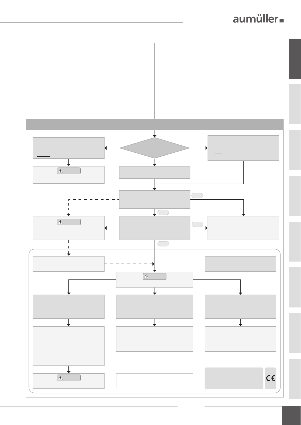
The following owchart can be applied, which also includes
the protective measures in accordance with EN 60335-2-
103/2016-05.
Hazard analysis according to DIN EN 60335-2-103
Contactless entrapment protection
(20.ZAA.8.1)
Passive infra-red and active light sensors
or
pressure mats
Contact-based entrapment protection
(20.ZAA.8.2)
Pressure-sensitive safety switch strips
or
Motor current monitoring systems
(internal and external)
Hold-to-run switch:
stops movement at HSK < 20 mm
at a closing force of > 150 N at HSK
(20.ZAA.5)
Operating element in
direct range of vision:
a.) Key switch or
b.) other switch,
then: installation > 1,5 m,
inaccessible for public
(7.12.1)
Keep people away during closing!
Caution
Protection devices
Caution
Using drives
NSHEV in accordance
with EN12101-2
without dual purpose for ventilation
NSHEV in accordance
with EN12101-2
with dual purpose for ventilation
(1.Z.109)
Natural ventilation
Installation height of drive and lower
edge of casement: > 2,5 m above oor
(ZAA.20.2)
Opening at HSK: < 200 mm and
Speed at HSK:
CLOSE <15 mm/s / OPEN < 50 mm/s
(20.ZAA.2)
Yes
Yes
No
No
No
risc assessment
required
Observe danger at NSK
< 2,5 m above oor!
Caution
Keep people away during closing!
Caution
In the environment with children /
people in need of protection
Information in parentheses refers
to the chapters of DIN EN 60335-2-103.
Declaration of Conformity
power operated window
+ CE label

6
Power supply NT-S-2 KS2 / KSA
01
Safety instructions
Crush and shear points
To avoid injuries, crushing and shear points between
casement and frame must be secured against entrapment
up to an installation height of 2,5 metres above the oor
with appropriate measures. This can be achieved e.g. by
using contact-based or contactless protective devices
against entrapment, which stop the motion through contact
or through interruption by a person. A warning symbol at
the opening element must indicate this clearly.
Routing cables and electrical connection
Electrical lines and connections may be routed or instal-
led only by approved specialist contractors. Never operate
drives, Control Units, operating elements and sensors at
operating voltages and connections contrary to the speci-
cations of the manufacturer.
wArNiNg
Area of application
The control device must be used only for its intended pur-
pose. For additional applications, consult the manufacturer
or its authorised dealer.
Installation
These instructions are intended for expert and safety-
conscious electricians and / or qualied personnel familiar
with the electrical and mechanical installation of drives and
control systems.
Mounting material
The required mounting material must be modied to t the
occurring load.
Safety instructions
It is important to follow these instruc-
tions for the safety of persons. These
instructions must be kept in a safe place
for the entire service life of the products.
Risk of crushing and entrapment!
Electric operated windows can close
automatically!
The compressive force is absolutely
sufcient to crush ngers in case of ca-
relessness.
The planning and calculation of the
wiring system is the responsibility of
the builder or its agent or the authori-
sed builder and must be performed
according to the statutory provisions.
NoTe
NoTe
All relevant instructions must be observed for the in-
stallation, specically:
• VDE 0100 Setting up high-voltage systems up to 1000 V
• VDE 0815 Wiring cables
• Specimen Guideline on Conduits German designation
(MLAR).
We recommend using exclusively sys-
tem components by Aumüller, because
their compatibility is carefully checked
in the factory. Aumüller shall not assume
liability for the system-compatible func-
tioning of third party components.
Applications and connections other than
explicitly described in these instructions
require the express written consent of
Aumüller. Utilization of applications and
components not expressly authorised by
Aumüller are considered as unintended
use even if their perfect functioning is
proven at commissioning (e.g. approval
under building law).

7
Power supply NT-S-2 KS2 / KSA
01
Safety instructions
The types of cable, cable lengths and cross-sections must
be selected in accordance with the manufacturer’s technical
data. If necessary, the cable types must be coordinated with
the competent local authorities and energy supply com-
panies. Low-voltage lines (24 V DC) must be routed
separate from the high-voltage lines. Flexible cables may
not be ush-mounted. Freely suspended cables must be
equipped with strain reliefs.
Clamping points must be checked for tightness of threa-
ded connections and cable ends. Access to junction boxes,
clamping points and external drive control systems must be
ensured for maintenance work.
Commissioning, operation and maintenance
After the installation and after each modication in the
set up all functions must be checked with a trial run.
After the installation of the system is completed the
end-user must be introduced to all important operating
steps. If necessary, he must be advised of all remaining risks /
dangers.
The end-user must be instructed in intended use of the
drives and, if necessary, the safety instructions.The end-user
must be specically instructed that no additional forces,
except for the pressure and tension in the opening and
closing direction of the casement, may be applied to the
spindle, chain or lever of the drive.
The power line on-site must be secured se-
parately and provided all poles separators.
After opening of the system housing voltage
carrying parts are exposed. The system must
be separated from the power supply and bat-
tery voltage before each intervention in the
Control Unit of the system.
Cables must be laid such way that they cannot
be sheared off, twisted or bent during operati-
on. It is recommended to perform an insulati-
on measurement of the system’s line network
and to document this.
wArNiNg
It is imperative that the information pro-
vided in the installation instructions of
the controlled window drives is observed
and obeyed!
NoTe Post warning signs!
During correct assembly of drives with mounting elements
at a window, and connection to an external Control Unit,
the interfaces resulting from the mechanical and electri-
cal performance characteristics of single elements must be
observed.
Other persons must be kept away from
the casement when a hold-to-run switch
(push button) is operated or when a
window, which has been opened by a
smoke and heat exhaust system, is clo-
sing!
The operating element of hold-to-run
switches must be installed within di-
rect view from the window, but isola-
ted from moving elements. If the switch
is not a key-operated switch it must be
installed at a minimum height of 1,5 m
and inaccessible to the public!
Do not allow children to play with
permanently mounted control devices
and keep remote controls out of reach of
children!
CAuTioN
CAuTioN
CAuTioN
Before working on the system, it must be com-
pletely disconnected from the power supply
and emergency power supply (e.g. batteries)
and secured against being switched on again
accidentally. While working in the Control
Unit the workplace must be secured to prevent
unauthorised access. You must ensure that
unauthorised personnel are unable to open
the Control Unit.
wArNiNg Check all functions of the system before
releasing it for operation.
The installation instructions of system components (smo-
ke detector, natural smoke and heat exhaust ventilators,
drives, etc.) are part of the documentation for the complete
system and must be kept accessible for authorised quali-
ed personnel, together with the installation and operating
instructions, for the entire service life of the system.
Replacement parts
System components are to be replaced only with spare
parts from the same manufacturer. Liability, warranty and
customer service are void if third-party parts are used. Only
original spare parts from the manufacturer are to be used
for expansions.
8
Power supply NT-S-2 KS2 / KSA
01
Safety instructions
Ambient conditions
The product may not be subjected to impacts or falls, or
to vibrations, moisture, aggressive vapours or other harmful
environments, unless the manufacturer has released it for
one or more of these environmental conditions.
• Operation:
Ambient temperature: -5 °C … +40°C
Relative humidity: < 90% up to 20°C;
< 50% up to 40°C;
no formation of condensation
• Transport / Storage:
Storage temperature: 0°C … +30°C
Relative humidity: < 60%
Accident prevention regulations and employer‘s
liability insurance guidelines
For work on or in a building or building part the provisi-
ons and instructions of the respective accident prevention
regulations (UVV and employer‘s liability insurance guide-
lines (BGR /ASR) must be observed and obeyed.
Declaration of Conformity
The control device is manufactured and inspected for
its intended use in accordance with the European guide-
lines. The relevant Declaration of Conformity is at hand.
If the use or operation of the control device or the con-
nected window drives deviate from this a risk assess-
ment must be performed for the complete powered
window system and a Declaration of Conformity according
to Machinery Directive 2006/42/EG issued as well as a
CE labeling obtained.
Guidelines and Standards
It is essential that the most recent versions of country-
specic laws, regulations, provisions and standards be ob-
served during installation and for electrical connections.
These are for instance:
State building code with special construction regulations
such as:
- Industrial construction guideline
- Venue regulations, etc.
MLAR - Sample Guideline on Conduits German desig-
nation
Provisions of the re protection authorities TAB
(technical connection conditions)
for Utility companies
German Regulations for Occupational Insurance Sche-
mes, such as:
- ASR A1.6 and 1.7(substitute for BGR 232)
Additional standards and guidelines, such as:
EN 60335-2-103 Safety of household and similar elec-
trical appliances
EN 60730-1 Automatic electrical controls
EN 12101-10 / prEN 12101-9 (ISO 21927-9/10)
Smoke and heat control systems
DIN 4102-12 Functional integrity of electric cable
systems
VDE 0100 Installation of high-voltage systems up
to 1000 V
VDE 0298 Use of cables
VDE 0815 Wiring cables (for telecommunication
and data processing systems)
VDE 0833 Alarm systems
VdS-Guidelines: 2593, 2581, 2580, 2592
Accident prevention regulations, in particular:
- VBG 1 „General rules“ and
- VBG 4 „Electrical systems and equipment“.
For placing on the market, installation and operation out-
side Germany, the relevant national laws, regulations,
standards and safety provisions apply.
The contractor is responsible for proper installation or
operation and the issue of a Declaration of Conformity
according to European guidelines.

9
Power supply NT-S-2 KS2 / KSA
Data sheet
02
2,0 A
Power supply NT-S-2 KSx
Power supply NT-S-2 KSx
Part.-No.: 680029
Operating voltage: 230 V AC (195 – 253 V AC, 50/60 Hz)
Rated power consumption: 30 W
Output voltage: 24 V DC (20 – 28 V DC / 2 Vpp)
Output current: 2,0 A
Outputs: 1x drive line
24 V DC / 2,0 A
Connections: 24 V DC drives, up to max. 2,0 A
Connection cable: non-halogen, grey 6 x 0,75 mm², length 3 meters
can be extended to a maximum of 25 meters
Housing: aluminum natural anodized, RAL9016
or optionally in other RAL colors
Dimensions (WxHxD): 41 x 26 x 215 mm
Connection terminals: screw terminals 1,0 mm² (rigid wire)
Protection rating: IP 32
Part.-No.: 680027
Operating voltage: 230 V AC (195 – 253 V AC, 50/60 Hz)
Rated power consumption: 30 W
Output voltage: 24 V DC (20 – 28 V DC / 2 Vpp)
Output current: 2,0 A
Outputs: 1x drive line
24 V DC / 2,0 A
1x continuous current
24 V DC / 0,2 A
Connections: 24 V DC drives, up to max. 2,0 A
24 V DC continuous current, up to max. 0,2 A
Connection cable: non-halogen, grey 6 x 0,75 mm², length 3 meters
can be extended to a maximum of 25 meters
Housing: aluminum natural anodized, RAL9016
or optionally in other RAL colors
Dimensions (WxHxD): 41 x 26 x 230 mm
Connection terminals: screw terminals 1,0 mm² (rigid wire)
Protection rating: IP 32
230 VAC
230
V
AC
Data sheet: Power supply NT-S-2 KS2/KSA - 230 V AC / 24 V DC
10
Power supply NT-S-2 KS2 / KSA
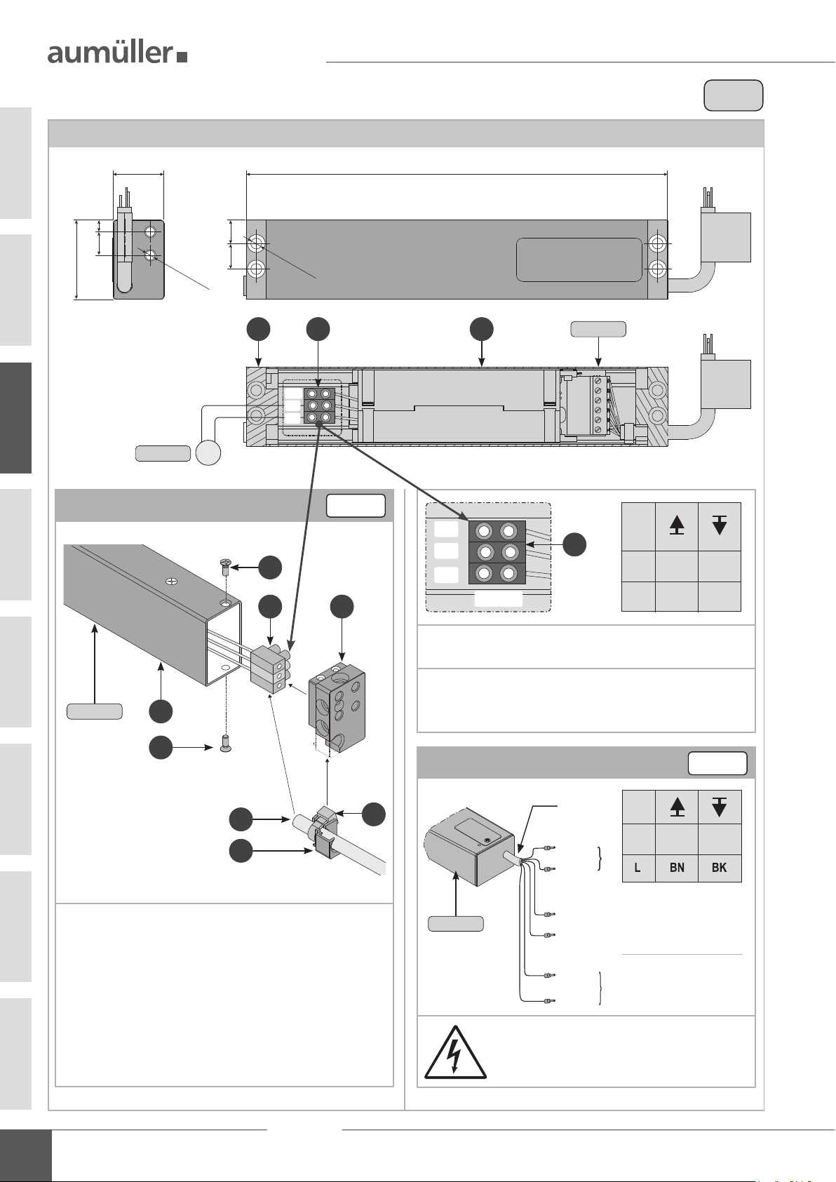
Power supply NT-S-2 KSx: 680029
Circuit Diagram
2,0 A
Circuit Diagram: Power supply NT-S-2 KS2/KSA - 230 V AC / 24 V DC
Connection assignment
Make sure when establishing the connection
that there is no voltage at the terminals!
Unused wires must be safely insulated!
M
215
WH
BN
BU
26
für M5
1213
6
41
12
für M6
230 V AC
230 V AC
AK
BK
WH
GN/YE = PE
GY
BN
BU = N
without function
(insulate cables safely)
for custom-made products
230V
680029
Connect the drive
Pull the terminal
out of the power supply housing
.
Connect the drive - using the connecting cable (not inclu-
ded in the scope of delivery) - to the terminal .
Mount connection cable in the cable entry - using cable
ties .
Plug in the terminal in the power supply .
Cable entry - with connection cable and cable ties -
push into the end cap .
Mount end cap with screws on the power supply
housing .
WH without function (insulate cables safely) for custom-
made products.
The running direction of the power supply may be changed
by interchanging (polarity reversal) the wires „BN - (brown)“
- „BU - (blue)“.
OPEN CLOSE
680029
680029
24V DC
BN +
+-
-
BU
4
5
5
7
2
3
1 6
7
24V
16
WH
BN
24V DC
BU
1
03
for M5
for M6
11
Power supply NT-S-2 KS2 / KSA
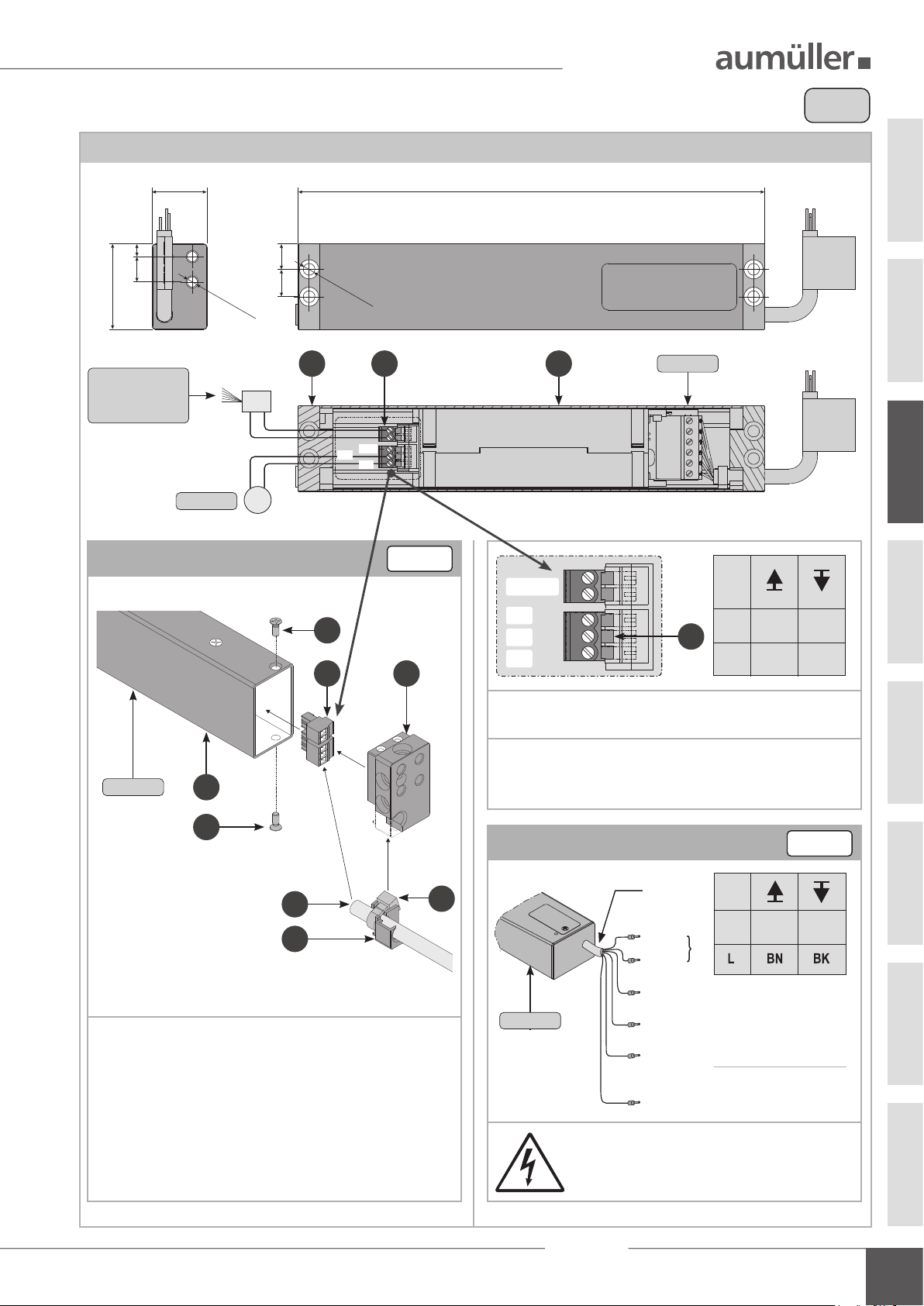
Power supply NT-S-2 KSx 680027
03
Circuit Diagram
2,0 A
Circuit Diagram: Power supply NT-S-2 KS2/KSA - 230 V AC / 24 V DC
Connection assignment
Make sure when establishing the connection
that there is no voltage at the terminals!
Unused wires must be safely insulated!
M
230
BU WH
BL
26
für M5
1213
6
41
12
für M6
230 V AC230 V AC
AK
BK
WH
GN/YE = PE
GY
BN
BU = N
= L
without function
(insulate cables safely)
for custom-made products
230V
680027
Connect the drive
Connect the drive - using the connecting cable (not inclu-
ded in the scope of delivery) - to the terminal .
Mount connection cable in the cable entry - using cable
ties .
Plug in the terminal in the power supply .
Cable entry - with connection cable and cable ties -
push into the end cap .
Mount end cap with screws on the power supply
housing .
WH without function (insulate cables safely) for custom-
made products.
The running direction of the power supply may be changed
by interchanging (polarity reversal) the wires „BN - (brown)“
- „BU - (blue)“.
OPEN CLOSE
680027
680027
24V DC
BN +
+-
-
BU
4
5
5
7
2
3
1 6
7
24V
16
WH
BU
24V DC
BL
1
continuous voltage
for at scan
(pinch protection)
for M5
for M6

12
Power supply NT-S-2 KS2 / KSA
04
13
Power supply NT-S-2 KS2 / KSA
04
Liability
We reserve the right to change or discontinue products at any time
without prior notice. Illustrations are subject to change.Although we take
every care to ensure accuracy, we cannot accept liability for the content
of this document.
Warranty and Customer serviceDemounting and dismantling
The Control Unit must be stored only in locations protected from mois-
ture, severe contamination and temperature uctuations (not above
30°C). The packaging must not be removed until the control system is to
be installed. Disconnect the batteries and store them separately after the
control device has already been in operation.
It is imperative that the following is observed for storage of the batte-
ries:
Before dismantling the Control Unit, isolate it comple-
tely from the mains!
If the Control Unit is permanently decommissioned the statutory provi-
sions for destruction, recycling and disposal must be observed. The con-
trol device contains plastic, metal, electrical components and batteries.
Replaced batteries contain highly toxic pollutants and may therefore only
be disposed of at collection points prescribed by the legislator.
Keep the storage time of lead-acid batteries short, be-
cause the batteries discharge as time passes. At the
latest after seven months in storage batteries must
be recharged. Use either a suitable battery charger or
connect the batteries to an EMB Control Unit and sup-
ply same with mains voltage. In both cases, charging
requires a minimum of 8 hours (depending on the
discharge state).
In principle, our:
„General Terms for the Supply of Products and Services of the Electri-
cal Industry (ZVEI)“.
„Terms for the used software“.
The warranty is compliant with legal provisions and applies to the
country in which the product has been acquired.
The warranty includes material and manufacturing defects incurred
during normal use.
The warranty period for delivered material is twelve months.
Warranty and liability claims for personal injuries or tangible damages
are excluded, if caused by one or more of the following:
• Improper use of the product.
• Improper installation, commissioning, operation, maintenance or
repair of the product.
• Operating the product, if installed defectively or incorrectly, or with
its safety and protection devices not working .
• Ignoring instructions and installation requirements in these in-
structions.
• Unauthorised constructional modications the product or accessories.
• Disaster situations due to the effects of foreign bodies and force
majeure.
• Wear and tear.
Point of contact for possible warranty claims or for repair parts or acces-
sories is the responsible branch ofce or the responsible person at
.
Contact data are available at our homepage
(www.aumueller-gmbh.de)
Disposal
The symbol of the „crossed-out dustbin“ means that you are legally
obliged to collect these appliances separately and recycle them in an
environmentally friendly manner. Do not throw old electrical appliances
into the household waste! Information on return options can be found at:
https://www.aumueller-gmbh.de/umweltschutz
Before disposing of old electronic devices, please delete all personal data
stored on them, if available. Remove any device batteries or rechargeable
batteries and put them in the old battery collection. Tape the poles be-
forehand to avoid a short circuit.
Dispose of the shipping and transport material, separated according to
material, in the appropriate recycling bin.
Disposal / Warranty

14
Power supply NT-S-2 KS2 / KSA
05

15
Power supply NT-S-2 KS2 / KSA
05
Translation of the original instructions (German)
Important note:
We are aware of our responsibility, which is why we present life-supporting and value-preserving products with greatest possible conscientiousness. Although we
make every effort to ensure that the data and information are as correct and up-to-date as possible, we still cannot guarantee that they are free from mistakes and
errors.
All information and data contained in this document are subject to alterations without prior notice. Distribution and reproduction of this document as well as the
use and disclosure of its content is not authorized unless expressly approved. Offenders will be held liable for the payment of damages. All rights reserved in the
case of a patent award or utility model registration.
Basically the General Terms and Conditions of
Aumüller
AuTOmATIC
GmbH apply to all offers, supplies and services.
The publication of these assembly and commissioning instructions supersedes all previous editions.
Certi cate and Declaration
of Conformity
We declare under our sole responsibility that the product
described under "Data sheet" is in conformity with the
following directives:
• 2014/30/EU
Directive relating to Electro-Magnetic Compatibility
• 2014/35/EU
Low voltage Directive
We further declare that the drive is an incomplete
machine within the meaning of the European Machinery
Directive (2006/45/EG).
Technical le and declaration at rm:
Aumüller
AumATIC
GmbH
Gemeindewald 11
D-86672 Thierhaupten
Ramona Meinzer
Managing Director (Chairman)
The proof of the application of a quality management
system is for company:
Aumüller
AumATIC
GmbH
according to the certication basis DIN EN 9001 as well
the "Declaration of Incorporation and Conformity" can
be accessed via the QR code or directly on our homepage:
(www.aumueller-gmbh.de)
Note:
Certikate and Declaration
9000021551_V2.0_KW 37.2023
This manual suits for next models
3
Table of contents


