HPSG2H-12V5A-C
Table 6. Operating parameters.
Environmental class EN 50131-6
Environmental class EN 60839-11-2
20%...90%, without condensation
Vibrations during operation
Impulse waves during operation
Vibrations and impulse waves during transport
According to PN-83/T-42106
2. Installation.
2.1 Requirements.
Buffer power supply is designed to be installed only by qualified installer with necessary permits and
authorisations (required in installation country) to connect (interfere) with the ~230 V mains supply. Unit should be
mounted in confined spaces, in accordance, with normal relative humidity (RH=90% maximum, without condensing) and
temperature from -10°C to +40°C.
Device must be mounted in a vertical position with cable glands facing downwards. Mounting in any other
position is not permitted. Ensure free convective airflow around enclosure. In order to meet the EU requirements, follow
the guidelines on: power supply, enclosures and shielding: - according to application.
Because the power supply is designed for the continuous operation and is not equipped with ON/OFF switch, the
power supply circuit should have the appropriate overload protection. Moreover, the user shall be informed about the
method of unplugging (most frequently through separating and assigning an appropriate fuse in the fuse-box).
The electrical system shall follow valid standards and regulations.
2.2 Installation procedure.
CAUTION!
Before installation, cut off voltage in 230 V power-supply circuit. To switch power off, use an
external switch, in which distance between contacts of all poles in disconnection state is not
less than 3mm.
It is required to install in the supply circuits, in addition to power supply, circuit breaker with 6 A
nominal current.
1. Mount device and feed connection wires through glands and filler inserts. Then tighten the glands (unused
ones should be blanked off).
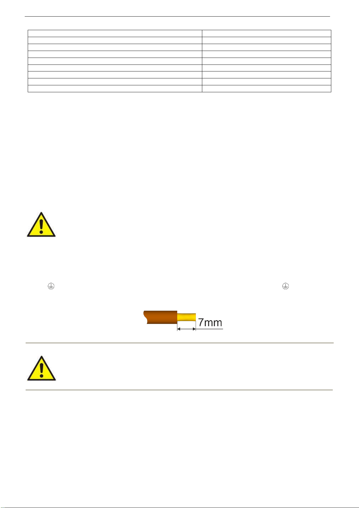
2. Connect power cables (~230 V) to L-N clips of PSU. Connect ground wire to clip marked by earth symbol
. Use a three-core cable (with a yellow and green protection wire) to make connection ). Lead the
power cables to the relevant terminals of the power supply via an isolation conduit. Wires should be
deisolated to a length of 7mm.
The shock protection circuit shall be done with a particular care: the yellow and green
wire coat of the power cable should be connected to the terminal marked with the grounding
symbol on the PSU enclosure. Operation of the PSU without the properly made and fully
operational shock protection circuit is UNACCEPTABLE! It can cause damage to the
equipment or an electric shock
3. If needed, connect the device cables to the technical outputs:
- EPS; technical output of AC network absence indication
- APS; technical output indicating battery failure
4. Connect equipment to the appropriate output terminals of power supply (positive connector +V, negative
connector -V).
5. Use the IBAT jumper to set the maximum battery charging current, taking into account charging capacity and
required charging time.
6. Mount the battery in the battery compartment of the enclosure. Mount the battery in the battery compartment of
the enclosure. Connect the batteries with the PSU paying special attention to the correct polarity and type of
connections.
7. Switch on ~230 V supply. LEDs on the PCB of power supply should light.
Output voltage of the PSU, without load U = 13,8 V DC.
During battery charge, voltage can amount to U = 11 - 13,8 V DC.