Aumuller 524178 Installation and operation manual
Parameterisation-Interface
Feature / Equipment:
Power supply 24 V DC is not
included in the scope of delivery!
Strictly observe the information given
in this and in the instructions for instal-
lation of the drives when parameterize
the Aumüller drives with the Paramete-
risation-Interface and DCT.
Details can be found on our website
www.aumueller-gmbh.de
Keep these instructions for the entire
service life of the product.
• The Parameterisation-Interface serves as a
hardware interface for the parameterisation of
Aumüller drives.
• In conjunction with the Aumüller DCT software
- and the Drives Plug-In available in it - a wide
variety of drive parameters can be individually
congured.
• Can be used for all drives with control type S12
and S3.
Warranty claims require proper and
professional assembly, installation and
maintenance in accordance with the
statutory regulations and the specica-
tions of the manufacturer of the drives.
The safety instructions in the supplied
product documentation must be obser-
ved.
Power supply 24 V DC is not included in
the scope of delivery!
The 24 V DC power supply of a Control
Unit or the Test kit (Part.-No.: 533984)
can be used!
Note
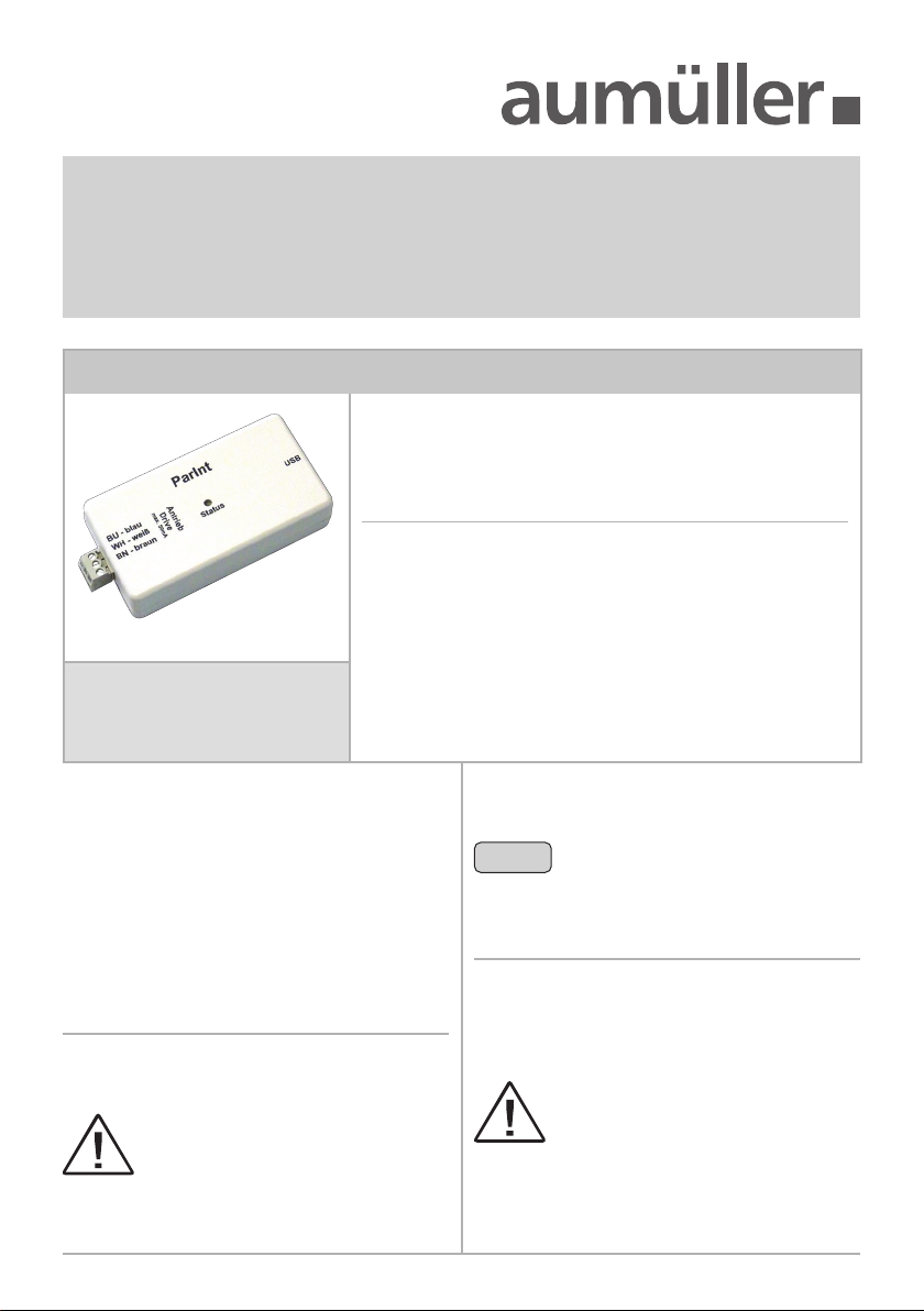
Parameterisation-Interface
Part.-No.: 524178
Application: Hardware interface for parameterisation of
Aumüller drives with the Aumüller software
DCT.
Rated voltage: 24 V DC +/-20 %
Congurable 24 V DC in version S12, S3
drives: 230 V AC in version S12
Connections: 3x Pluggable screw terminals 1,0 mm²
1x USB port
Scope of delivery: 1x Interface
1x USB cable
1x Connection cable
2Installation instructions: DCT
System requirements for DCT:
Direct Conguration Tool
InstallatIon step 1:
Install DCT software
The programme can be installed on a computer with
at least the following characteristics:
CPU:
1 GHz or higher
Operating systems:
Microsoft® Windows 10 64bit or higher
MacOS 13 Ventura or higher
Memory:
Min. 1 GB RAM
Hard disk:
At least 200 MB free memory space
Accessories:
USB connection for connection between
computer and control unit, internet connection
for system installation and updates
Download DCT software:
https://www.aumueller-gmbh.de/downloads/
software/
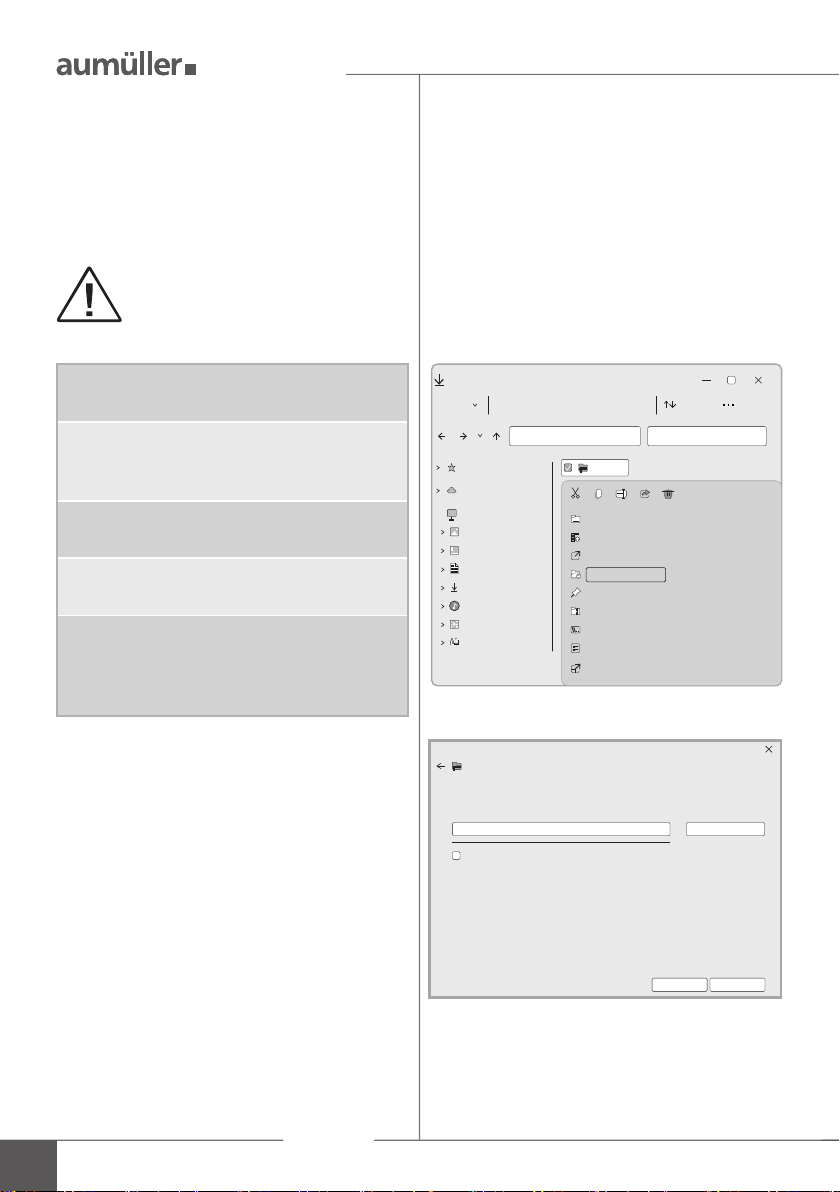
Unpack the archive to the desired destination.
The DCT software is designed exclu-
sively for the parameterisation of the
Aumüller drives indicated in these in-
struction.
Show extracted files when complete
Browse ...
Extract Cancel
Extract Compressed (Zipped) Folders
Select a Destination and Extract Files
Files will be extracted to this folder:
C:\User\User\Downloads\dct
Downloads
New Sort
Quick access
OneDrive-Personal
This PC
Pictures
Desktop
Documents
Downloads
Music
Videos
Local Disk (C:)
dct.zip
Open Enter
Alt+Enter
Shift+F10
Open with
Open in new window
Extract all ...
Pin to "Start"
Compress to ZIP file
Copy as path
Properties
Show more options
Setting up

3
Installation instructions: DCT
InstallatIon step 2a:
Connection of drives 24 V DC with
S12 or S3 electronics
InstallatIon step 2b:
Connection of drives 230 V AC
with S12-electronics
Connect computer, Parameterisation-Interface
and drives.
Connect computer, Parameterisation-Interface
and drives.
Colour DIN IEC 757
BK = black GN /YE = green / yellow
BN = brown GY = grey
BU = blue WH = white
BU
BN
BU
BN BN
WH
BU
DCT
BU
BN
S12
S3
24VDC
24VDC
If only one drive is parameterised, an
additional power supply is not neces-
sary.
During the parameterisation: Do not
switch off the operating voltage when
connected to a control unit, because it
could lead to complications.
Note
WH
BN
GY
WH
BU
DCT
BU
BN
S12
230VAC
BK
BU
GN / YE
PE
N
L
230 V AC
Connection
Note polarity!
24 V DC from control
unit (direction CLO-
SED) or from
24 V DC power supply
unit
Interface
Drive
Drive
Interface

4Installation instructions: DCT
Multi-drive operating (set)
For drives in multiple operation (set), a second
cable leads already routed out of the end cap.
This cable can be used for conguration with DCT.
InstallatIon step 2c: Connection of drives 230 V AC with S12 -
parameterisation on the 24 V-side
Only one drive can be congured at a
time. Separate the two drives.
Do not use an external power supply,
otherwise the drive will be destroyed.
Program without voltage.
Only connect to the Parameterisation-
Interface.
285 285
Connection
connection box
site-supplied
24 V DC, non-halogen
approx. 3 m, 3 x 0,5 mm2
230 V AC, non-halogen
approx. 3 m, 6 x 0,75 mm2

5
Installation instructions: DCT
BU
WH
BN
DCT
BU
BN
S12
24VDC
Loosen the screws (drive type KS2).
Remove the end cap
from the drive hou-
sing .
Pull out the cable , strip the insulation and
connect it to the Parameterisation-Interface.
After conguring the drives, insulate the cab-
le .
Mount the end cap
with screws at the
drive housing .
3
1
4
1 2
At 230 V AC drives (type KS2 / KSA) with Z version
use the internal cable on the 24V-side:
Connection of drives 230 V AC with S12 -
parameterisation on the 24 V-side
Do not use an external power supply,
otherwise the drive will be destroyed.
Program without voltage.
Only connect to the Parameterisation-
Interface.
Connect computer, Parameterisation-Interface
and drives.
Interface
Connection
24 V DC side
230 V AC side

6Installation instructions: DCT
InstallatIon step 3: Start conguration
The LED of the Interfaces ashes red. The
Plugin Drives is searching for connected drives.
Once the drives have been detected, congura-
tion can begin.
BU
WH
BN BU
BN
UniPC
S12
230VAC
Start DCT.exe in the unpacked directory.
Download Drives Plug-In at the rst start.
Start the Plug-In to start the conguration.
At every regular start, DCT checks whether the-
re are updates for Drives and then automatical-
ly offers them for download.
Notes and descriptions of the individu-
al functions can be displayed by simply
hovering the mouse pointer over the
respective function (no click necessary).
Note
DCT.exe
DRIVES
DRIVES
DRIVES
Conguration
Interface
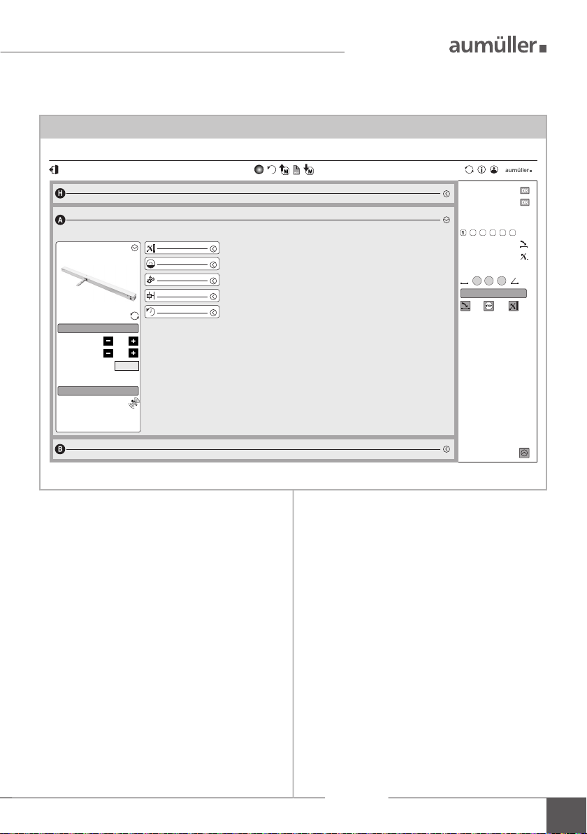
7
Installation instructions: DCT
Drives Plug-In
Determine position closed
With these drive commands, the
delay in Up is ignored.
Release control
Lock retriggering
Current direction
Device status
Address allocation
Found devices
Release group locking drive
Release group A
S/N drive:
Devices in group
0 devices
KS4 (S12)
1
Release group B
Device address
Release control
Diagnosis
yes
Number of devices
Invert direction
load static values
Factory reset
0 devices
The more data is fetched,
the longer the loading times are
Configuration of compound devices
Stroke
Force
Signal relay
Delays
Speed
Conguration

9000015401_V3.0_KW 32.2023
Table of contents


