ONTRAK ADU200 User manual

ADU200 USB Relay I/O Interface
User Manual
Ver 2.0
www.ontrak.net

Page 2 of 17 ADU200 User Manual
EU Declaration of Conformity
We, the undersigned,
Manufacturer:
Ontrak Control Systems Inc.
Address, City
1545 Maley Drive, Unit 3, Sudbury
Province, Country, Postal Code
Ontario CANADA P3A 4R7
Phone and FAX
(705) 671-2652 (705) 671-6127 ( FAX)
Email Address
certify and declare under our sole responsibility that the following Apparatus:
Model No: ADU200
SN: A00001 and higher
Description:
USB Relay I/O Interface
Brand:
Ontrak Control Systems Inc.
Conforms with the essential requirements of the EMC Directive 2004/108/EC, via Annex II, based on
the following specifications applied:
RF Emissions
EN55011:2009/A1:2010 Class B
ESD Immunity
IEC 61000-4-2:2008 Level 2 Criterion B
RF Immunity
IEC 61000-4-3:2006 +A1:2007 +A2:2010 Level 2 Criterion B
Safety
EN60950-1 2nd Edition (CSA/UL )
And therefore complies with the essential requirements and provisions of the EMC directive.
The technical documentation is kept at the following address:
Company:
Ontrak Control Systems Inc.
Address, City
1545 Maley Drive, Unit 3, Sudbury
Country, Postal Code
Ontario CANADA P3A 4R7
Phone Number
(705) 671-2652
Fax, Email
Name of Person binding the
manufacturer.
Tom Fortin- Director
Ontrak Control Systems Inc
January 10, 2018
Sudbury , Ontario, CANADA

Page 3 of 17 ADU200 User Manual
Table Of Contents
1. What is Included and Where to Start 4
2. ADU200 Features 4
3. The ADU200 STATUS LED 5
4. AduHidTest USB Device Test Program 6
5. ADU200 Command Summary 10
6. ADU200 Command Descriptions 11
6a) Relay Commands 11
6b) Digital Input Commands 12
6c) Event Counter Commands 14
6d) Watchdog Timer Commands 15
7. Specifications 16
8. Dimensions 17

Page 4 of 17 ADU200 User Manual
1. What is Included and Where to Start
The ADU200 ships complete with a 10' USB cable, and this User Manual.
A complete Windows SDK including DLL, programming language examples (MatLab, LabView, Visual C, Visual Basic,
.NET, Linux, Python, OSX etc.), and our AduHidtest software is available at:
www.ontrak.net/programming.htm
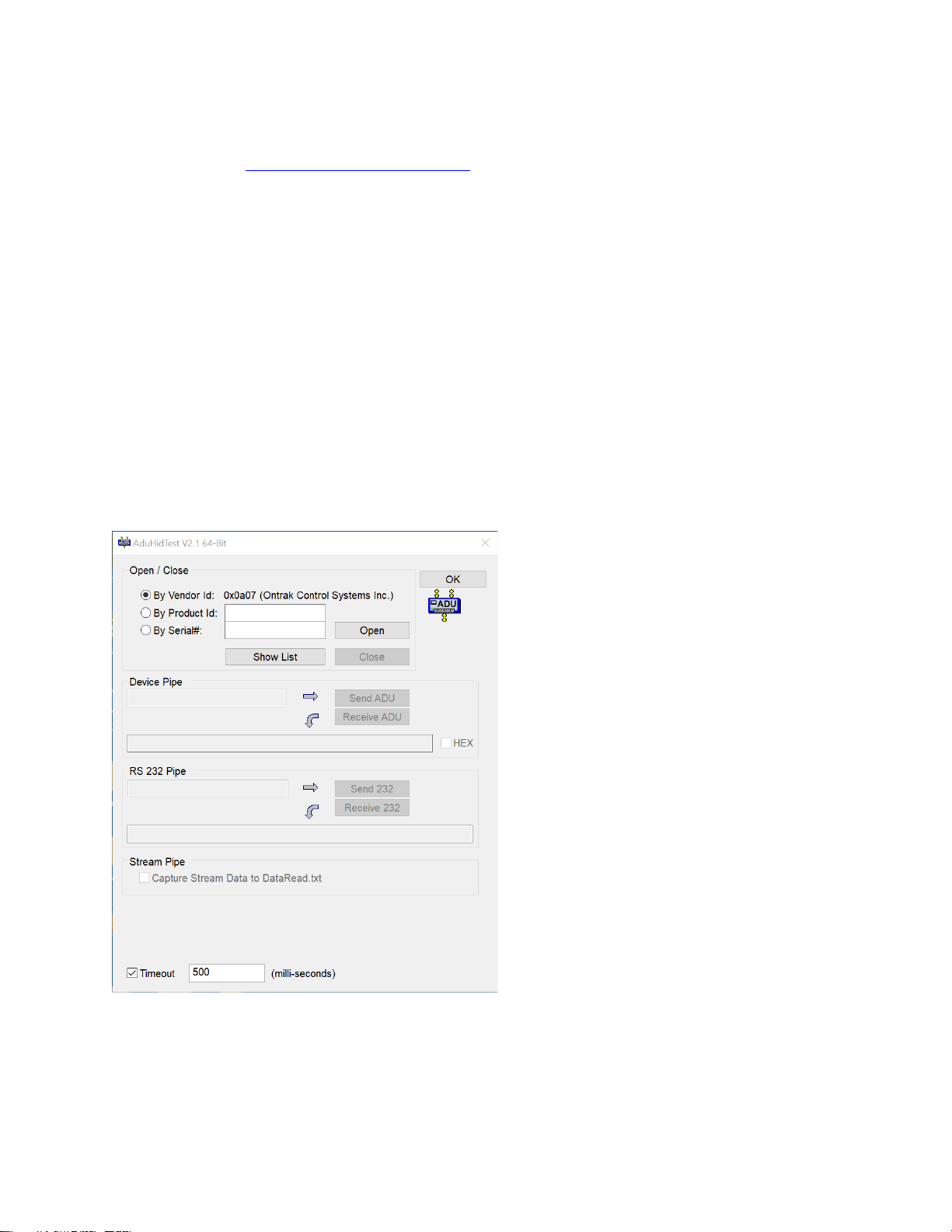
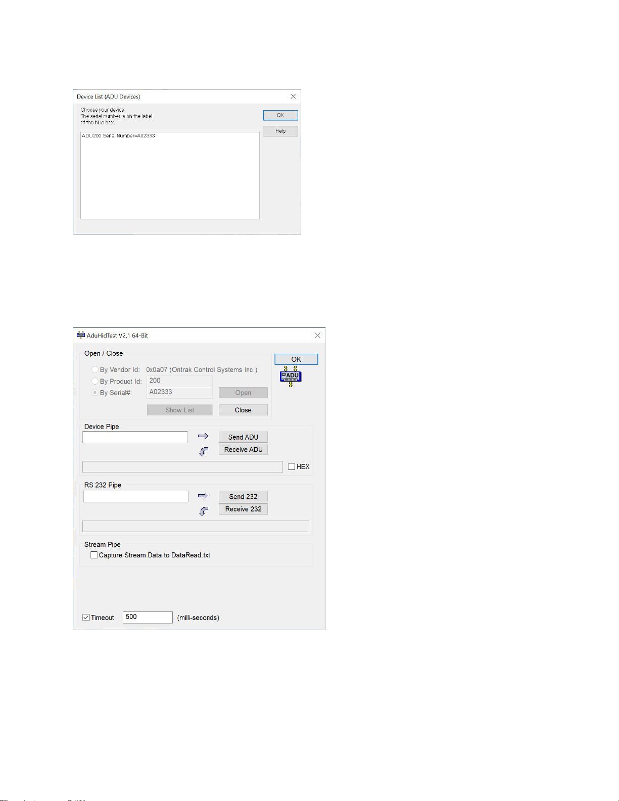
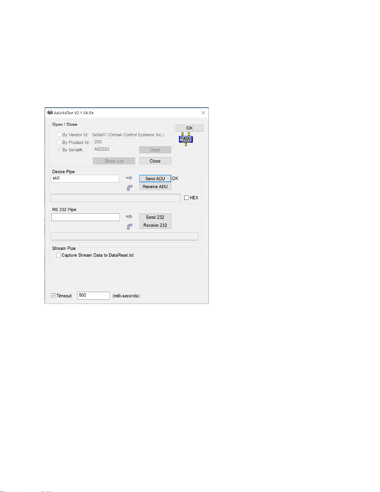
First time users should first review the ASCII command set for the ADU200 and then use AduHidTest USB test
software to become familiar with the command syntax, and the operation of the various features of the product.
Note: The AduHid DLL requires one of the following Windows operating systems, Windows XP, Windows 7, 8, 10 or
higher. The programming section of the website also contains examples for use with various other operating
systems, and provides details that allow use of the ADU200 without using the Windows based AduHid DLL.
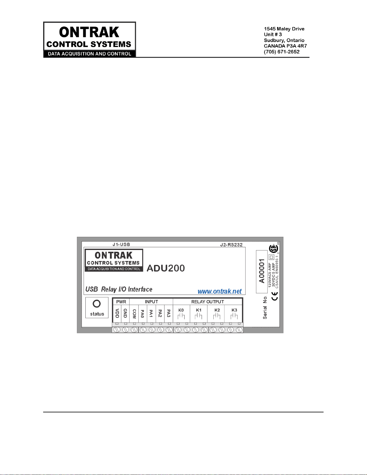
2. ADU200 Features
•Bus Powered, no external power supply required.
•Uses high quality Panasonic APAN3105 relays.
•4, N. O. Mechanical Relay outputs rated 5.0A @ 120VAC, 5.0A @ 30VDC
•4 Digital inputs suitable for contact or TTL Input, also accept up to 24VDC
•4, 16-bit event counters associated with digital Inputs.
•CSA/UL Certified, CE Marked
•High Retention USB connector.
•Bi-colour LED status indicator.
•High quality cage-clamp type terminal blocks.
•Uses standard HID drivers included with Windows 7,8,10 or higher.
•Mini-driver (DLL) provided for use with Windows based software including LabVIEW and MatLab.
•Programming examples and sample code available for VB, VB.NET, Visual C, Python and others.
•Meets IEC61000-4-2 ESD protection for USB port.
•Available as standard DESKTOP mount, or optional FLANGE, DIN RAIL, or VELCRO mount.

Page 5 of 17 ADU200 User Manual
3. The ADU200 STATUS LED
The ADU200 STATUS LED is a bi-colour (Red/Green) led indicator used to identify the status of the ADU200 USB
connection.
The LED modes are;
RED -ADU200 powered but not enumerated.
GREEN -ADU200 powered and enumerated by host computer.
OFF -ADU200 disconnected from USB bus.
The ADU200 can be connected to the USB bus via the enclosed 10' A-B USB cable. The cable provides both power
and communications connections to the ADU200. When first connected, the STATUS led will turn RED indicating
power is applied. For Windows operating systems, a message may flash on the screen indicating;
New hardware Found
ADU200 USB Relay I/O Interface
Depending on the version of Windows, the host may prompt to search for a driver. Select,
Let Windows Search for a Driver
and click next.
After several seconds, the STATUS led will turn green indicating enumeration is complete. The enumeration
process is completely transparent to the application program as the ADU200 is a low-speed USB HID class device.
Enumeration is completed by the Windows (or other) operating system using standard USB HID drivers.
The ADU200 can be connected directly to the host hub or externally powered hubs.
Caution: (Use of System Sleep): If the operating system allows the host computer to
enter sleep mode, attached USB devices will be set to suspend mode. In suspend mode
the ADU200 relay outputs remain in their last state. Ensure system power settings are
set such that the host computer does not enter sleep mode during normal operation.
Caution: If the operating system USB Selective Suspend is enabled, after the ADU200 is
physically connected and enumerated (LED Green), the host may suspend the
connection if no handle is opened to the ADU200. In suspend mode the ADU200 relay
outputs remain in their last state.

Page 6 of 17 ADU200 User Manual
4. AduHidTest USB Device Test Program
AduHidTest is a Windows based USB device test program used to test the connection of ADU data acquisition
devices to a USB port. The program is also a useful tool to allow programmers to become familiar with the ADU200
command set before programming in other languages. AduHidTest software can be downloaded from the
Ontrak website at: www.ontrak.net/programming.htm . Note that the program requires the AduHid.dll to
operate and it should be copied to the same directory as the AduHidTest.exe file.
There are three steps in using a USB device in any application software. The three steps are;
1. Obtain a handle for the USB device.
2. Send commands to the USB device.
3. Receive data from the USB device.
STEP 1: Obtain a handle for the ADU200
A handle is a unique code that application software uses to identify a USB device for the purpose of reading and
writing to the device. A USB bus can have up to 128 devices connected to a single host and there are three
criteria that can be used to open a handle. The three criteria are, Vendor ID, Product ID and Serial Number. If a
single device is connected to the bus, any of the three criteria may be used. If multiple devices are connected, we
recommend using the Serial Number to open the handle.
(All ADU devices have their unique serial number printed on the top label.)
Figure1 shows the AduHidTest software opening window.
Figure 1: AduHidTest Software Window

Page 7 of 17 ADU200 User Manual
The Open/Close section of the window is where the handle is determined. Click on the Show List button to view
the devices connected to the USB bus. (Note: Only ADU devices will be listed ) Figure 2 is the window that appears
when the Show List Button is clicked.
Figure 2: ShowList Window
The window indicates that there is one ADU200 connected with serial number A02333. Select the device by double
clicking on the text “ADU200 Serial Number = A02333”. The AduHidTest main window will now display the product
ID and Serial number. Click the By Serial # radio button and then click Open to open the handle to the selected
ADU200. Figure 3 shows the AduHidTest window with the handle open to the ADU200.
Figure 3: Handle Open to ADU200

Page 8 of 17 ADU200 User Manual
STEP 2: Sending Commands to the ADU200
Once connected, you may now send commands to the available "pipes" on the ADU200 device. Pipes are the
individual connections to functional sections of the ADU200. The Device Pipe is used to send standard ASCII ADU
commands to control the peripherals built into the ADU200. The ADU200 does not use the Stream pipe. Type
"SK0" (set relay K0) into the device pipe send window and click Send ADU. An OK will appear beside the Send ADU
button if successful, as shown in Figure 4, and the ADU200 relay K0 will close. Note that ADU commands are not
case sensitive.
Figure 4: Sending "SK0" Command

Page 9 of 17 ADU200 User Manual
STEP 3: Receiving Data from the ADU200
Some commands cause a response to be sent from the ADU200 back to the host computer. For example, if an
"RE3" (read event counter on PA3) command is sent, the ADU200 will send back the value of the event counter. To
read responsive commands, simply click the Receive ADU button and the data will be displayed.
Figure 5: Sending "RE3" Command
Figure 6: Receiving Data
The received data indicates Event counter 3 is at 115 counts. These procedures can be repeated using the various
commands available on the ADU200. The AduHidTest software is an invaluable tool to allow programmers to
become familiar with ADU commands before programming in various other languages and/or operating systems.

Page 10 of 17 ADU200 User Manual
5. ADU200 Command Summary
Relay Commands (PORT K)
SKn Sets relay specified by n (n = 0 to 3)
RKn Resets relay specified by n (n = 0 to 3)
MKdd Sets PORT K to decimal value dd (dd=00 to 15)
SPKxxxx Sets PORT K to binary value xxxx. (x=1 or 0)
RPK Returns status of PORT K in binary format.
RPKn Returns value of relay specified by n. (n = 0 to 3)
PK Returns value of PORT K in decimal format.
Digital Input Commands (PORT A)
RPAn Returns status of input line in PORT A specified by n (n= 0, 1, 2 or 3)
RPA Returns status of PORT A in binary format.
PA Returns status of PORT A in decimal format.
Event Counter Commands (PORT A)
REnReturns present count of event counter (n = 0 - 3)
RCn Returns present count and clears event counter (n = 0 - 3)
DBn Sets de-bounce time of event counters (n=0, 1 or 2)
(0 =10ms, 1 = 1ms, 2 = 100us)
DB Returns present de-bounce setting.
Watchdog Commands
WDn Sets watchdog timeout length. (n=0, 1, 2 or 3)
(0=WD OFF, 1=1s, 2=10s, 3=1min)
WD Returns watchdog setting.

Page 11 of 17 ADU200 User Manual
6. ADU200 Command Descriptions
6a) Relay Commands (PORT K)
The ADU200 interface feature four relay outputs. They are configured as PORT K with individual assignments of K0
thru K3. The relay contacts have no polarity requirements and switch either AC or DC loads.
SKn Sets relay specified by n (n = 0 to 3)
Ex.
SK3 Closes relay K3
RKn Resets relay specified by n (n = 0 to 3)
Ex.
RK2 Opens relay K2
MKdd Sets PORT K to value dd (dd = 00 to 15)
Ex.
MK15 Turns on all relays
SPKxxxx Sets PORT K to value xxxx (x = 0 or 1))
Ex.
SPK0000 Opens all relays
RPK Returns status of PORT K in binary format.
Ex.
RPK
1100 Response (K3 and K2 are closed, K1 and K0 are open)
RPKn Returns value of relay specified by n. (n = 0 to 7)
Ex.
RPK0 Returns value of relay K0
0 Response (relay K0 is OPEN)

Page 12 of 17 ADU200 User Manual
PK Returns value of PORTK in decimal format.
Response is 3 bytes (000 to 255 in decimal)
Ex.
PK
128 Response (K7 is closed (SET), K0-K6 are open (RESET)
6b) Digital Input Commands (PORT A)
The ADU200 interface contains one 4-bit input port PORTA, labelled PA0 to PA3. PORTA is isolated from all other
external connections using opto-isolators with better than 2500V isolation. The COM connection is for connection
of input device voltage common. Input devices can be connected using external DC voltages of up to 28V. The VDD
output terminals provide a nominal 5VDC output that can be used as a supply to “wet” dry contact inputs
(switches, pushbuttons etc.) to the digital inputs. When using the internal VDD supply to connect dry contact
inputs, GND must be connected to COM to allow a return path for input current. Figure 6A shows how dry contacts
can be connected using the ADU200 internal supply. Note that GND is connected to COM.
CAUTION: VDD and GND connections are
not isolated from the USB supply. Use to
“wet” dry contacts only.
Figure 6A: Dry Contact Connections Using Internal VDD Supply.

Page 13 of 17 ADU200 User Manual
Figure 6B demonstrates the connection of dry contact inputs using an external DC supply. Note that the common
of the external supply is connected to COM, and the inputs used in this example are PA0 and PA1.
CAUTION: When using an external supply
with input devices make NO connection to
VDD or GND terminals.
Figure 6B: Dry Contact Connections Using External Supply
The digital input port commands are:
RPAn Returns status of input line in PORT A specified by n (n= 0, 1, 2 or 3)
Ex.
RPA2
1 Response (PA2 is high)
RPAReturns status of PORT A in binary format.
Response is 4 bytes (0000 to 1111 binary) (order is MSB-LSB)
Ex.
RPA
0100 Response (PA2 is High, PA0, PA1 and PA3 are Low)
PA Returns status of PORT A in decimal format.
Response is 2 bytes (00 to 15 in decimal)
Ex.
PA
15 Response (All lines of PORTA are High)

Page 14 of 17 ADU200 User Manual
6c) Event Counter Commands
Each digital input line of PORT A has an event counter associated with it. The event counters count low to high
transitions and are stored in a 16-bit counter that can be read, or, read and cleared. The event counters are
numbered 0 to 3 and count from 00000 to 65535 followed by a rollover to 00000. Table 1 identifies the event
counter port assignments.
Table 1: Event Counter Port Assignments
The event counters are read using either the RE command, or the RC command if the counter is to be cleared
following the read.
REx Returns present count of event counter (x = 0, 1, 2 or 3)
Response 5 bytes (00000 to 65535 in decimal)
Ex.
RE1
00023 Response (PA1 has seen 23 low to high transitions)
RCx Returns present count and clears event counter (x = 0, 1, 2 or 3)
Response 5 bytes (00000 to 65535 in decimal)
Ex.
RC3
00156 Response (PA3 has seen 156 low to high transitions, event counter 3 is cleared)

Page 15 of 17 ADU200 User Manual
6c) Event Counter Commands (continued)
The de-bounce time of the event counters can be set from 100us to 10ms (DEFAULT = 1 ms) using the DB
command as outlined below;
DBn Sets de-bounce time of event counters (n=0, 1 or 2)
(0 =10ms, 1 = 1ms (Default), 2 = 100us)
Ex.
DB0 De-bounce is set to 10ms
DB Returns present de-bounce setting.
Ex.
DB
0 Response (De-bounce is currently set to 10ms)
6d) Watchdog Commands
The ADU200 features a host watchdog function. The host watchdog, when enabled, resets all relays, and resets the
watchdog setting to 0 (WD OFF), when a watchdog timeout occurs. Following the enabling of the watchdog timer,
commands must be continuously received by the ADU200 within the selected timer interval or a watchdog timeout
will occur. After a watchdog timeout occurs, the watchdog setting must be reloaded. The host application should
poll the watchdog setting to determine if a watchdog timeout has occurred. Note that the watchdog timer is reset
when any command is received by the ADU200. This includes invalid commands.
WDn Sets watchdog timeout length.
(0=WD OFF, 1=1s, 2=10s, 3=1min)
Ex.
WD2 Sets the watchdog timeout to 10 seconds and enables watchdog timer.
WD Returns watchdog setting.
Ex.
WD
3 Response (WD timeout setting is 1 minute)

Page 16 of 17 ADU200 User Manual
7. Specifications
ADU200
Supply Voltage
NONE (Bus Powered)
USB Supply Current (relays de-
energized)
USB Supply Current (all relays
energized)
20mA Typical
95mA Typical
USB Connection Type
Low -Speed USB 1.1 HID
Operating Temperature
-25C to 85C Max
Isolation Voltage
2500Vrms
Digital Inputs ( 4 )
Vin HIGH (MAX)
28 VDC
Vin HIGH (MIN)
2 VDC
Vin LOW(MAX)
0.7 VDC
Vin LOW (MIN)
0 VDC
Input Z
2700 ohms
Event Counters (4)
Resolution
16 Bits
Input Type
Contact, TTL, Voltage up to 28VDC
Max Frequency
1KHz
Input Z
2700 ohms
Programmable Debounce
10ms, 1ms, or 100us
Relay Outputs (4)
Type
A (N.O.) Mechanical
AC Ratings
5Amps@120VAC
DC Ratings
5Amps@30VDC
On-State Resistance Typical
30mOhm (Initial)
Relay Used
Panasonic APAN3105
Maximum Recommended
Operating Speed
10 CPS
Safety Approvals
CSA/UL EN60950-1 2nd Edition
Mounting Options
Desktop (STANDARD), Flange Mount, DIN Rail, Velcro
Table of contents
Other ONTRAK Recording Equipment manuals