Bespoke BP-C9WY-6973-U User manual

BESPOKE POWER
5/3/22 Rev01 Visit our website for the latest documentation https://bespokepower.com
BP-C9WY-6973-U Installation Guide
Congratulations on your purchase of your new state-of-the-art taillight sequencer. This
sequencer is a universal fit for any vehicle with 2-3 taillights for each side of the vehicle.
What’s in the Box:
1. 1 –BP-C9WY-6973-U with color coded connectors
2. Mating cables with flying leads
3. 6 - Wire splices
4. 3 –sheet metal screws
Tools Required
1. Small bladed screwdriver (for any adjustments)
2. Needle nose pliers
3. Regular pliers for wire splices
4. Wire cutters
5. Drill w/1/8” bit
Installation
Part 1 - Mounting the Unit
1. Find a suitable location for mounting the sequencer housing at the rear of the vehicle. The ideal
location will adequately support the housing and not be subject to water spray. Mounting is not
sensitive to orientation.
2. Identify and locate the existing wires that power the Stop/TL circuits. A wiring diagram and service
manual will be a great help for this.
3. Drill 2 mounting holes in the vehicle for the self-tapping screws that secure the flanges on the
sequencer housing. Install and tighten the screws being careful not to crack the plastic flanges.
4. Drill another hole for securing the ground connection to the chassis of the vehicle. Install the
screw through the ring terminal and tighten for a good ground connection. A poor ground
connection will affect sequencer operation.
5. The solid green wire is for connection to a separate brake signal if one is present. Vehicle not
originally designed for a sequencer does not usually have this connection. If unused, the green
wire may be grounded or left open.

BESPOKE POWER
5/3/22 Rev01 Visit our website for the latest documentation https://bespokepower.com
Part 2 –Connecting the Sequencer
1. Separate the middle and outer Stop/TL connections from the existing vehicle wiring. Note: the
inner Stop/TL bulb should remain connected to the existing wiring.
2. Connect the Orange/Blue wire to the right hand side inner bulb Stop/TL wire using one of the
supplied wire splices.
3. Connect the Green/Orange wire to the left hand side inner bulb Stop/TL wire using one of the
supplied wire splices.
4. Connect the Orange/white wire to the right hand side middle bulb Stop/TL wire using one of the
supplied wire splices. This bulb should no longer be connected to the existing vehicle wiring.
5. Connect the Green/red wire to the left hand side middle bulb Stop/TL wire using one of the
supplied wire splices. This bulb should no longer be connected to the existing vehicle wiring.
6. Connect the Orange/red wire to the right hand side outer bulb Stop/TL wire using one of the
supplied wire splices. This bulb should no longer be connected to the existing vehicle wiring.
7. Connect the Green/blk wire to the left hand side outer bulb Stop/TL wire using one of the
supplied wire splices. This bulb should no longer be connected to the existing vehicle wiring.
8. Trim wires and secure them as needed to make a clean installation. See the wiring diagrams for
a pictorial view.
9. If your vehicle has only 2 bulbs per side, it is permissible to connect the outer bulb connection to
the middle bulb or leave it unconnected but it should not be grounded.
10. Your sequencer is now installed and ready to use or adjust as needed.
Adjustments
There are 2 adjustments (3 if the green brake signal is used) on the BP-C9WY-6973-U. The user may
independently adjust the left and right sequence rate of the bulbs. Temporarily remove the housing cover
to access the adjustments and/or view the diagnostic LEDs.

BESPOKE POWER
5/3/22 Rev01 Visit our website for the latest documentation https://bespokepower.com
Sequence Rate Adjustment
The sequence rate is set to 300ms at the factory but has an adjustment range of 150ms to 720ms. LED
bulb and incandescent bulbs have different characteristics (see BPWP-001 for a detailed explanation) and
will have different settings.
1. Turn the ignition to “on” and activate the right turn signal.
2. Using a small bladed screwdriver, turn R7 or R4 CW for a faster rate or CCW for a slower rate. Do
not force the control past the stops or the component can be damaged.
a. R7 controls the right-side lights
b. R4 controls the left-side lights
3. There are markings (1-5) on the board to guide you on setting the sequence rates. The left and
right sides are set independently.
Stop Light Activation
The stop light can come on instantly and stay on (default) or sequenced on and stay on. To change this In
Version 1, move the jumper on J1 using needle nose pliers to the desired position. To change this in
Version 2, move the switch to the “S” position.
Flash Rate Adjustment
The sequence rate is set by the sequencer however the flash rate is set by the flasher. The sequencer is
fully compatible with both LEDs and incandescent bulbs but the flasher may not be. To avoid flasher
problems, we recommend using one of our fully adjustable electronic flashers such as the BSP-FLSH1
which work with both LEDs and incandescent bulbs.
Version 1
Version 2
BESPOKE POWER
5/3/22 Rev01 Visit our website for the latest documentation https://bespokepower.com
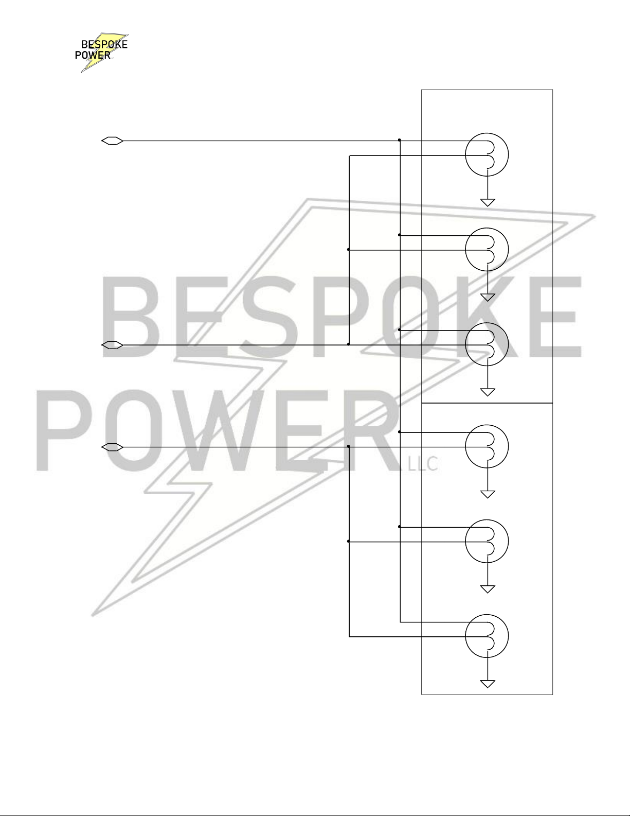
Figure 1. Typical Stock Vehicle Wiring
BL4
1157 (Clear)
Taillight
1
Gnd 2
3
TS/Stop
Outer
BL5
1157 (Clear)
Taillight
1
Gnd 2
3
TS/Stop
Left Stop/Turn Signal
Outer
Right
Mid
BL7
1157 (Clear)
Taillight
1
Gnd 2
3
TS/Stop
Left
Taillights
BL6
1157 (Clear)
Taillight
1
Gnd 2
3
TS/Stop
Right Stop/Turn Signal Inner
Inner
Mid
BL8
1157 (Clear)
Taillight
1
Gnd 2
3
TS/Stop
BL3
1157 (Clear)
Taillight
1
Gnd 2
3
TS/Stop

BESPOKE POWER
5/3/22 Rev01 Visit our website for the latest documentation https://bespokepower.com
Figure 2. Sequencer Wiring
Inner
Right
447 Orange/Red - 16Ga
449/2 White/Blue - 18Ga
Orange/Blue
Red Conn
Connect the Green/Or and Orange/Bl
to the existing Stop/TS wire which goes
to the inner bulb.
J10
CON6
1
2
3
4
5
6
Connect the Black wire
to the chassis.
511 Green - 18Ga
Existing Stop/TL wiring
Left Stop/Turn Signal
Mid
*
Green/Blk
Left
J8
Stop/TL Sequencer
1 2
3 4
5 6
7 8
910
Outer
Taillights
442 Green/Or - 18Ga
444 Green/Blk - 16Ga
Orange/Red BL14
1157 (Clear)
Taillight
1
Gnd 2
3
TS/Stop
BL13
1157 (Clear)
Taillight
1
Gnd 2
3
TS/Stop
57 Black - 18Ga
Green/Orange
BL9
1157 (Clear)
Taillight
1
Gnd 2
3
TS/Stop
BL11
1157 (Clear)
Taillight
1
Gnd 2
3
TS/Stop
J12
CON6
1
2
3
4
5
6
Cut the middle and outer Stop/TS connection
away from the inner bulb connection as indicated
by the red Xs.
BL10
1157 (Clear)
Taillight
1
Gnd 2
3
TS/Stop
Inner
The Green wire is not used unless there is a
Stop signal present (not usually).
Mid
446 Orange/Wht - 16Ga
Outer
Black Conn
448/3 Green/Wht - 18Ga
*
Existing Stop/TL wiring
Right Stop/Turn Signal
BL12
1157 (Clear)
Taillight
1
Gnd 2
3
TS/Stop
J11
CON6
1
2
3
4
5
6
445 Orange/Blue - 18Ga
Green/Red
J9
CON6
1
2
3
4
5
6
443 Green/Red - 16Ga
Orange/Wht
Table of contents
Other Bespoke Recording Equipment manuals


