Aurarum Wombot Exilis Installation guide
Kit
Assembly Instruction Manual
Wombot is a brand of

Introduction
Thank you for purchasing the Wombot Exilis Kit. Please read this assembly manual fully before beginning assembly of
your printer and ensure that you understand e ery step of the assembly process. Please check that all required
components are present before beginning assembly. E ery care has been taken to ensure that you ha e a complete kit of
components which will enable to you assemble your printer howe er should you find anything missing or damaged,
please contact us at sal[email protected] to request replacements. Please note that support for the Wombot Exilis Kit is
limited to email ser ices. Because of the nature of this product, telephone support is not practical.
Health & Safety
Your health and safety are important to us and should be your top priority at all times. Please take care while assembling
your kit, take your time and be careful when using hand tools and while handling the components used to assemble your
printer. Personal safety is ultimately your responsibility. Please ensure that your workspace is clean, tidy and free of any
safety hazards prior to beginning the assembly of your Exilis. Please take care when using sharp tools or handling
aluminium extrusion pieces – they can ha e sharp edges. Please also keep in mind that 3D Printers ha e two main areas
which can reach high temperatures – the heated bed which is capable of sustaining 110 degrees Celsius, and the
Nozzle/Hot End/Extruder, which is designed to operate at a maximum of 250 degrees Celsius. Instant and serious burns
will result from contact with the skin. Once you ha e completed the assembly of your Wombot Exilis, please also
familiarise yourself with the User Manual before attempting to print for the first time as it contains useful information on
how to calibrate and operate your Exilis as well as troubleshooting information.
Assembly Sequence Overview
Assembly needs to take place in the sequence outlined below so that each step is completed correctly and in order. This
will allow you to get your kit assembled in the shortest possible time and reduce the chances that you will ha e to
disassemble the printer later in order to repeat an important missed step. This applies especially to the sliding nuts used
throughout the frame assembly because once assembled, sliding nuts cannot be fitted later without disassembling the
whole frame.
Please take the time to read each step carefully before beginning assembly to make sure that you understand the
requirements of each module and that the required components ha e been laid out on your workspace along with the
appropriate tools.

Required Items to complete the build
All components and fasteners required to complete assembly are included with your Exilis Kit. You will also require some
basic hand tools and equipment as follows:
Base Frame odule
Step 1 – Y Idler odule Pre-Assembly
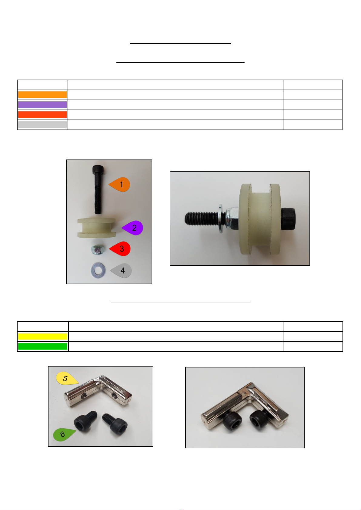
In your kit of parts, locate the following items.
ITE DESCRIPTION QTY
1 BOLT M8 X 45mm CAP HEAD 1
2 IDLER PULLEY LARGE NYLON 1
3 NUT M8 NYLOC 1
4 WASHER M8 FLAT 1
Assemble the Y Idler Module as per the following image then set it aside to be fitted later. Only tighten the lock nut until
it touches the bearing centre on the idler. If this is too tight, the idler pulley will bind rather than spinning freely.
Step 2 – Right Angle Bracket Preparation
In your kit of parts, locate the following items.
ITE DESCRIPTION QTY
5 3030 INTERNAL R/ANGLE BRACKET 8
6 BOLT M6 x 10mm CAP HEAD 16
Screw the bolts into the brackets just enough to hold them in place. Repeat for all 8 brackets.
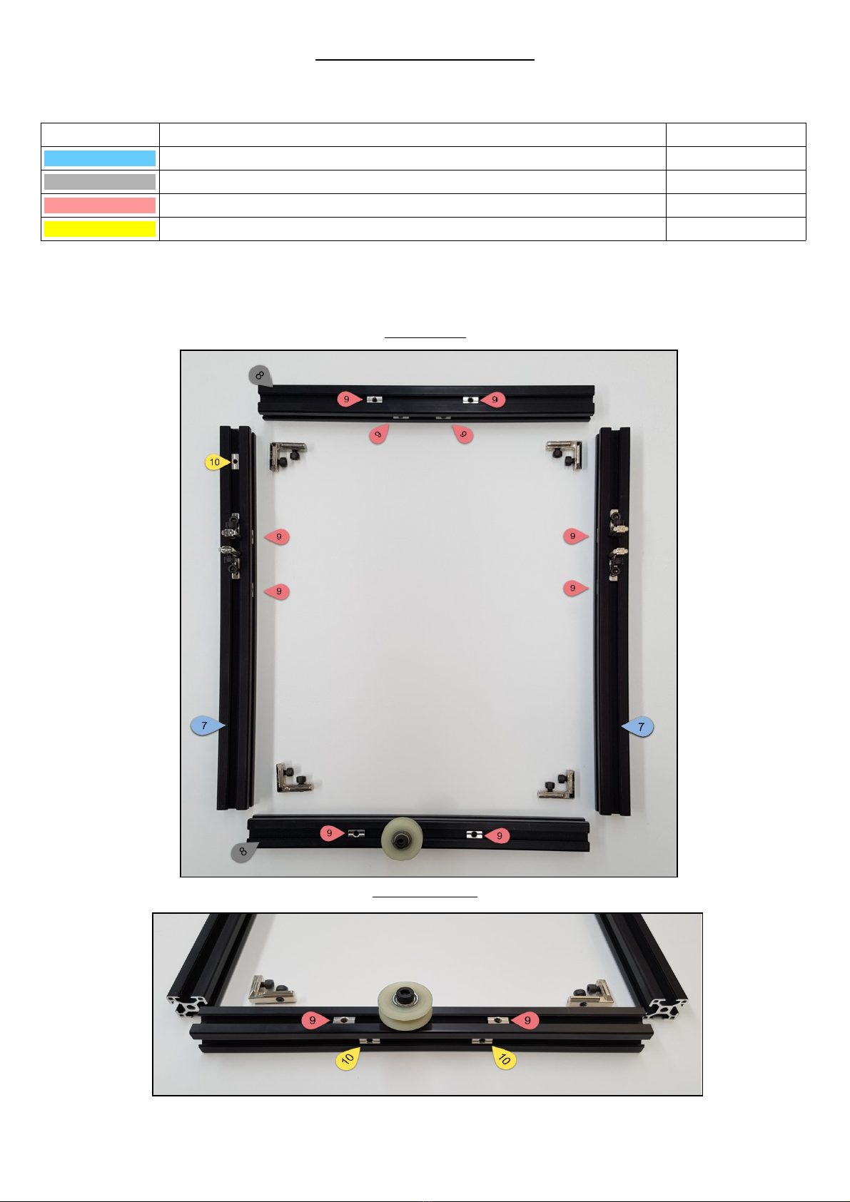
Step 3 – Base Frame Layout
In your kit of parts, locate the following items.
ITE DESCRIPTION QTY
7 3030 EXTRUSION 410mm LENGTH 2
8 3030 EXTRUSION 340mm LENGTH 2
9 3030 SLIDING NUT M6 10
10 3030 SLIDING NUT M5 3
Lay out all Base Frame components on a clean flat surface. Arrange the Aluminium Extrusion pieces by length and insert
all Sliding Nuts and Right Angle Joints as per the images according to the Item Number in the component listing. Secure
the Y Idler Module to the frame firmly.
The Y Idler Module should be towards the left of the front rail.
TOP VIEW
FRONT VIEW

Step 4 – Base Frame Assembly
Once all sliding nuts, right angle brackets and Y idler ha e been fitted, gently slide together the frame on a flat surface
and gently tighten each of the cap head screws in the right angle brackets so that they can still be adjusted or mo ed.
Make sure that the frame is true and square before tightening the four corner brackets in the base of the frame using a
square as follows:
All corner joints must be at 90 degrees (perpendicular). Left and Right rails must be parallel as must the front and rear
rails. Use a measuring tape or ruler to make sure that the distance between each set of rails remains constant from end to
end – e en if this results in a slight gap at one end where extrusion pieces meet.
Step 5 – Fitting the stepper motors.
Once the bed base components ha e been tightened, locate the following items in your kit as per the below image.
ITE DESCRIPTION QTY
11 STEPPER MOTOR NEMA 17 3
12 STEPPER MOTOR BRACKET 3
13 BOLT M6 x 12mm CAP HEAD 6
Fit the motors into their brackets and fasten the stepper motors to the base frame loosely at the rear of the base as per
the following images, utilising the sliding nuts you fitted to the frame at the beginning. Fit but do not tighten these
motors in place yet, they must be able to slide into their final position later for correct alignment with other components.
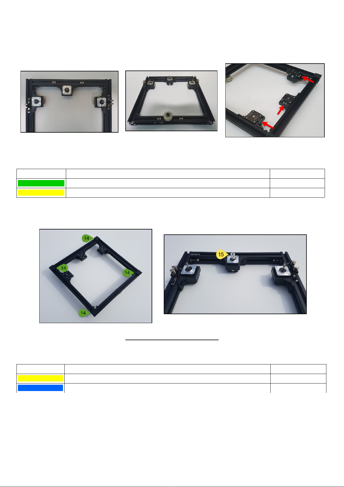
Please note that the Y motor bracket (the one in the middle) is modified - it has a small notch cut out in one mounting
arm to a oid the bed rail which will be fitted in the next step. Please also obser e the orientation of the connectors on the
stepper motors when fitting, as per the below images:
Locate the following items in your kit and fit them as per the below images:
ITE DESCRIPTION QTY
14 SELF ADHESIVE RUBBER FOOT 4
15 PULLEY GT2 20 TOOTH 1
Fit the small rubber feet to the base in each corner of the printer frame
as well as the GT2 20 tooth pulley for the Y motor. Pulley final position may need to be adjusted later to align with belt.
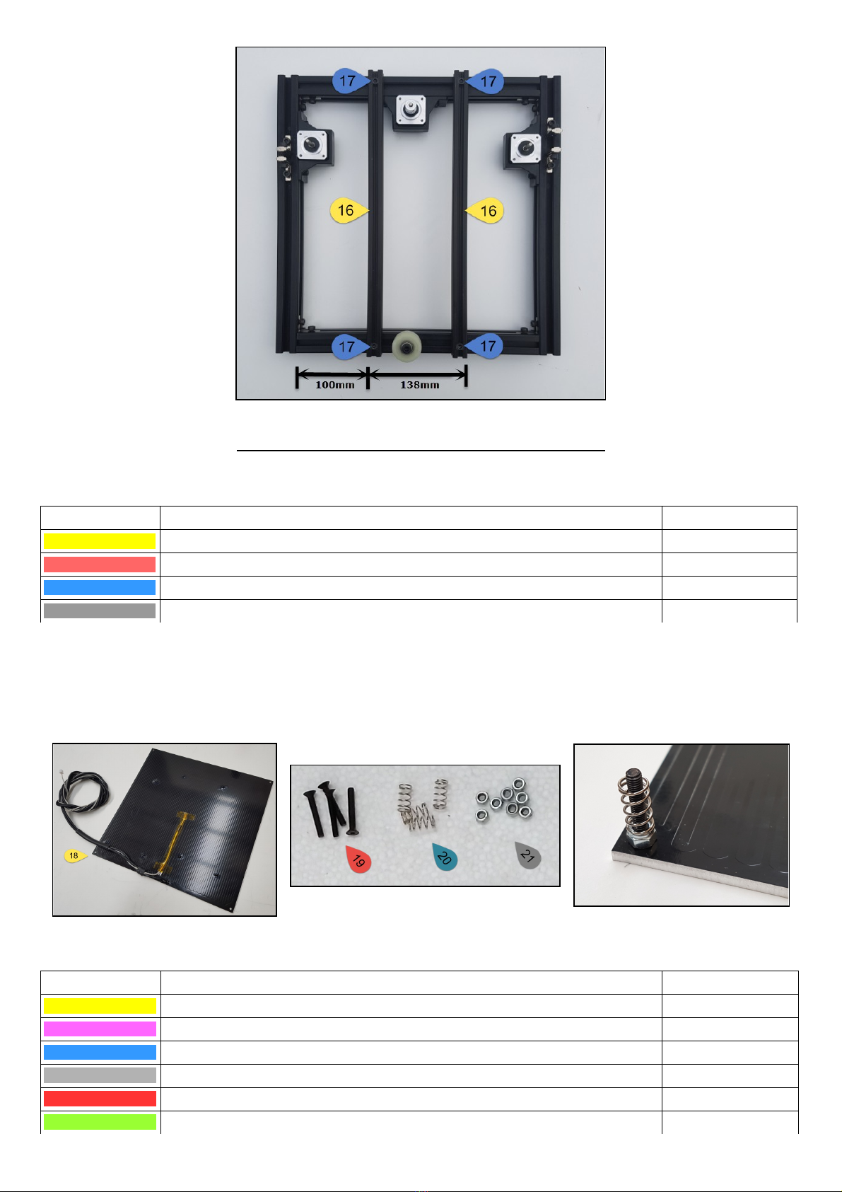
Step 6 – Fitting the bed rails.
Locate the following items in your kit of parts:
ITE DESCRIPTION QTY
16 2020 EXTRUSION BLACK 410mm – PRE-DRILLED BED RAILS 2
17 BOLT M6 x 20mm CAP HEAD 4
Fit the pre-drilled rails to the top of the base frame utilising the sliding nuts that were positioned in the frame at the
beginning (do not tighten them yet, they must be able to slide into their final position). Measure out the distances as per
the image and once they are the correct distance from the side rail and each other, tighten them in place firmly. Keep in
mind that these two rails must be perfectly parallel to the side rails of the printer as well as each other in order for the
printer bed to tra el correctly and under a uniform tension while printing.
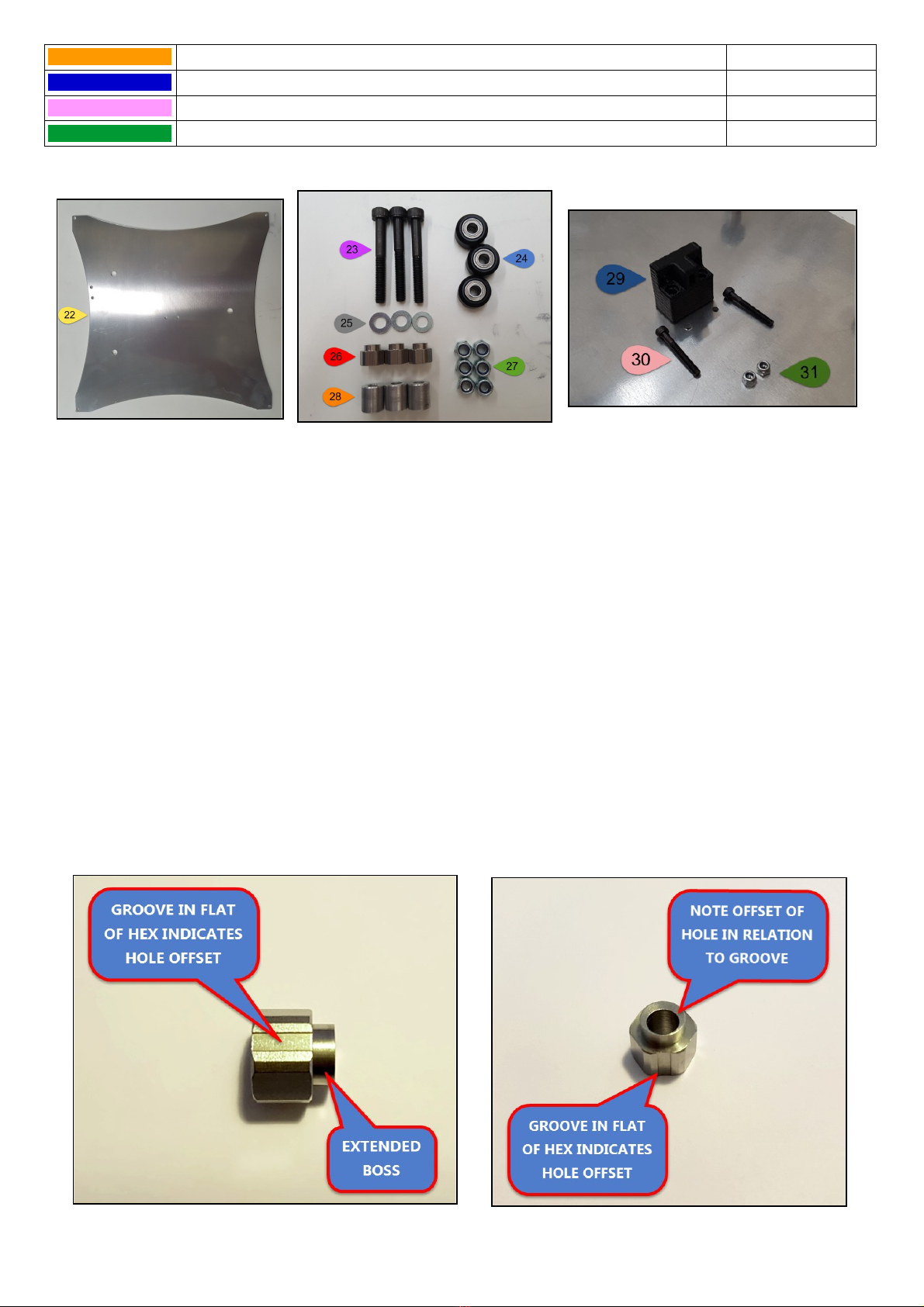
Step 7 – Assembling the Heated Bed Platform.
In your kit of parts, locate the following items:
ITE DESCRIPTION QTY
18 PRE-WIRED WOMBOT MK4 HEATED BED 1
19 SCREW COUNTERSUNK M3 x 20mm 4
20 BED SPRING 4
21 NUT M3 NYLOC 4
Fit the Countersunk M3 screw from the top side of the heated bed (side with the Wombot Logo and warning symbols)
and secure in place on the underside of the bed (side with tracks) with nyloc nuts firmly. Then simply place the spring o er
the screw so that it rests on the nyloc nut as per the below image. Repeat this for all four corners of the bed and set aside
(springs up so that you don't lose them) for for the next step of the bed assembly.
In your kit of parts, locate the following items and lay them out on your table:
ITE DESCRIPTION QTY
22 PRE-MILLED BED TROLLEY 1
23 BOLT M5 x 40mm CAP HEAD 3
24 DELRIN WHEEL BLACK 3
25 WASHER M5 FLAT 3
26 ECCENTRIC NUT M5 3
27 NYLOC NUT M5 6
28 BED SPACER ALUMINIUM 3
29 BED BELT MOUNTING BLOCK 1
30 BOLT M3 x 20mm CAP HEAD 2
31 NUT M3 NYLOC 6
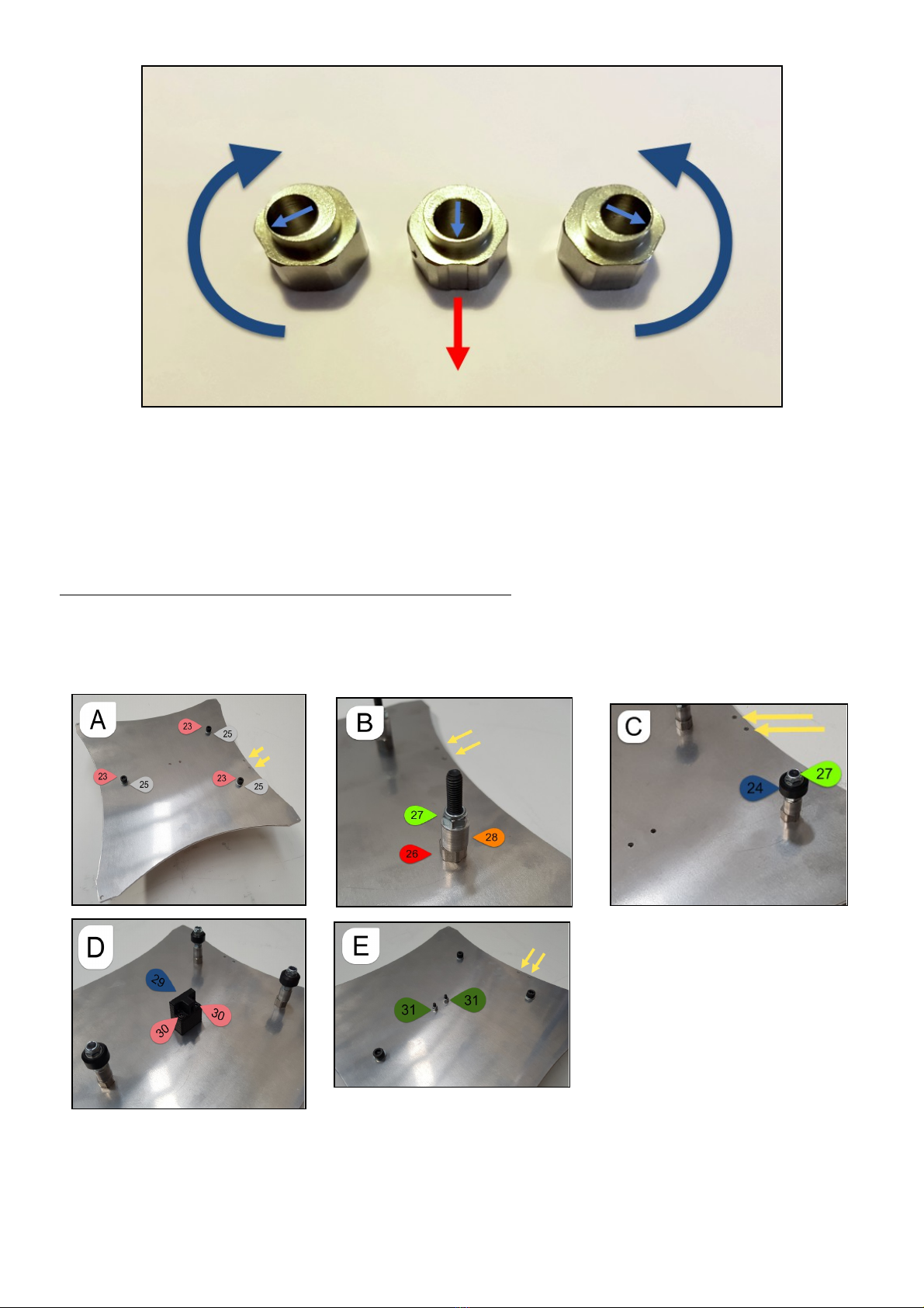
An Important Note on Eccentric Nuts and their function:
Before beginning assembly of your Heated Bed Platform (or Extruder Carriage Module in a later step), it is essential that
you understand the installation and correct operation of Eccentric Nuts. Eccentric Nuts are small mechanical de ices which
resemble a normal nut. There are howe er three important differences which must be obser ed: 1. They ha e an extended
cylindrical boss (smooth external barrel) which extends past the body of the “Hex Shaped” portion of the Nut, 2. The hole
through the middle of the Eccentric Nut is not actually in the centre – it is offset to one side (indicated by a groo e in one
side of the hex of the nut closest to the perimeter of the hole). This is also referred to as being “off-centre” and 3. there is
no thread in the centre of the nut, it is a smooth bore through which a bolt or shaft can be inserted.
The purpose of an eccentric nut is to pro ide minor adjustment to the final position of an attached de ice or assembly (in
this case, a black delrin wheel/bearing). This is achie ed by securing the de ice under tension and rotating the nut to
achie e a shift in the location of the component - hence mo ing the position of the attached de ice proportionate to the
degree of rotation applied to the nut and dependent on the starting position of the off-centre hole.
Please see below images illustrating these principals and make sure you understand them before proceeding.
The same principals can be applied at a later stage to the eccentric nuts used on the Extruder Carriage Module:
Proceed by fitting the Bolts, Eccentric Nuts, Spacers and Black Delrin Wheels to the bed trolley as per the below images
while noting the orientation of the aluminium bed trolley in relation to the mounting holes in the centre and along the
edge (yellow arrows). Please also note that while the eccentrics and delrin wheels must be held in place firmly, – they
should not be o er tightened so that free mo ement is impeded. Please also take extra care that the eccentric nuts are
orientated correctly to allow for the greatest flexibility for rotation during tightening of the completed bed assembly to
the base frame.
Important Note on tensioning down the Black Delrin Bearings: This must be done ery gently and with great care.
Only tighten down the Nyloc Nuts onto the Bearing as much as is needed to stop any play between the inner bearing
hubs and the faces of the two Nyloc Nuts. They must be free spinning, but not allowed to mo e up and down the bolt
shaft. O er-tightening these bearings will result in too much friction, restricted rotation and permanent damage to the
bearings which you will then be required to purchase separately to replace.
Place the heated bed assembly from the pre ious step on your work surface (springs upward). Install the assembled
aluminium bed trolley onto the heated bed so that the M3 screws pass through the pre-drilled holes in the trolley. Fasten
with Nyloc Nuts as per the below images. Please obser e the correct orientation of the heated bed to the trolley and the
path of the wiring loom from the heated bed. Temporarily cable tie the loom to one of the two holes on the aluminium
trolley to secure it as per the yellow arrows in the following images.
The M3 Nyloc Nuts holding the heated bed to the aluminium trolley should ha e between ½ mm and 1mm pass-through
of thread from the bolt. Do not concern yourself with making each corner of the heated bed the same distance from the
trolley at this point, they will need to be adjusted later to le el the bed manually prior to printing.
Gently guide the completed bed trolley assembly onto the bed rails of the Base Frame so that the black delrin wheels run
along the external side groo es of the extrusion, as per the below images.
Once fitted, you can adjust the eccentric nuts to pro ide the correct tension between the Delrin wheels and the Bed Rails
by turning either clockwise or counter-clockwise using an open-end spanner. We suggest that you begin with the
eccentric on the left hand side of the bed (the one on it's own) which should pro ide sufficient adjustment to gi e
adequate tension. The opposing two eccentrics can be adjusted if additional tightening is required as well as pro iding
adjustment of the bed to achi e squareness in relation to the base frame. The bed should be reasonably free mo ing, but
require some effort to dis-lodge if pushed downwards towards the rails. It should be tight enough to remain flat and
tra el from front to back without becoming either o er-tight, or loose enough to wobble at full tra el.
Turn your printer base o er so that the heated bed is on the table and you can access the underside of the frame.
In your kit of parts, locate the following parts:
ITE DESCRIPTION QTY
32 GT2 BELT 6mm WIDTH 1 Metre
33 GT2 BELT WEDGE 2
34 GT2 BED BUCKLE 1
35 BOLT M3 x 25mm CAP HEAD 2
36 NUT M3 NYLOC 2
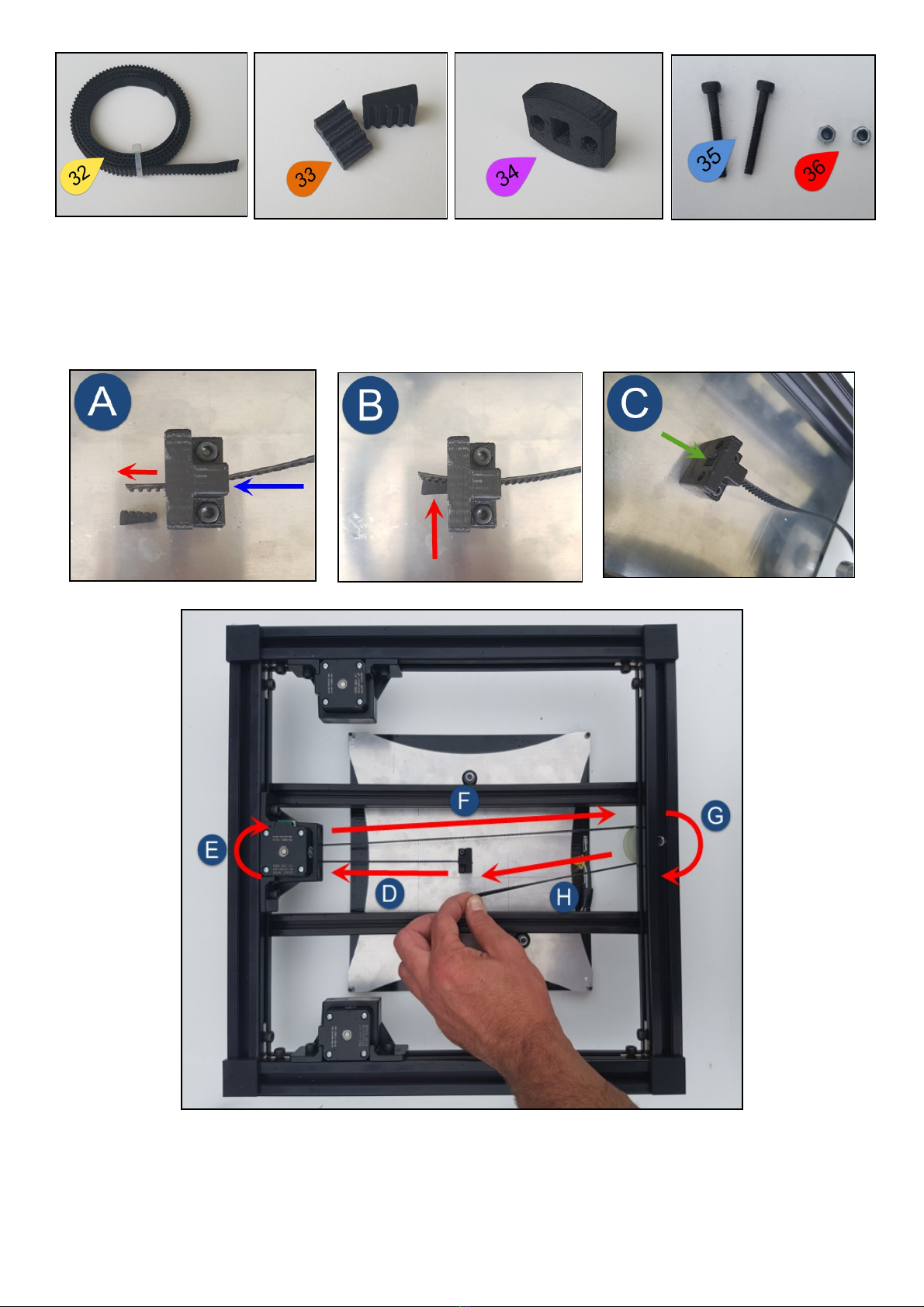
Pass the GT2 Belt through the Bed Belt Mounting Block with the teeth (rounded portions of the belt) in such a way that
the belt will tra el towards the Y motor and engage with the pulley. Place the GT2 Belt Wedge on the belt so that it
engages with the belt – all teeth on the Belt Wedge must be co ered by the Belt. Insert the Belt with mated into the gap
in the Mounting Block. Pull it towards the Y motor until tight. Use pointy nose pliers to achie e a tight fit. Run the belt
around the Y motor pulley, back along the side of the Bed Mounting Block, around the Y idler and back again towards the
Bed Mounting Block as per the below images:
Place the GT2 Bed Buckle o er the Belt with the wider opening towards the Bed Belt Mounting Block. Insert the two
M3 x 20mm Cap Head Bolts through the Mounting block and into the Bed Buckle. Note that there must be sufficient
thread left on the screws to fit the M3 Nyloc Nuts. Insert the GT2 Belt Wedge in an appropriate position so that when
inserted and pulled tight, there is still at least a 10mm gap between Block and Buckle. Fit the M3 Nyloc Nuts and tighten
as per the following images so that the belt is under tension, but not o er tightened.
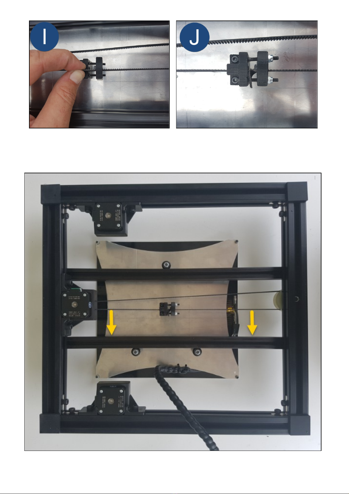
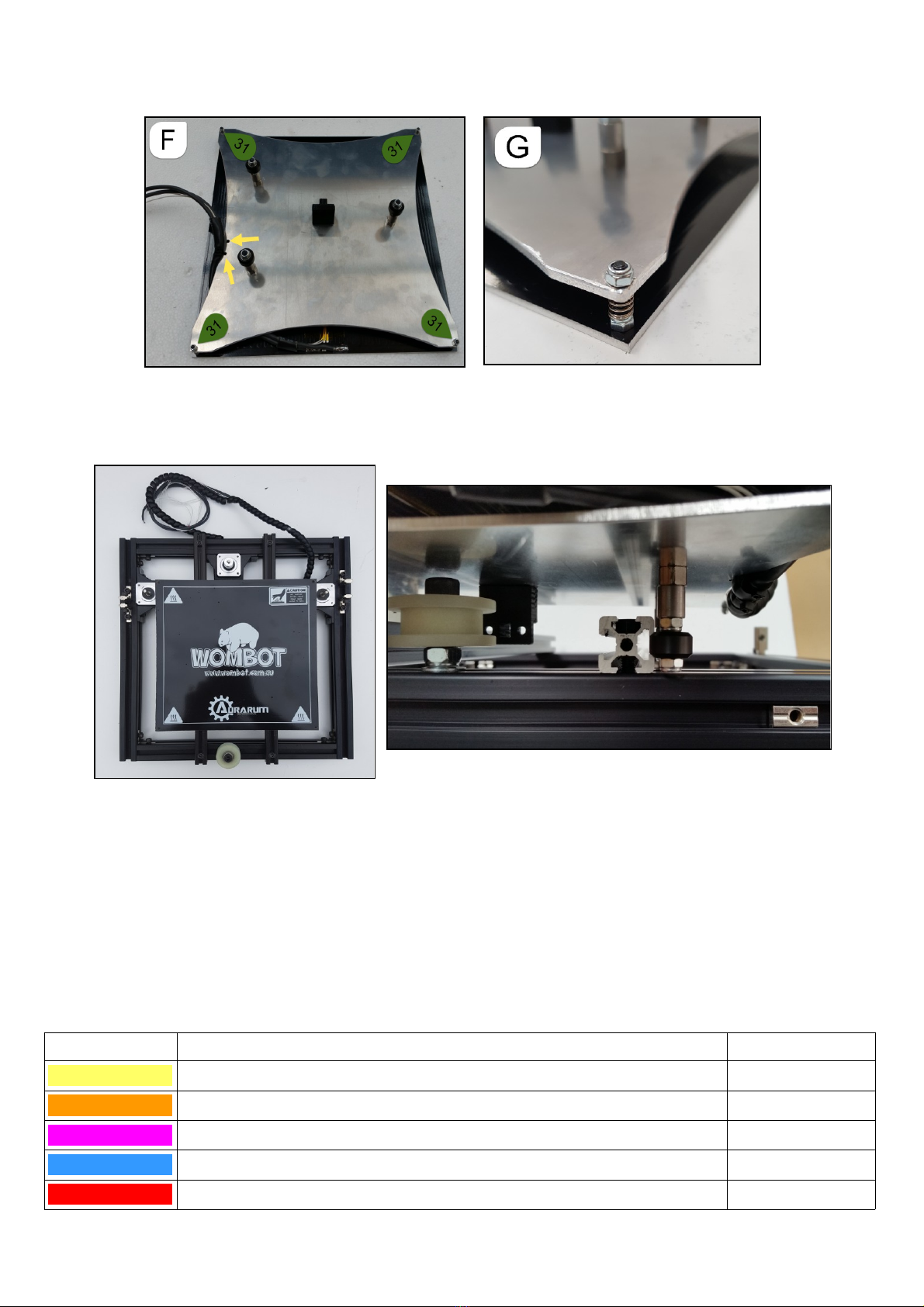
The underside of your frame should look like this once the Y Belt work is finished. Adjust the position of the Y motor so
that the belt runs perfectly straight and parallel to the bed rail as indicated by the yellow arrows below. Adjust the height
of the GT2 Pulley on the Y motor shaft so that the belt is flat and straight in relation to the rail and Y Idler. This will
eliminate chaffing of the belt and promote smooth operation and long belt life.

Using a cordless drill fitted with a 3mm diameter drill bit, drill two holes as per the below image so that the loom coming
from the heated bed assembly can be anchored with cable ties to the bed rails:
Locate the following items in your kit of parts for the next step:
ITE DESCRIPTION QTY
37 SPIRAL WRAP BLACK NYLON 1
38 CABLE TIE 2.5mm x 100mm 2
39 ANDERSON CONNECTOR ASSEMBLY 1
40 BOLT M5 x 10mm CAP HEAD 1
41 STEPPER MOTOR CABLE 900mm 2
42 END STOP ASSEMBLY 1
43 2020 SLIDING NUT M4 1
44 BOLT M4 x 8mm CAP HEAD 1
45 STEPPER MOTOR CABLE 400mm 1
46 COVER STRIP BLACK SYSTEM 30 1
47 3D PRINTED EXTRUSION CLIP 1
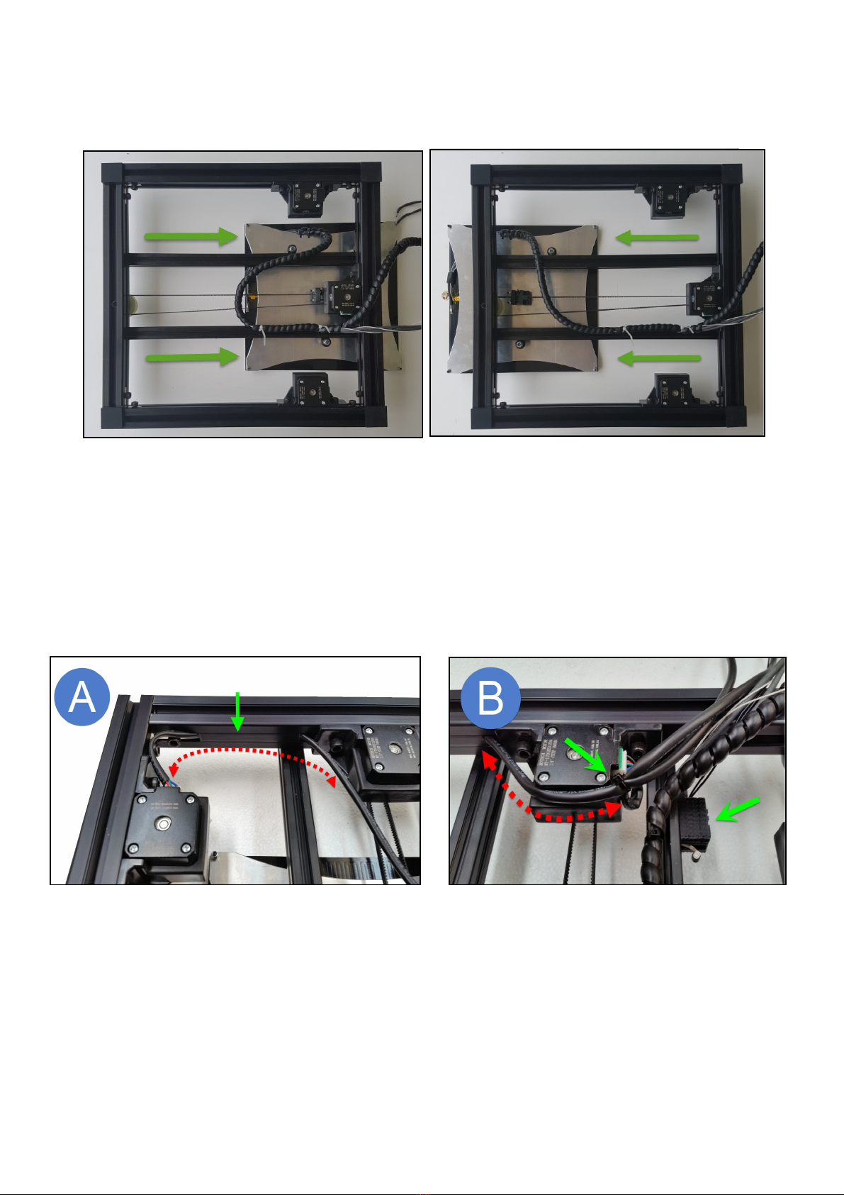
Wrap the heated bed wires with spiral wrap as a protecti e sheath. Cable tie the loom to the bed rail as per the below
images making sure that there is sufficient strain relief (extra length) on the loom so that it can tra el the full length of the
bed, front to rear, without any tension or binding:
Fit one of the 900mm stepper looms to the R/Hand Z motor. Clip the loom into the frame as per the below image using
the co er strip to keep the loom in place. Pass the loom around the Y motor bracket. Fit the second 900mm stepper loom
to the Y motor and cable tie it to the first stepper loom to secure the two looms together. Fit the Y end stop assembly
using a 2020 M4 Sliding Nut and M4 x 8mm Cap head screw. Don't worry about the final position of the Y end stop – it
will be adjusted later prior to printing, just make sure that you allow a little spare cable so that it can slide back and forth
30mm or so.
Helpful Hint – Mark the stepper motor looms and endstops according to their function – this will make wiring up the
motherboard simpler and faster later on.
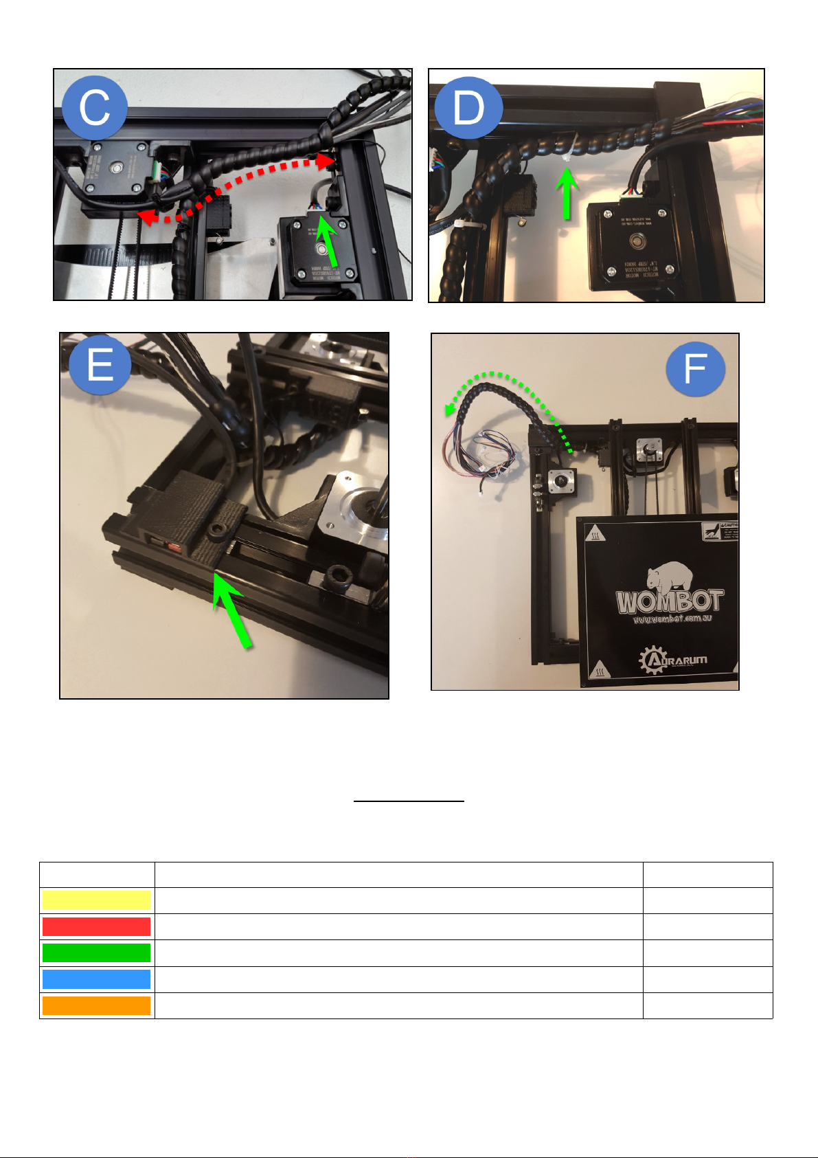
Join together the stepper motor looms and Y end stop loom. Wrap them together with the black spiral wrap coming from
the Heated Bed Assembly. This piece of spiral wrap will continue up to the bottom of the motherboard enclosure at a later
stage. Plug in the 2nd Z motor loom (400mm length) and pass it through the frame to the top. Using the 3D Printed
Extrusion Clip as an anchor, cable tie the wrapped loom to the rear of the frame as per the following images. Turn o er
your printer frame. Fit the Anderson Main Power connector to the top side left of the frame using the sliding nut fitted
pre iously and continue to wrap the wiring looms together, including the 2nd Z motor loom as per the image below.
Please ensure that there is not excessi e strain on any of the cables and that they flow around corners rather than being
pulled tight or bent harshly. 3D printers are subject to regular ibration and constant mo ement – an o erly tight or
tensioned wiring loom can lead to connector failure or wire breakage during printing which can also lead to irreparable
damage to stepper dri ers if disconnected while powered up!
Your Exilis Printer Base Frame can be set aside for now while you pre-assemble the remaining modules before fitting them
to the printer frame.
Step 9 – X Rail
In your kit of parts, please locate the following items and lay them out on your table:
ITE DESCRIPTION QTY
48 X MOTOR BRACKET 1
49 PULLEY GT2 20 TOOTH 1
50 STEPPER MOTOR NEMA 17 1
51 BOLT M3 x 10mm CAP HEAD 4
52 WASHER M3 FLAT 4
Place the Pulley on the motor shaft with the grub screws towards the motor body but do not tighten yet. Load one flat
washer onto each M3 Bolt and fit the motor bracket to the motor face as per the following images. Note the orientation
of the motor connector to the bracket arms:
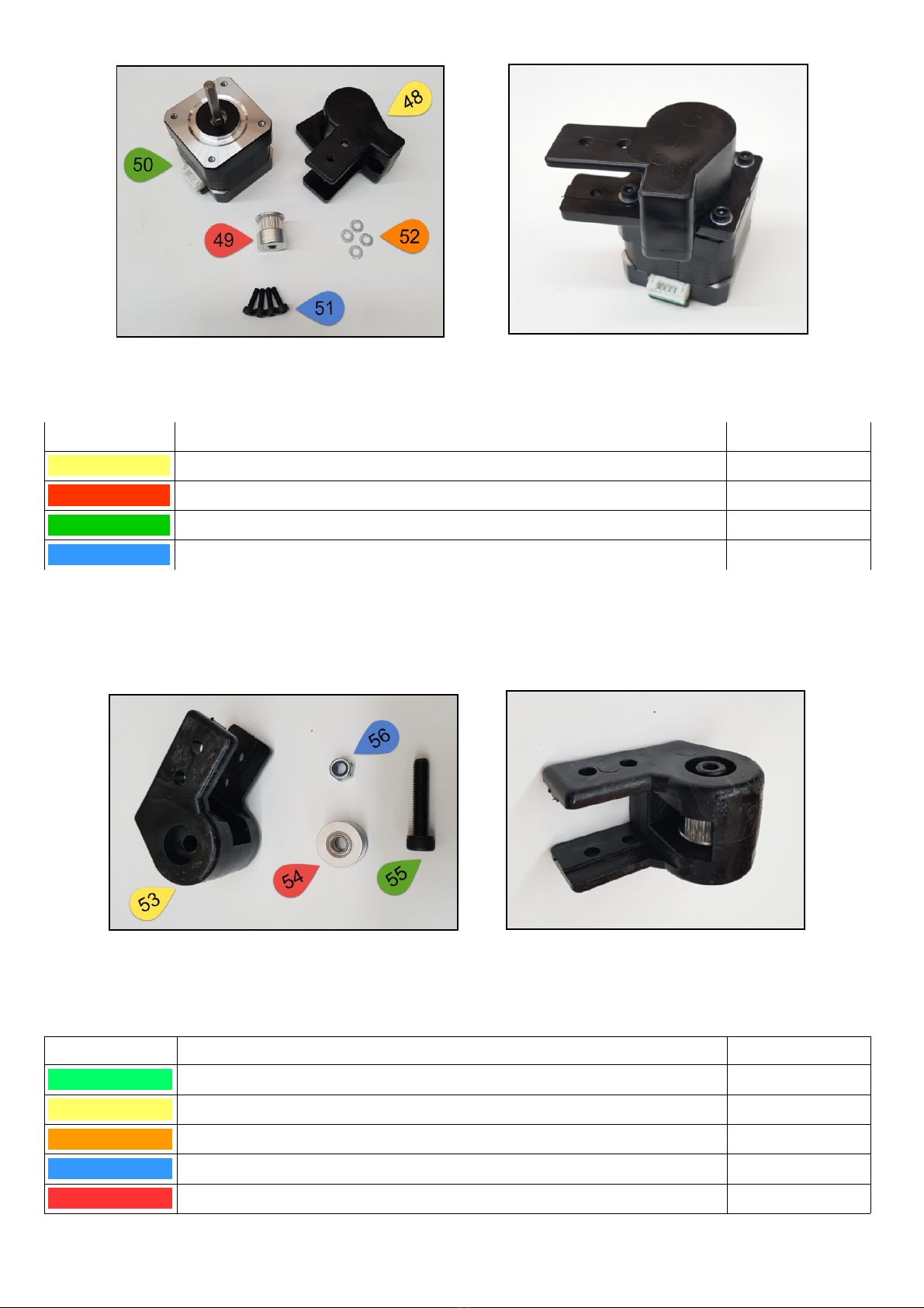
Set aside the assembled motor and locate the following items in your kit of parts:
ITE DESCRIPTION QTY
53 X IDLER HOUSING 1
54 IDLER PULLEY GT2 16 TOOTH 1
55 BOLT M5 x 25mm CAP HEAD 1
56 NUT M5 NYLOC 1
Place the Idler Pulley inside the Housing and insert the M5 bolt from the top of the housing. Make sure it passes through
the centre of the idler pulley and out through to the other side of the housing. Fasten the bolt in place with the nyloc nut
from the bottom. Please note orientation of the bolt and nut in relation to the arms on the housing. Please don't o er-
tighten, the nut only needs to be tight enough to stop the bolt from turning or shifting up or down.
Please set aside the assembled X idler assembly and locate the following items in your kit of parts:
ITE DESCRIPTION QTY
57 X RAIL BRACKET 2
58 DELRIN BEARING WHITE 4
59 BOLT M8 x 40mm CAP HEAD 4
60 NUT M8 STANDARD HEX 4
61 NUT M8 NYLOC 4
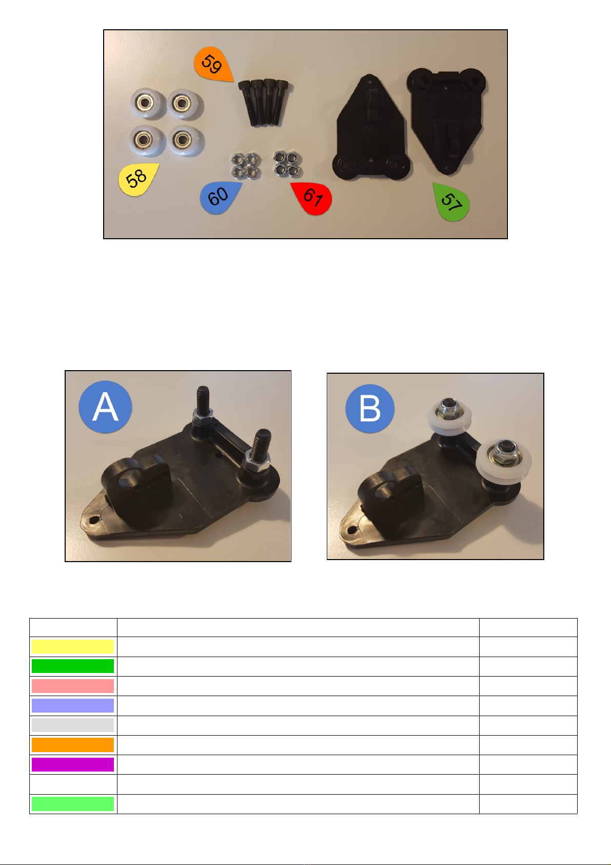
Assemble the X Rail Brackets by inserting the M8 Bolts into the bracket from the flat side of the bracket. Lock them in
place using M8 Standard Hex Nuts. Gently lock in place by using a ring spanner or adjustable wrench and a hex key.
Please do not o er-tighten them as this may cause the bracket to compress and split o er time. Next, place the White
Delrin Bearings o er the bolts and fasten in place tightly with the M8 Nyloc Nuts. Please see the images below for correct
orientation of components.
Please set aside the X rail brackets for now and locate the following items in your kit of parts:
ITE DESCRIPTION QTY
62 2020 EXTRUSION BLACK 445mm 1
63 BOLT M4 x 12mm CAP HEAD 4
64 BOLT M4 x 10mm CAP HEAD 8
65 WASHER M4 FLAT 12
66 WASHER M4 SPRING 4
67 2020 SLIDING NUT M4 12
68 END STOP ASSEMBLY 1
69 STEPPER MOTOR CABLE 550mm 1
70 SPIRAL WRAP BLACK NYLON 1
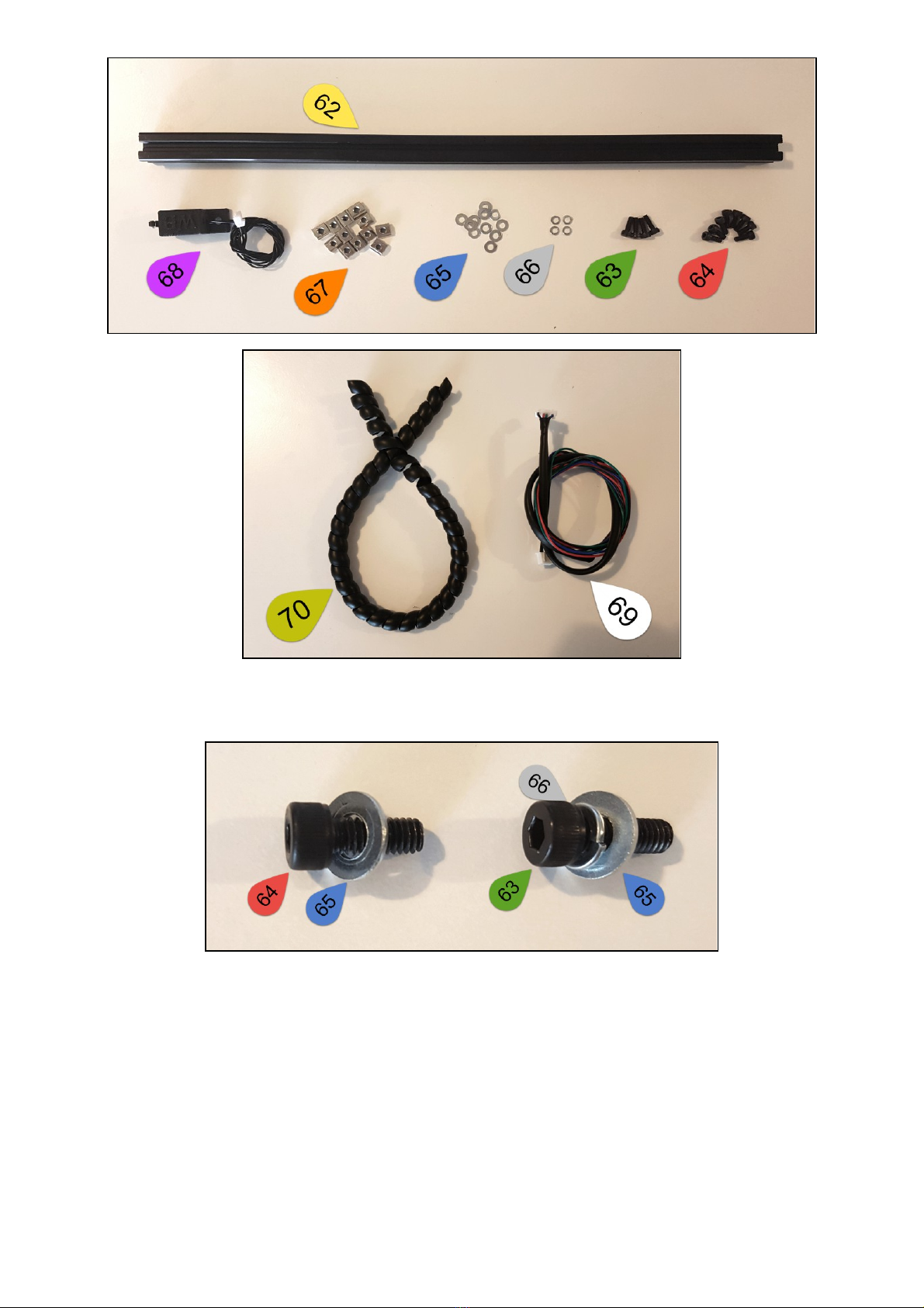
Place Flat Washers on the M4 x 10mm Cap Head Screws and set them aside, then place Spring Washers and Flat Washers
on the M4 x 12mm Cap Head Screws and set them aside as per the following images:
Locate the piece of 445mm long 2020 Black Extrusion – this ser es as the chassis of the X rail which will tra el up and
down on the Z axis while ser ing as the carriage for the extruder to mo e left to right while printing (X Axis). Please take
the X Motor Module and slide it o er the end of the extrusion as per the below images. Slide 2 of the M4 sliding nuts into
the 2020 extrusion and fasten the bracket in place using the 10mm long M3 screws you prepared in the pre ious step. Flip
the extrusion o er and slide one sliding nut along the extrusion to secure the bottom of the motor bracket:

With respect to the orientation of the X Motor Module, please load the rest of the M4 Sliding nuts as per the below
images. Please note that there are no sliding nuts on the FRONT of the X rail, only TOP, REAR and BOTTOM:
Table of contents


