Aurora Multimedia DIDO User manual
DIDO
Installation Manual
Manual Number 041101
Firmware Version 1.06 and above
205 Commercial Court
Morganville, NJ 07751
(732) 591-5800
www.auroramultimedia.com

DIDO Installation Manual
TABLE OF CONTENT
1INTRODUCTION .................................................................................................................................2
ACCESSORIES.............................................................................................................................................4
1.1 OPTIONAL ACCESSORIES ..................................................................................................................5
2IR REMOTE AND BASIC KEY FUNCTIONS .................................................................................6
3QUICK START GUIDE .......................................................................................................................7
4LCD / KEYPAD.....................................................................................................................................8
5CONNECTIONS ...................................................................................................................................8
5.1 A/V &CONTROL CONNECTORS ........................................................................................................8
5.2 POWER CONNECTOR .........................................................................................................................9
5.3 EXAMPLES CONNECTIONS ................................................................................................................9
6OPERATING THE DIDO ..................................................................................................................10
6.1 REMOTE CONTROL FUNCTIONS ......................................................................................................10
6.2 MENU STRUCTURE .........................................................................................................................11
6.2.1 MAIN MENU ...............................................................................................................................11
6.2.2 WINDOW SETUP .........................................................................................................................12
6.2.3 LAYOUT SETUP...........................................................................................................................14
6.2.4 OUTPUT SETUP ...........................................................................................................................14
6.2.5 SOUND SETUP.............................................................................................................................15
6.2.6 PRESET SETUP ............................................................................................................................15
6.2.7 SYSTEM SETTINGS......................................................................................................................15
6.2.8 SIGNAL TIMING ..........................................................................................................................17
7TROUBLESHOOTING......................................................................................................................18
8FIRMWARE UPDATE.......................................................................................................................19
9RS-232 PROTOCOL...........................................................................................................................20
10 SPECIFICATIONS .........................................................................................................................23
10.1 SUPPORTED TIMING........................................................................................................................23
10.2 POWER SOURCE ..............................................................................................................................24
10.3 CONNECTION TERMINALS ...............................................................................................................24
10.4 DIMENSIONS...................................................................................................................................26
10.5 WEIGHT..........................................................................................................................................26
11 LIMITED LIFETIME WARRANTY............................................................................................27
12 FCC PART 15 STATEMENT ........................................................................................................28

DIDO Installation Manual
2
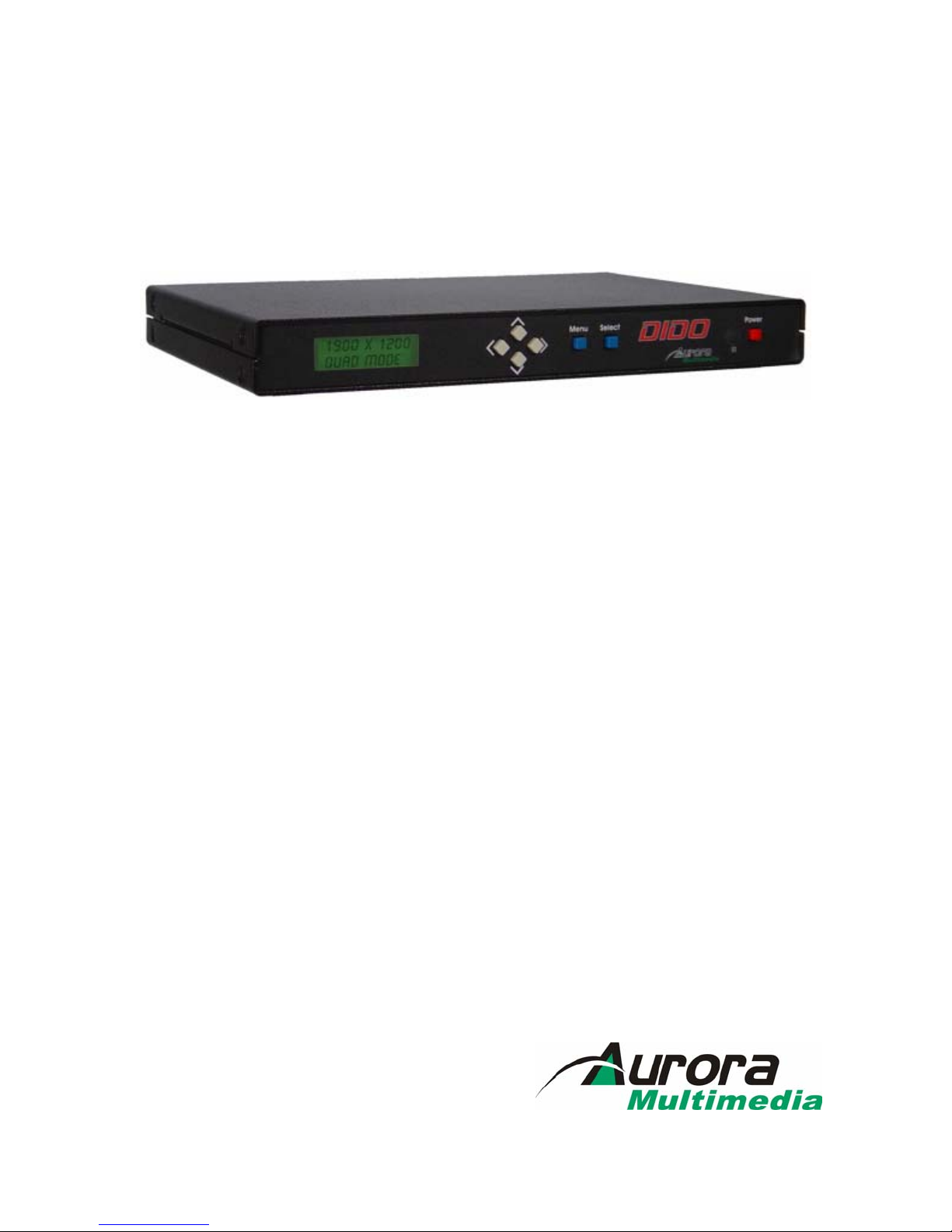
1 Introduction
The DIDO is a high quality video processor engine. The DIDO supports advanced functionality, like
video format /scan rate conversions, audio effects, rotation, and window effects. All this can be
controlled via IR remote and RS-232 and is small enough to fit in tight areas. The progressive output(s)
produces a high quality image using the latest 3:2 / 2:2 pull-down, motion handling, and noise reduction
technologies.
• Up to 165MHz bandwidth on the inputs and outputs.
Allows resolutions to 1900 x 1200 @ 60Hz and can de-interlace 1080i to 1080p
•Image enhancing capabilities including Motion Adaptive De-interlacing, Low-angle
Directional Interpolation, 3:2 & 2:2 inverse pull-down, Moiré cancellation color
correction, adaptive flesh tone adjustments, image zoom & shrink.
•The powerful AARE (Aurora Advanced Rotation Engine) Picture-and-Picture (PAP)
engine offers several modes of operation including:
1. Hi-resolution Quad Image or Side-by-Side (split screen) images. Perfect for
teleconferencing, security, command and control applications.
2. Image Rotation (for digital signage)
3. Translucent Overlays to maximize main image size while still seeing PiP
•Accepts digital and analog video inputs through a combination DVI/ RGBHV/ YPbPr
connector and S-Video/Composite input connectors
•Includes audio propagation delay compensation for correct sync with video
•Internal Event Scheduler with Real Time Clock allows AARE special effects to be
scheduled locally and between DIDO units when connected via the RS-485 bus
•Shipped with a Full Featured IR Remote Control and Interface Cables
•Firmware upgradeable. New firmware releases are easily uploaded to the DIDO
with the Flash utility, both of which are available for free from Aurora's website.
Example Setup using the DIDO quad mode:

DIDO Installation Manual
3
Just a few examples of the DIDO’s capabilities:
Single Image Scaling Side by Side Quad Mode
Single with PiP Single with Translucent PiP
Single Rotated Dual Rotated Tri Rotated
Single Rotated PiP Single Rotated Translucent PiP
\
Video Wall Mode Rotated Using 3 DIDO Units
DIDO Installation Manual
4
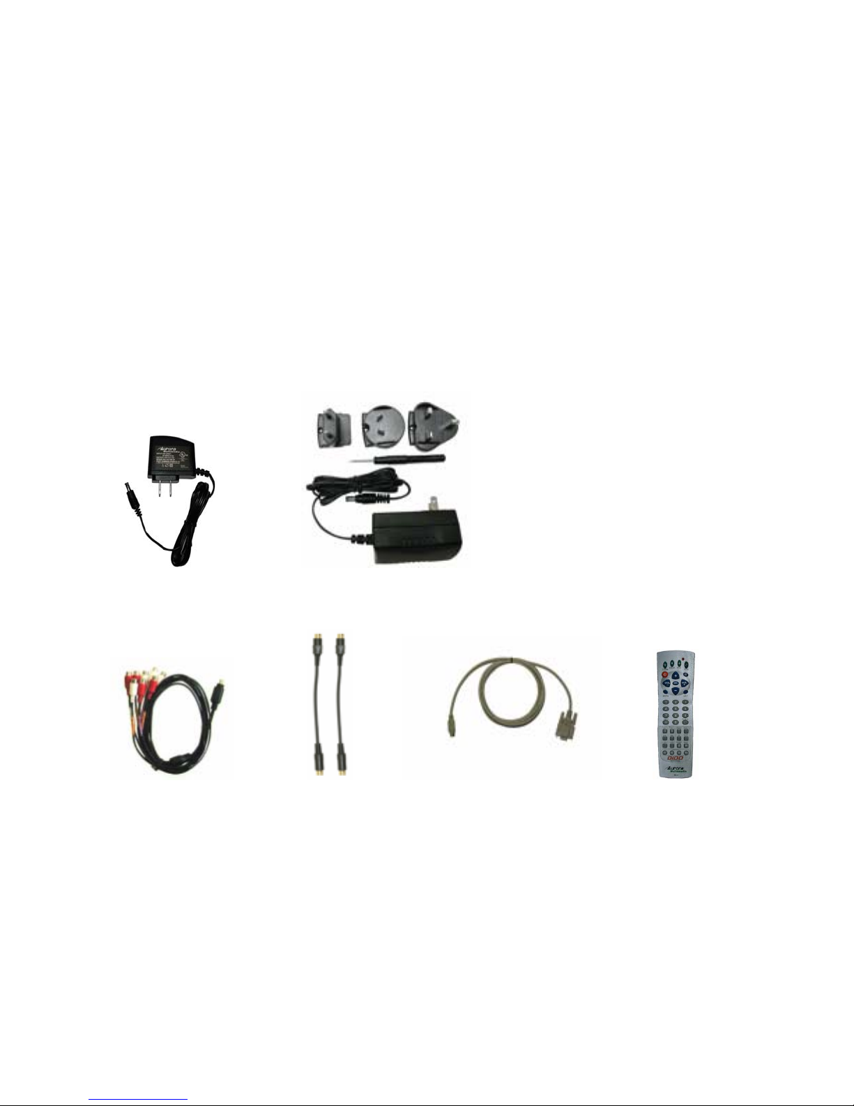
Accessories
The accessories supplied are:
-12v 15watt DC wall supply or International Supply Kit if applicable
-8 pin mini DIN to 8 RCA Female audio I/O cable
-2 qty S-Video to Composite Video Adaptors
-RS-232 Adaptor Cable 6 Pin Mini-Din to 9 Pin D-Sub
-IR Remote
All supplied components are shown on the picture below:
12v 15 Watt Supply International Supply with Adaptors
Audio Breakout Cable S-Video to Video Adaptors RS-232 Control Cable IR Remote
DIDO Installation Manual
5
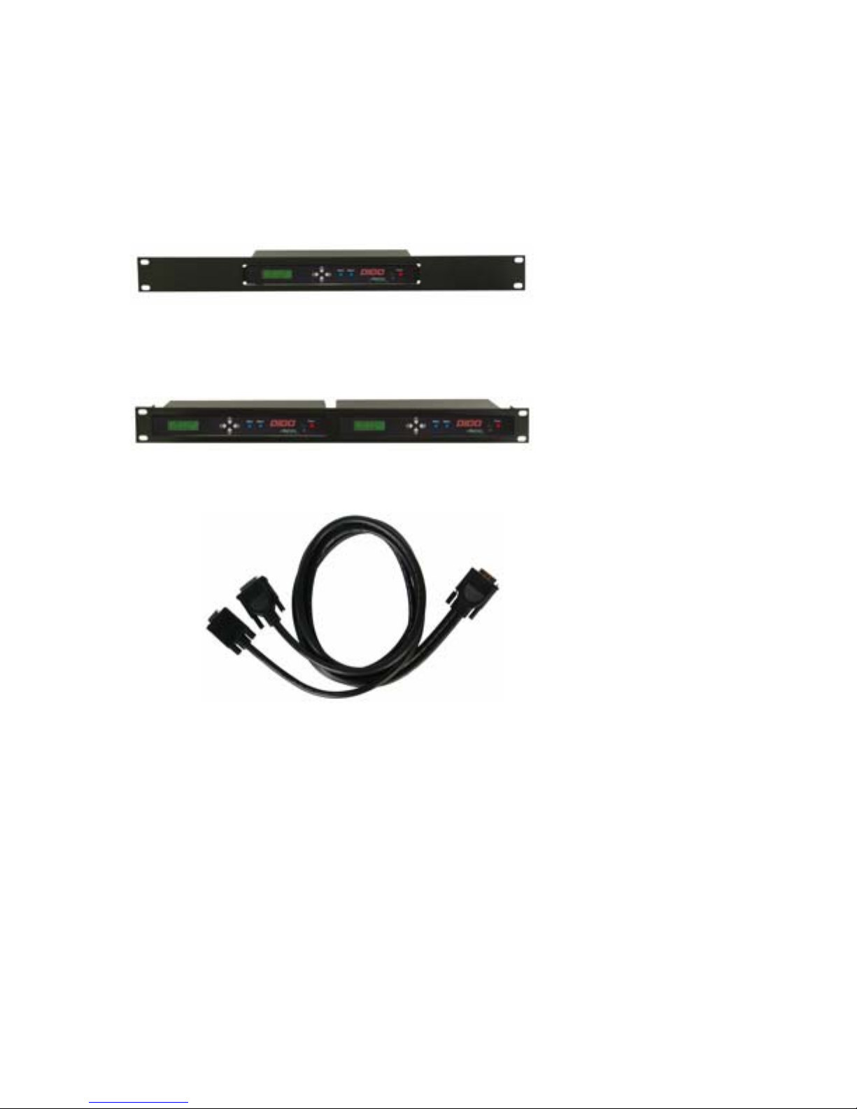
1.1 Optional Accessories
Optional accessories available from Aurora Multimedia Corp.:
SRK-001 Single Rack Mount Kit
DRK-001 Dual Rack Mount Kit
CA0016-6 200MHz 6ft DVI-I to DVI-D / VGA(15pin D SUB) Breakout Cable

DIDO Installation Manual
6
2 IR Remote and basic key functions
The DIDO can be controlled using an IR remote controller. It utilizes the built in IR sensor or can be
controlled via front panel and/or RS-232.

DIDO Installation Manual
7
For details of DIDO operation refer to the corresponding chapter of this document. Below is a brief
description of the remote transmitter and the keys used for DIDO control.
IR Remote Function
POWER Toggles Power on and off
ZOOM Brings up Zoom selection for each window 0-100%
CROP Brings up Crop selection for each window 0-100%
POS Brings up Position selection for each window 0-100%
SIZE Brings up Size selection for each window 0-100%
VOLUME + Raises volume level
VOLUME - Lowers volume level
MUTE Toggles the volume mute on/off
ARROWS When menu active – move the cursor up/down/left/right
MENU Displays the menu
SEL Select option in menu
Also finishes input in dialog panels
EXIT Exits 1 menu level
0..9, DIGITS When no dialog input active – directly enter tuner channel number to
switch to.
When dialog input active – enter digits.
INFO Displays current info about inputs and timing
ROTATE Rotates output image 0, 90, 180, 270 degrees
DVI A Selects DVI Side A Input
RGB A Selects RGB/YPbPr Side A Input
VIDEO A Selects Video/S-Video Side A Input
DVI B Selects DVI Side B Input
RGB B Selects RGB/YPbPr Side B Input
VIDEO B Selects Video/S-Video Side B Input
SINGLE Selects 1 window on the output
DUAL Selects 2 windows on the output
TRI Selects 3 windows on the output
QUAD Selects 4 windows on the output
SWAP Swaps the sources between the windows
FREEZE Freezes the current window
PRESET KEYS P1 – P4 selects the stored preset
3 Quick Start Guide
1. Make sure the DIDO unit and the Display are both disconnected from power.
2. Connect the DIDO unit to the Display’s DVI, VGA, or YPbPr port as required.
3. Connect the appropriate video source to input connectors of DIDO (see “Connections” chapter
for details).
4. Connect audio input/output to the 8-pin mini-DIN connector of DIDO (see “Connections”
chapter for details).
5. Connect the power source to the Display (refer to Operating Instructions of the Display).
6. Connect the supplied 12v DC adapter to the DIDO and the power outlet. The LCD will light and
after 5 seconds the firmware rev will appear. About 15 seconds later the DIDO will complete
initialization and display Aurora DIDO on the LCD. The last settings of the DIDO will take
effect.

DIDO Installation Manual
8
4 LCD / Keypad
The LCD helps navigate through menus with the front keypad. This is very useful especially when
setting up the unit for the first time.
Menu: Brings up the menu on the screen and the LCD and also exits menu levels
Select: Will bring up next menu level or confirm an entry
Arrows: Navigates through the menus and changes selections
Power: Toggles the power on and off. Can also restore all default values if held down for 5 seconds
when the power connector is first applied. Factory default for the output is XGA resolution and RGBHV
as the type of signal for the analog output. Be careful when doing this as all stored settings will be erased.
5 Connections
The DIDO has 6 independent inputs and 2 outputs. In addition there is audio and RS-232 control.
5.1 A/V & Control connectors
•CONTROL for RS-232 connections and RS-485 for loop though to multiple DIDO units
•AUDIO for use with supplied audio breakout cable. 2 L&R inputs and 1 L&R output (8pin
Mini DIN)
•S-VIDEO SIDE A (4-pin mini DIN) for S-Video or Composite (supplied adaptor) input
•DVI/RGB/YPbPr SIDE A for hi-res inputs. If a DVI-I breakout cable is used
RGBHV/YPbPr can be input as an additional source to the DVI.
•DVI/RGB/YPbPr OUTPUT for hi-res outputs. If a DVI-I breakout cable is used
RGBHV/YPbPr can be input as an additional output to the DVI.
•DVI/RGB/YPbPr SIDE B for hi-res inputs. If a DVI-I breakout cable is used
RGBHV/YPbPr can be input as an additional source to the DVI.

DIDO Installation Manual
9
The supplied audio input/output adapter cable has labels on cables near RCA connectors, indicating the
purpose of each RCA connector. These labels are:
Side A Left Audio
Side A Right Audio
Side B Left Audio
Side B Right Audio
Line Out Left
Line Out Right
The respective audio input channels are selected from the menu or RS-232 command.
5.2 Power connector
Connect the supplied 12v DC adapter to the power jack of the DIDO unit.
It is recommended to connect the power supply only after all other connections are done.
5.3 Examples Connections

DIDO Installation Manual
10
6 Operating the DIDO
The DIDO has many advanced features to enhance the typical viewing experience. A user can switch the
unit on or off, control volume level, switch the current source, rotate an image, and many other functions.
More advanced functionality may differ in some of the operating modes, which is described in more
detail below and in the subsequent chapters of this document.
6.1 Remote Control Functions
Key: Vol+/-
Adjusts the volume up and down.
Keys: 0-9
Used for direct number entry for menu items such as presets, zoom, size, position, etc.
Key: Menu
Enter the main configuration menu. See the Menu System chapter
Key: Sel
Enter selections for the menu.
Key: Exit
Exits one level in the menu or will remove OSD being displayed from other functions off the screen to
avoid timeout.
Key: Power
Used to toggle the DIDO power on or off.
Key: Rotate
Each time it is pressed it will rotate the image 0,90,180,270 degrees.
Key: Swap

DIDO Installation Manual
11
Each time it is pressed it will put the source selected in window 1 into window 2 and vice versa. It is very
useful for PiP and Side by Side modes.
Keys: Info
Displays the current sources and timing information via OSD. It will appear for about 5 seconds then
time out.
Key: Freeze
When pressed will still the current image on the screen. Pressing again will resume motion.
Keys: Zoom, Crop, Pos, Size
When pressed will bring up a menu to select the window to be effected. All these selections have a range
of 0-100 percent with tenths of a percent accuracy for a total of 1000 points of precision adjusting. Zoom
enlarges or shrinks the image. Crop is used when under scanning an image to remove unwanted areas
around the boarder. Size is similar to zoom except it allows separate adjustment of the horizontal and
vertical. Position moves the window up or down. Position will only work if the image is zoomed.
Keys: Single, Dual, Tri, Quad
These keys select the mode of operation of how many windows are displayed. When dual is pressed it
will toggle between PiP and Side by Side. When pip is selected the translucency can be adjusted by using
the up and down arrows when no menus are present. When changing between quad and rotated image
mode there will be about a 7 sec delay as the new algorithms are loaded. This delay will only happen
when going between rotated and quad. Quad mode can not be rotated, only single, dual and quad.
Currently tri and quad mode input locations are limited to specific windows. For example when in quad
mode the top 2 windows can only display Side A inputs and the lower 2 windows will only display the
Side B inputs. In future revisions of the firmware this will improved. Check for updates on the Aurora
web site as new features may be added.
Keys: Side A/B DVI, RGB, VIDEO
These six keys select the source to be display on the screen. When in single mode the keys select the
source immediately. When in dual, tri, or quad mode a menu will appear asking for window selection.
Note: When in Tri and Quad mode the Side A&B sources will be limited to certain windows.
Keys: P1-P4
Preset keys which make the usability of the DIDO much easier. When a preset is recalled it will restore
the saved screen conditions set at the time of initially saving the preset. Up to 99 presets can be saved and
recalled via the menu or RS-232. Only the first 4 can be recalled with the quick keys on the remote.
Presets are very useful for effects, image resizing, and especially video wall functions.
6.2 Menu Structure
The menu system allows a user to control various aspects of DIDO configuration.
For all menus, up/down arrows move the cursor (yellow “selection” highlight) up/down. Central key
selects the current submenu/option and finishes text entry (passwords, presets, etc.). Left/right arrow
changes the currently active option, if possible.
The sub-menus are discussed in more detail in the subsequent chapters.
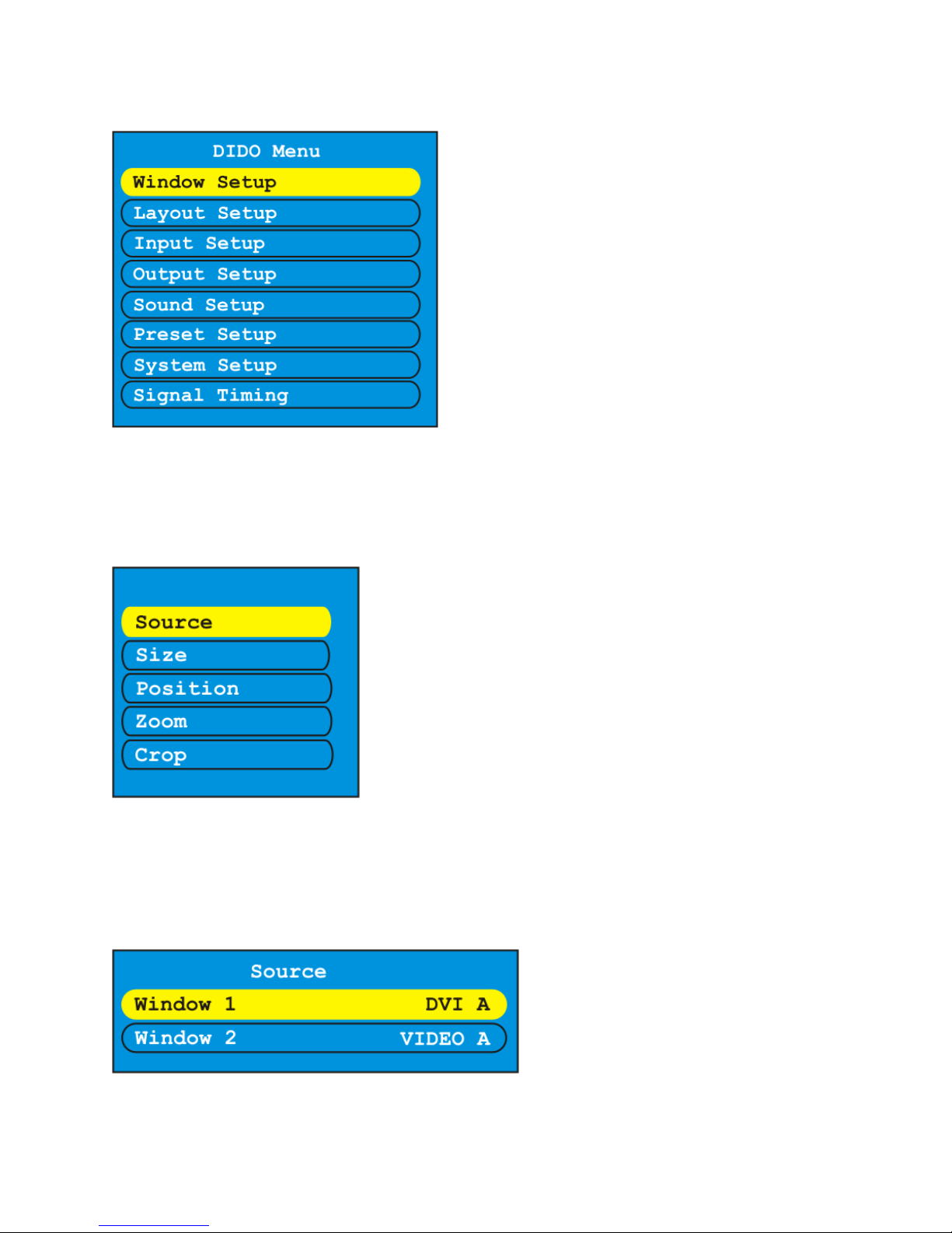
6.2.1 Main Menu
Main Menu contains the branches to all the sub-menus. It is here all the different features can be
accessed.
DIDO Installation Manual
12
6.2.2 Window Setup
This is where source, size, position, zoom, and crop can be modified per window. Once selected the
choice of window for modification will appear. Window Setup effects the characteristics of the window
itself and not the image inside the window.
Source will display the windows available for the layout selected. The example above shows what source
would look like if dual mode is selected. If quad mode was selected then four windows would be
available to select from. The selections per window are DVI A, DVI B, RGB A, RGB B, Video A, and
Video B based on mode. Tri and quad modes have restrictions on which source can be sent to a particular
window. The DIDO will not allow an invalid selection. When in quad mode windows 1 and 2 will show
only Side A sources, windows 3 and 4 will show Side B sources.

DIDO Installation Manual
13
Window size gives the ability to change the horizontal and vertical size of a window. There are 1000
points of accuracy. If the arrow key is pressed once the value will change by tenths of a percent. If an
arrow is pressed and held for 2 or more seconds, the value will change by 1 percent instead of tenths.
Window position gives the ability to change the horizontal and vertical size of a window. There are 1000
points of accuracy. If the arrow key is pressed once the value will change by tenths of a percent. If an
arrow is pressed and held for 2 or more seconds, the value will change by 1 percent instead of tenths.
Window zoom gives the ability to change both the horizontal and vertical size of a window at the same
time to keep the image proportional. There are 1000 points of accuracy. If the arrow key is pressed once
the value will change by tenths of a percent. If an arrow is pressed and held for 2 or more seconds, the
value will change by 1 percent instead of tenths.

DIDO Installation Manual
14
6.2.3 Layout Setup
Layout – Select from Single, PiP, Dual, Tri, and Quad
Rotate – 0, 90, 180, 270
PiP Size – Control the size of the PiP from 0 - 100 percent with accuracy down to the tenths.
PiP Position – Control the size of the PiP from 0 - 100 percent with accuracy down to the tenths.
PiP Transparency – 16 Levels of PiP blending using the up and down arrow keys when in PiP mode.
6.2.4 Output Setup
Output timing for the DVI/RGBHV/YPbPr connector is selected here. The output type is also modified
from this menu for the analog portion of the connector. The choices are RGBHV, RGsB, YPbPr, and No
Output.

DIDO Installation Manual
15
6.2.5 Sound Setup
Volume -- Selects the current (default) volume level
Input -- Selects Side A or B audio input
Mute -- Turns on and off the audio output
Delay -- Enter the amount of audio delay to be added to compensate not just for DIDO
video processing but other equipment as well.
6.2.6 Preset Setup
This menu allows control the saving and loading of up to 99 presets. First select the preset then change to
the preset to be saved or loaded followed by select again. If it is saving the OSD will display the Preset is
being saved.
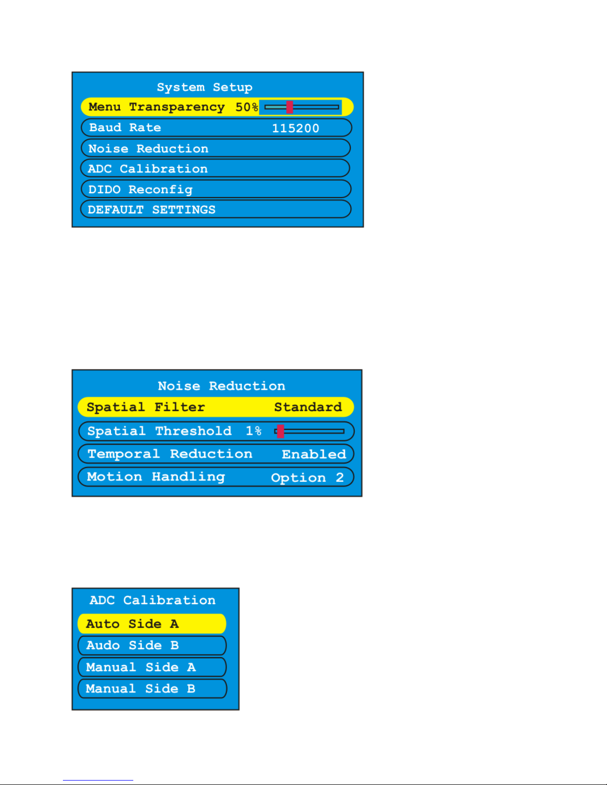
6.2.7 System Settings
This menu allows the selection of restoring defaults, reconfigure (relocks to the source(s)), baud rate,
noise reduction, and OSD Menu Transparency.
DIDO Installation Manual
16
Noise reduction allows the DIDO to clean up an image with random noise. This is useful with sources
that have poor quality. There are 2 types of noise reduction filters available. The first is Spatial which is
good for signals from poor TV reception. The temporal is a good overall noise reduction to clean up an
image. There is a penalty when using noise reduction which is the softening of the image. Best way to
use noise reduction is trial and error to see what works best for the application.
Motion handling is for DIDO’s motion adaptive de-interlacing. There are three options to choose from.
Option 2 gives the best overall compromise of feathering and jitter when enabling this feature. Once
again it is best that you try the different options with the content to see which works best.
ADC Calibration is for the RGBHV inputs color settings. The auto will automatically adjust the gain and
offset for each color when a test pattern is input. The manual allows adjustment to a users liking or with
external color analyzer.

DIDO Installation Manual
17
6.2.8 Signal Timing
This menu allows the adjusting and adding of input and output resolutions. There are currently two user
profiles for custom input and output resolutions. The H Freq and pixel clock is automatically calculated
inside the DIDO and is not necessary for entry. When done making changes select Apply Changes to
save. Keep in mind any changes made effect all inputs using the resolution as well as outputs.
DIDO Installation Manual
18
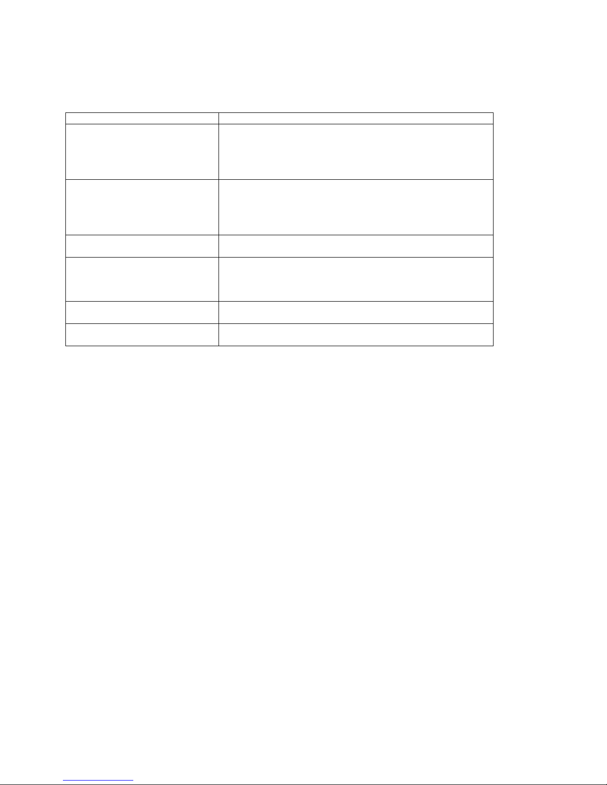
7 Troubleshooting
Symptom Checks
Key on remote is pressed but
nothing happens
Check to see if the batteries are good. If the batteries are
good – check the cable connections between the Plasma
Display and the DIDO. Also, make certain the DIDO has
power.
The display does not turn show
an image
Check to see if the OSD from the DIDO displays. If it does
check the source selection and/or cables for the source. If
there is no OSD then make certain the output cable is
connected properly and the output timing of the DIDO
matches the capabilities of the display device.
No control via RS-232
connection to DIDO
Check cable connection. If connection is ok, check baud
rate and address of DIDO.
DVI output has horizontal noise
going across intermittently
This could happen if a DVI cable is too long. Typical DVI
should not exceed 6ft. Some after market products can
enhance the length of DVI. Please check with their
specifications if it is being used.
Image is green on the input Make certain the DIDO input for RGB/YPbPr is setup
correctly.
Image is green on the output If the output of the DIDO is setup incorrectly (RGBHV vs
YPbPr vs RGsB) it may result in a green image.

DIDO Installation Manual
19
8 Firmware update
The internal software of DIDO (the firmware) can be updated. This may be necessary to fix errors
corrected in the newer releases of the firmware, or to enhance functionality. The serial port of the DIDO
must be connected to the RS-232 (“COM”) port of a PC-compatible personal computer, running MS-
Windows 98, 2k, or XP operating system.
Update procedure
•Create a directory for the DIDO (such as C:\DIDO).
•Save the attached files to the created directory.
•Unzip the files if necessary.
•Open a Win32 (Command Prompt) window (Start ÆRun Æcmd ÆEnter).
•Change to DIDO directory (C:\DIDO).
•Type this command “didoldr.exe 1 dido.did” and press “Enter.” (Note: To change the COM port
use the appropriate comm. port number in place of the 1)
•It will take approximately 20 seconds to finish programming and the device will restart itself.
Example:
“didoldr.exe 1 dido.did”
didoldr.exe is the program loader
1 is the COM port used to program the DIDO (for example, 2 is for COM 2)
dido.did: firmware (this file name can be anything such as dido040916.did)
Microsoft Windows XP [Version 5.1.2600]
(C) Copyright 1985-2001 Microsoft Corp.
C:\DIDO>didoldr.exe 1 dido.did
DIDO firmware loader V2.03 Copyright (c) 2003 Aurora Multimedia
Loading "dido.did"
Opening Com 1... OK
Initiating bootblock..... OK
Initiating load procedure... OK
Transferring image header... OK
Waiting for header response... OK
Erasing flash... OK
Loading flash image (137674 bytes)... 100% OK
Rebooting device...
Warning:
In the event the firmware update is interrupted during the transfer process, cycle the power on the DIDO
and wait 30 sec after reapplying the power to start the transfer process again. The LCD screen may be
blank but that is normal if this should happen.
Please note we have found some USB to RS-232 converters to be unreliable for file transfers of this
nature.
Table of contents
Other Aurora Multimedia DVD Player manuals


