CP650 Installation Manual Installation
2-9
PROFESSIONAL AUDIO
EQUIPMENT 4J06
LISTED
CUS
UL
100 - 240 Vac 50 - 60 Hz 120 W
~
CAUTION
To reduce the risk of fire
replace only with same
type and rating
250V time-lag fuse.
FUSE T 6.3A L
5mmx20mm
Risk of electric shock.
Do not open.
This equipment must be
earthed/grounded.
No user serviceable parts
inside. Refer all service
to qualified personnel.
WARNING
O
San Francisco U.S. Wootton Bassett U.K. ETHERNET
MIC. INPUT
OPTICAL IN 1
OPTICAL IN 2
L
L
R
R
OPTION CARD I/O
READER 1
READER 2
AUTOMATION SERIAL DATA
(RS-232)
MOTOR START
(External Digital Processor)
MAIN AUDIO OUTPUT 6-CH AUDIO INPUT
RL
REMOTES AND AUD. FADER
NONSYNC IN 2
H/I OUTPUT
RL
NONSYNC IN 1
13
1
L
L+
C
C
R
R+
Ls
Ls +
Rs
Rs +
SW
SW +
+
14 17 20 23 24 25
This device complies with Part 15 of the FCC Rules.
Operation is subject to the following two conditions: (1) this
device may not cause harmful interference, and (2) this
device must accept any interference received, including
interference that may cause undesired operation.
This Class A digital apparatus complies with Canadian ICES003.
FADER
REMOTE
+
DATA
IN
N/C
Dolby Digital
MS1
P1
P1/ P2
P2
MS2
13
01
04
05
MUTE
U2
U1
11
10
NONSYNC
1
Digital Cinema Processor
CP650
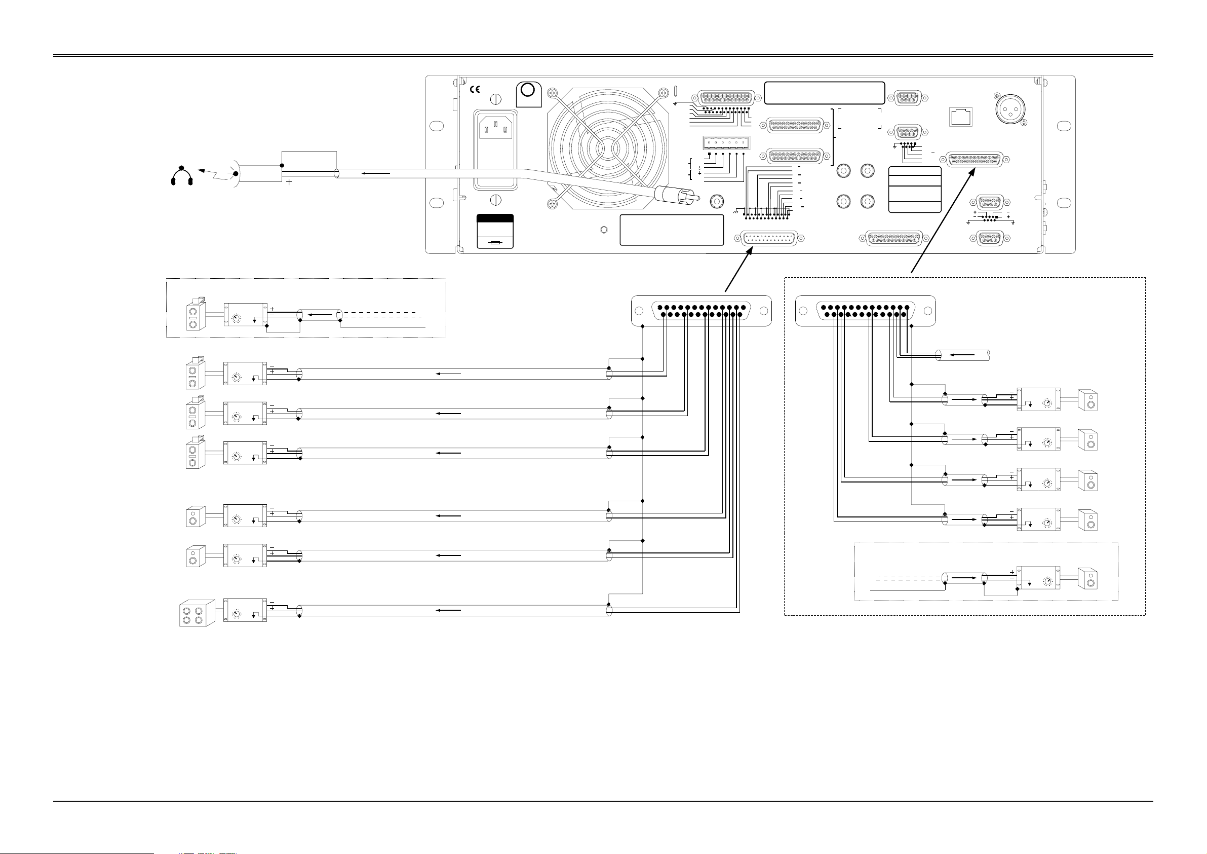
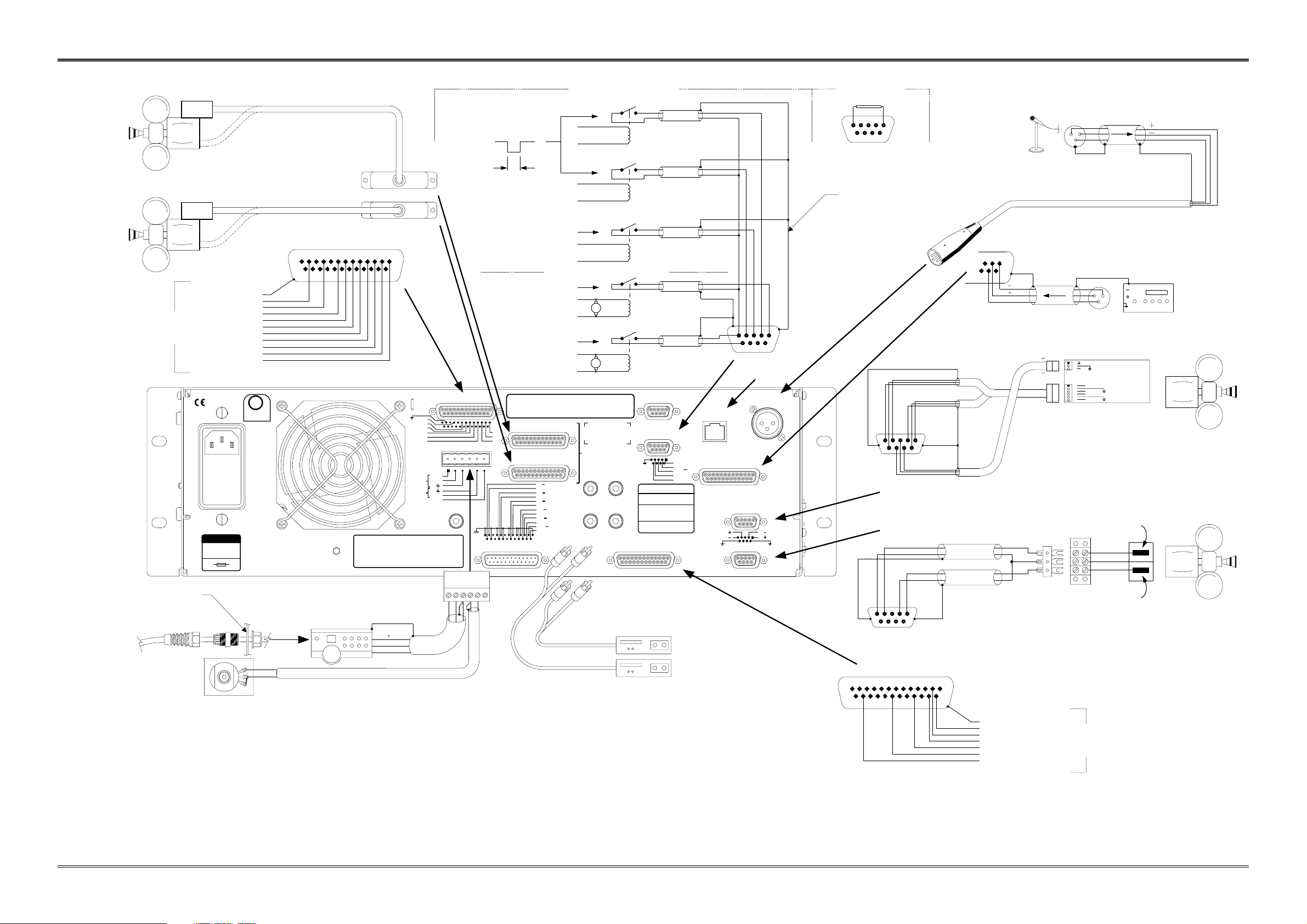
All shields must be connected to the CHASSIS of the CP650.
This achieves the required RF interference immunity. A metal
housing must be used for all D-connectors and the shields
must be connected to the housing. Chassis ground and circuit
(audio) ground are internally connected.
For two conductor with shield wiring, use Belden 8451
2-conductor shielded cable or equivalent: tinned copper,
twisted pair, 22 AWG stranded tinned copper drain wire,
aluminum-polyester shield, 100% shield coverage,
conductor-to-conductor 111 pF per meter.
Follow all local electrical and building codes.
Use grounded (earthed) conduit wherever possible. Avoid
routing signal wiring near electric motors, rectifiers, power
wiring, dimmer wiring, or other sources of electrical noise.
For three conductor with shield wiring, use Belden 8771
3-conductor shielded cable or equivalent: tinned copper,
twisted pair, 22 AWG stranded tinned copper drain wire,
aluminum-polyester shield, 100% shield coverage,
conductor-to-conductor 75 pF per meter.
7
132546
5
6987
43 12 L
R
32
1
96
51
9 786
5 4 23 1
132465321
9
5
6
1
5.
3.
2.
1.
Notes:
4.
Non-Sync 1
Non-Sync 2
CD, Tape, etc.
Front View of Pot
DATA
V
GND
Projector 2
black
red
black
red
green
black
red
black
red
Open
Proj 2 Motor Start Relay
Projector Motor
Projector Motor
Proj 1 Motor Start Relay
OR
Closed
Projector 2
Projector 1
FB425A01.CDR
CP650 INSTALLATION WIRING
INPUT AND CONTROL CONNECTIONS
red
black
red
black
15 V phantom power switchable via front
setup control panel dip switch number 3.
Customer Supplied
100k Linear Pot
Pass wire through strain
relief and chassis access
hole. Tighten inside nut
finger tight.
Cable Part Numbers:
83141 (30 feet) (9.1 meters)
83237 (50 feet) (16.2 meters)
Jumper Plug
(shipped installed on unit)
PA Microphone 1
(Or Mic-multiplexer
for setup)
All shields must be connected
to the metal shield of the D-connector.
Cat. No. 701
Digital Reader
Projector 1
Solar Cell
Reverse Scan / LED
Analog Reader Board
Remote Control Unit Cat. No. 779 or
Remote Fader Cat. No. 771
Projector Changeover Relay
Maintained Closed Contact
Selects Projector 2
Projector Changeover Relays,
Pulsed Contacts
50 ms
minimum
OUT 1 +
OUT 1 -
OUT 2 +
OUT 2 -
J1
J2
1
1
Inboard Digital
Basement Reader
Single Projector2-Projector Changeover
OR:
1
25
13
SHIELD
GROUND
MUTE
U2
U1
11
10
05
04
01
NONSYNC
To Automation
(See Interface Requirements
in Appendix B)
Projector 1
Projector 2
1
25
13
SHIELD
L
Ls
R
C
SW
Rs
6-Channel Analog Input
(all unlabeled pins are signal ground)
(normal operating level = 300 mV)
OR
For Dolby Digital Installations
12
15
red
black
Non-Sync Source
With 2-channel AES/EBU
Digital Output (Format 80)
For future
Automation use
+-
The physical board mounting in the projector and
the connector affect which channel
appears on which pin of the connector.
. The J2 connector pin
solder hole with a square outline is pin 1.
Be aware
that pin allocations for the channels will vary
depending on mounting arrangements of the
board and connector
orientation
32
1