AUSLIFT 915320 User manual

SERVICE
WIRE ROPE INERTIA REEL
PC. 915320, 915321
Lifting Your Business to A Higher Level
1300 100 120
www.austlift.com.au
AUSTRALIAN LIFTING CENTRE PTY LTD

2
ALC SIM 915210/915220/915230_19
SERVICE MANUAL (VOL:4)
www.austlift.com.au
RETRACTABLE INERTIA REEL BLOCK
915320/915321
Plastic Casing Wire Rope Retractable Fall Arrester
Block with integral Rescue Device
Product Code. 915320, 915321
1. ThisServiceManualcontainsstepwiseillustrationsfortheservicingofAUSTLIFT
Retractable Fall Arrest Block.
2. This Service Manual shall be in the custody of only a competent authorized
service personnel, duly endorsed by AUSTLIFT.
3. This Service Manual is meant only to be a handbook for ready reckoning of the
trained service provider for AUSTLIFT Retractable Fall Arrester Block.
4. Once the block has been opened up for servicing by the authorized service
personnel, AUSTLIFT shall not be responsible for any damages/ mishaps
whatsoever. It shall be the duty of the service provider only to respond, to
such a situation.
5. It is extremely important to paste back the original label on to the block casing
after completion of the servicing.
6. Please do not forget to complete the service check card provided along with
the block. This will give easy reference for future use of the block.

3
ALC SIM 915210/915220/915230_19
SERVICE MANUAL (VOL:4)
1300 100 120
RETRACTABLE INERTIA REEL BLOCK
915320/915321
4
14
27
Step Wise Illustrations
Changing The Coil Spring
Standard Torque Values

4
ALC SIM 915210/915220/915230_19
SERVICE MANUAL (VOL:4)
www.austlift.com.au
RETRACTABLE INERTIA REEL BLOCK
915320/915321
STEP 1
STEP 2
1. Place the Block on the Service table with front side up.
2. Ensure that the Allen head of the screw is facing up.
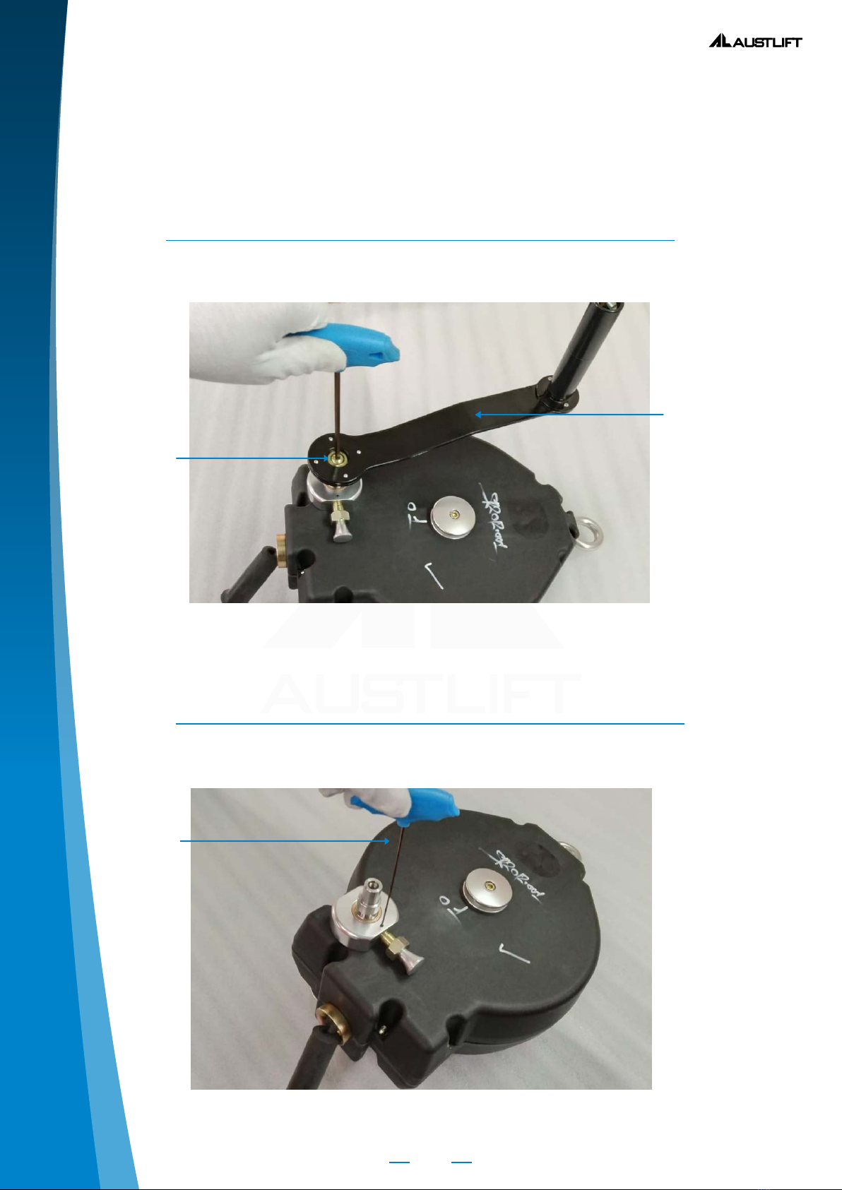
3. Remove the anged head screw with the help of 5 mm allen key and
detach the rescue handle
Open Grub screw M3X5mm. with the help of 1.5mm allen key.
Rescue
Handle
Flanged
head screw
Allen Key

5
ALC SIM 915210/915220/915230_19
SERVICE MANUAL (VOL:4)
1300 100 120
RETRACTABLE INERTIA REEL BLOCK
915320/915321
STEP 3
Open the Push Pin Assembly with help of spanner.
Open the Allen Head main shaft screw and remove the aluminum guide.
Spanner
Push Pin
Assembly
Aluminum
Guide

6
ALC SIM 915210/915220/915230_19
SERVICE MANUAL (VOL:4)
www.austlift.com.au
RETRACTABLE INERTIA REEL BLOCK
915320/915321
STEP 5
STEP 6
Be sure that the Allen Head of the screw is facing up. Remove the 8 screws,
one by one as shown in the gure above.
Now open plane casing.
Caution: While lifting the plain casing, the drum will unwind as you lift
the casing. Slide your hand into the drum to prevent the unwinding of the
drum.
Casing
Screw
Drum
Plain Casing

7
ALC SIM 915210/915220/915230_19
SERVICE MANUAL (VOL:4)
1300 100 120
RETRACTABLE INERTIA REEL BLOCK
915320/915321
STEP 7
STEP 8
Remove the drainage bush from the casing as shown in above gure.
Remove the Pinion Shaft Assembly as shown in above gure.
Pinion Shaft
Assembly
Drum
Drainage
Bush

8
ALC SIM 915210/915220/915230_19
SERVICE MANUAL (VOL:4)
www.austlift.com.au
RETRACTABLE INERTIA REEL BLOCK
915320/915321
STEP 9
STEP 10
Remove the mounting pulley by opening the main shaft screw using 4
mm Allen Key.
Now, take out the wire rope along with the Hook & other metal parts from
the slot of the Ratchet casing by just pulling it up lightly & then release the
tension of the spring by unwinding the drum in anti clock wise direction
as shown in the above g. You will need to unwind approximately 2 to
3 turns, until the drum is completely free of tension. After relieving the
tension, turn the whole assembly upside down.
Direction of
Unwinding
Pulling out the Wire Rope assembly
Main Shaft
Screw

9
ALC SIM 915210/915220/915230_19
SERVICE MANUAL (VOL:4)
1300 100 120
RETRACTABLE INERTIA REEL BLOCK
915320/915321
STEP 11
STEP 12
Remove the Ratchet Casing as shown in the above g.
Try to pull out the Brass Brakes one by one using your ngers to check that
all Brass Brakes are freely moving in and out & the springs pulling them
inwards are not worn or damaged. If not, replace them. Ensure that there is
no friction, whatsoever between the Brass Brakes & the pivot on which they
rotate. The springs should be intact in their position.

10
ALC SIM 915210/915220/915230_19
SERVICE MANUAL (VOL:4)
www.austlift.com.au
RETRACTABLE INERTIA REEL BLOCK
915320/915321
STEP 13
We will now plan to replace the wire rope or other wearable parts of the
Retractable, in case they have been damaged or worn out. Open the 3 Nos
Grub Screw with the help of 2.0mm/1.5mm allen key as shown in gure above.
1. First we will use L-Type Allen key to loosen the grub screw and T-type
Allen key for further opening.
2. While loosening the screws if any screw is not able to loose (stuck into
the hole) then we will not try to apply excessive force on allen, as it will lead
to deform the drive of grub screw.
3. Fix the assembly in Three jaw chuck and with the help of chuck nut
opening gauge try to move the chuck nut anticlockwise for a bit distance
(stop when cuck nut start moving).
4. Now again use L-Type Allen Key and try to loosen the screw, it will get loose
with a ‘click’ sound. Stop and open the grub screw with T-type Allen key.
Hold the assembly in the Three Jaw Chuck as shown.
Open the Chuck Nut by using the Torque Wrench & the Excel Socket as
shown in above gure.
Torque Wrench
3 Nos. Grub Screws to
be opened one by one
Excel Socket
Three Jaw Chuck

11
ALC SIM 915210/915220/915230_19
SERVICE MANUAL (VOL:4)
1300 100 120
RETRACTABLE INERTIA REEL BLOCK
915320/915321
STEP 15
STEP 16
Remove the Chuck Nut.
Remove the Pressure Washer. It is essential to replace this Washer Every
time you service a Retractable. So it would be better to discard it and get
a new one in its place.
Torque Wrench
Pressure Washer

12
ALC SIM 915210/915220/915230_19
SERVICE MANUAL (VOL:4)
www.austlift.com.au
RETRACTABLE INERTIA REEL BLOCK
915320/915321
STEP 17
STEP 18
Pull up the Brake plate and the Friction Plate. Immediately replace the
Friction Plate with a new one.
Lift the Aluminium shim and remove the wire from the slot as shown in
the above g. Aluminium shim should be changed every time you service
a block. Check the entire length of wire for any damages or abrasion marks.
Now assemble it backwards doing the opposite of Step 18, 17, 16, and 15 i e
put back the new Aluminium shim, new friction plate then the brake plate
followed by the new pressure washer and chuck nut.
Aluminium Shim
Wire Rope
Assembly

13
ALC SIM 915210/915220/915230_19
SERVICE MANUAL (VOL:4)
1300 100 120
RETRACTABLE INERTIA REEL BLOCK
915320/915321
STEP 19
STEP 20
It may vary from 500 to 1300 Kgf/cm. It is recommended that we rst tight
chuk nut from minimum value (200) and then check as per step 18 below
to ensure that measured torque is “ As per value indicate in the standard
torque chart.” If not, continue to tighten the chuck nut further by 100Kgf/
cm, each time measuring the achieved torque until the measured value
will be as indicated on standard torque chart.
It should be as per value indicate in the standard torque chart ( Page No. 25).
Ensure that the tightening by Torque Wrench is done as smoothly
as possible without giving any jerks or sudden force till the desired Torque
is reached.
Torque Reading should be as per value
indicate in the standard torque chart.

14
ALC SIM 915210/915220/915230_19
SERVICE MANUAL (VOL:4)
www.austlift.com.au
RETRACTABLE INERTIA REEL BLOCK
915320/915321
STEP 21
Now remove the Circlip Lock ( Retaining Ring) by using the external Circlip
Plier as shown in above gure
Caution : When the Circlip Lock (Retaining Ring) is to be opened, the
spring may bounce back, hence slide your hand in to the cover and open
it very carefully as shown in the above gure.
STEP 22
Remove the spring cover as shown in the above g, ensuring that the
spring is held downwards using your other hand.
Spring Cover
External
Circlip Plier
Circlip Lock
Holding the
Spring down
with your hand

15
ALC SIM 915210/915220/915230_19
SERVICE MANUAL (VOL:4)
1300 100 120
RETRACTABLE INERTIA REEL BLOCK
915320/915321
STEP 23
Quickly put the Safety Bar on the Spring while tightening the Safety Bar
Allen Bolt into the main shaft to prevent the spring from coming out
accidently.
Safety Bar
Allen
Screw
Hold the assembly in the Clamping xture as shown above and Pull out
the wire to check if the spring is broken.
Clamping
Fixture

16
ALC SIM 915210/915220/915230_19
SERVICE MANUAL (VOL:4)
www.austlift.com.au
RETRACTABLE INERTIA REEL BLOCK
915320/915321
STEP 25
STEP 26
After pulling out the wire, put a 15x15x30mm Stopper Block (as shown in
the g.) near to the coil spring screw to create the gap & release the wire
to achieve the rest position of spring.
Caution : Be careful while handling the coil spring.
Hold the spring with the help of a Tool Maker Clamp.
Stopper Block

17
ALC SIM 915210/915220/915230_19
SERVICE MANUAL (VOL:4)
1300 100 120
RETRACTABLE INERTIA REEL BLOCK
915320/915321
STEP 27
STEP 28
Remove the safety bar with the help of 5mm Allen key.
Pull the spring with the help of Tool Maker Clamp.
Allen Key

18
ALC SIM 915210/915220/915230_19
SERVICE MANUAL (VOL:4)
www.austlift.com.au
RETRACTABLE INERTIA REEL BLOCK
915320/915321
STEP 29
Open the coil spring screw nut with the help of 8mm Ring Spanner and
3mm Allen Key as shown above.
STEP 30
Hold the open end of the spring inside the drum and tighten with the help
of screw & nut using 3mm Allen Key. Apply Resi-Quick
Spring Screw Nut
Open End of the Spring

19
ALC SIM 915210/915220/915230_19
SERVICE MANUAL (VOL:4)
1300 100 120
RETRACTABLE INERTIA REEL BLOCK
915320/915321
STEP 31
STEP 32
Put the Coil Spring inside the drum with the help of Tool Maker Clamp and
insert the bend of the spring in to the slot of the shaft.
Immediately put the safety bar & then release the spring
Caution: Be careful while handling the coil spring.
Put the spring cover back as shown in the above g, ensuring that the
spring is held downwards using your other hand.
Holding
the Spring
down with
your hand

20
ALC SIM 915210/915220/915230_19
SERVICE MANUAL (VOL:4)
www.austlift.com.au
RETRACTABLE INERTIA REEL BLOCK
915320/915321
STEP 33
Put the Circlip Lock (Retaining Ring) by using External Circlip Plier and
tighten the 8 Nos of CSK philip head screws of the spring cover one by one.
In case if there is any problem in spring housing assembly.
We could replace the spring housing assembly, by just opening the Allen
head M4 screws X 05Nos. as shown in above g. other wise follow the
below step- 35
CSK Philip Head Screws
External
Circlip Lock
This manual suits for next models
1
Table of contents