Ausmig D260 User manual

M.I.G. Welder
TROUBLE SHOOTING
Symptom Possible Causes & Solution
User Guide
AUSMIG

REVERSE POLARITY
21
DANGER OF
ELECTROCUTION
BEWARE
OF SMOKE
AND STEAM
DO NOT USE NEAR FLAMMABLE
OR EXPLOSIVE MATERIAL
BEWARE OF
RAYS FROM
THE ARC
WARNING
WARNING:Protect yourself and others. Read and understand this manual.
ELECTRIC SHOCK: Can kill.
FUMES AND GASES: Can be dangerous to your health.
ARC RADIATION: Can injure eyes and burn skin.
* Read and understand your employer's safety practices.
* Keep your head out of fumes.
* Use enough natural ventilation, or both, at the
fume source to keep fumes and gases from the breathing zone and
the general area
* Wear correct eye, ear and body protection.
* Do not touch live electrical parts.
* Refer to AS 1674 and WTIA Technical Note 7 or the manufacturer's
recommendations for further information.
* Do not change voltage selection while the torch trigger is depressed.
* Wiring ! Select the correct primary power plug to suit the MIG
purchased.
* Disconnect MIG from power supply prior to servicing machine.
Rev:2.5
*IMPORTANT NOTICE*
AUSMIG MIG welders are covered by a Conditional Warranty.
Some Important Conditions of this Warranty are ;
* The Warranty Card Must Be Filled Out And Returned To The
Manufacturer. (If you do not have a warranty card please contact
your local Distributor.)
* Any UNAUTHORISED Tampering Or Repairs To This Machine Will
Void The Warranty. Repairs To Ausmig MIG Welders Are Only To Be
Performed By The Manufacturer Or Service Agent With Written
Authorisation.
1
CONTENTS
Bottle Mount page 3
Correct Gas
Regulator Assembly
Spool Assembly
Reverse Polarity
Wire Feed Rollers
Gun Assembly page 3
page 17
page 12
page 21
page 15
page 16
page 22
page 13
page 4
page 7
- Steel / Stainless Steel
- Aluminium & Non-Ferrous
Test of Operation
Wire Tension Test
Troubleshooting
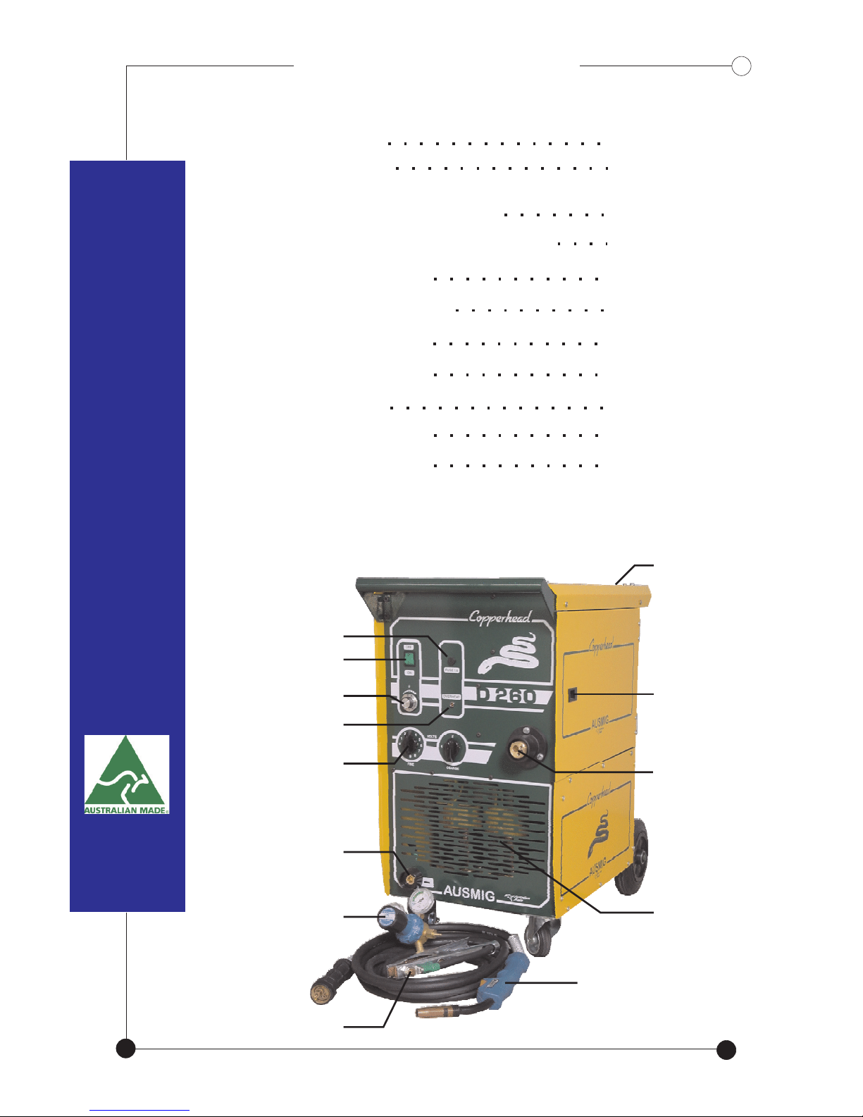
BASIC COMPACT LAYOUTBASIC COMPACT LAYOUT
Typical Control Settings
Fuse 1 Amp Slow Blow
Power Switch
Wire Speed Control
OverHeat Indicator
Votlage Selection
Earth Lead Connection
Gas Regulator
Earth lead & Clamp
MIG Welding Torch
Euro Fitting Torch
Connection
Wire Drive
Compartment
Bottle Holder
Transformer

2
TIP ..
19
BASIC LAYOUT : TRAVELLERBASIC LAYOUT : TRAVELLER
Wire Drive
Compartment
Euro Fitting Torch
Connection
Wire Drive
Hanging Bracket
Wire Speed Control
Remote Wire
Drive
Door Latch
Removable
Mounting Post Bottle Holder
Digital Display
Volts & Amps
Power Source
Transformer
Positive
Connection
8 Metre
Power Cable
Remote Wire
Drive Socket
Power Switch
Overheat Indicator
Fuse 1 Amp
Slow Blow
Voltage Selection
Negative
Connection
Earth Lead
& Clamp
Gas Regulator
MIG Welding Torch
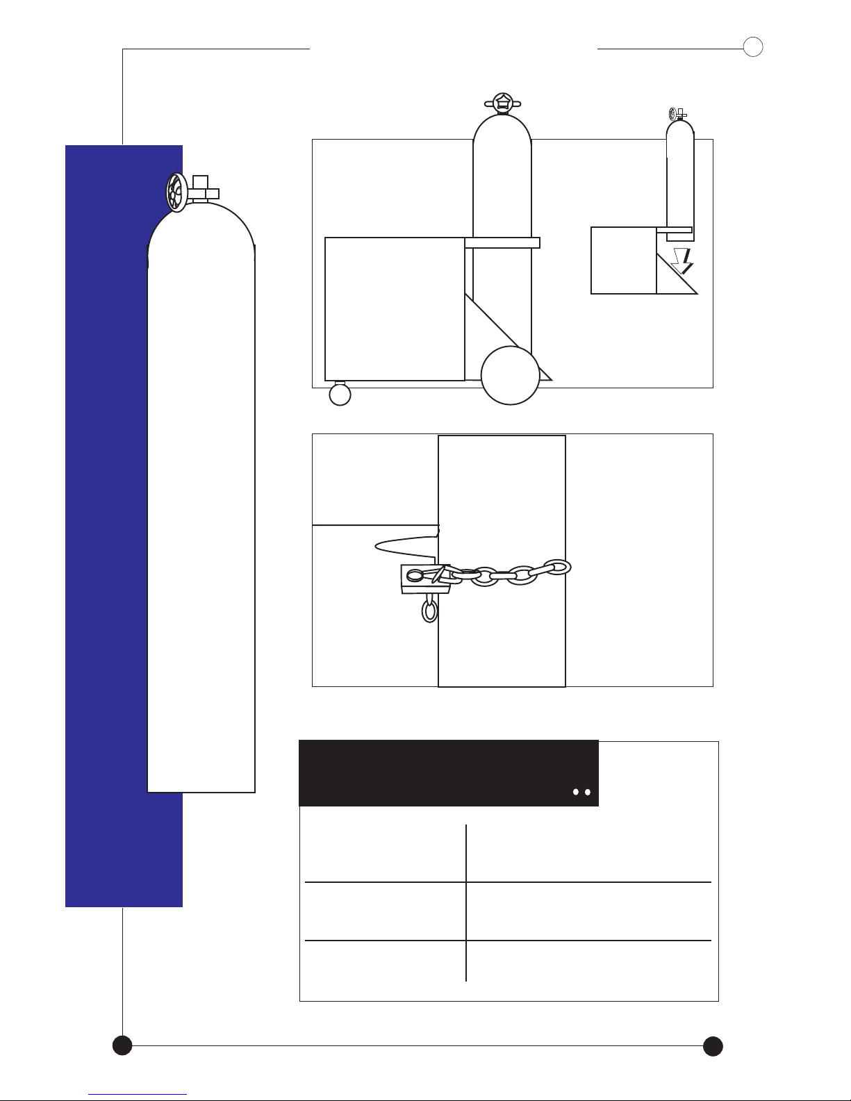
BOTTLE MOUNTBOTTLE MOUNT
Mount the bottle
on the holder
Secure
bottle with
the chain
CORRECT GAS
Stainless Steel
Steel
Aluminium
Argon Shield
Argon Shield
Pure Argon
(ARGON MIX)
(ARGON MIX)
Do not drop the bottle
onto the machine
3

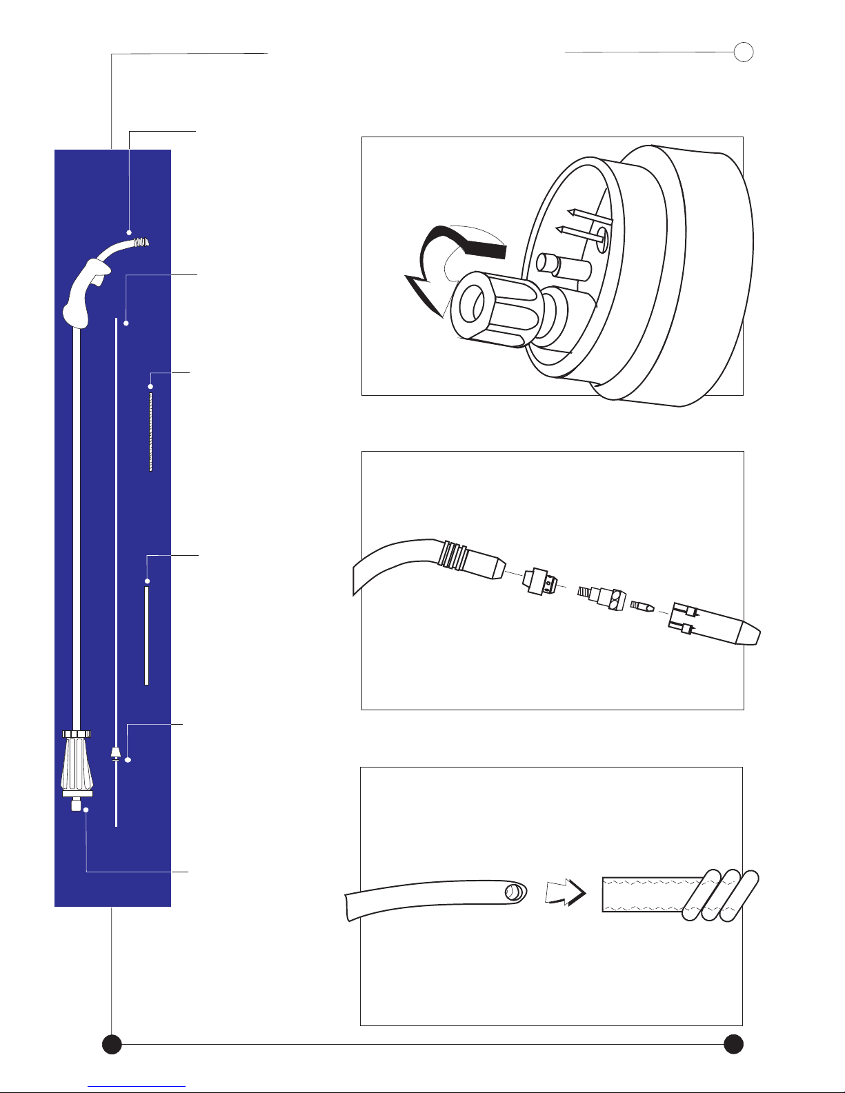
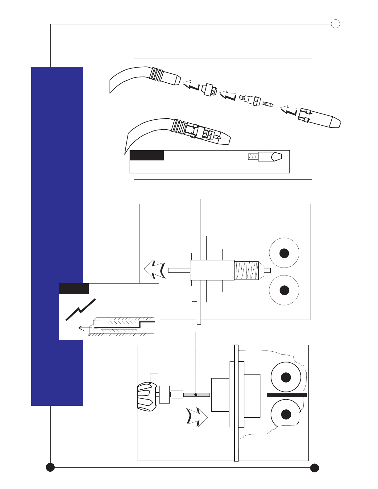
GUN ASSEMBLY
- For Steel / Stainless Steel
GUN ASSEMBLY
-For Steel / Stainless Steel
liner (A)
torch
Check
for
any
kinks
Remove liner
positioning
nut.. *A*
Lay gun and
liner straight
REGULATOR ASSEMBLY
4
LINER
Ensure that the correct
tip is fitted for the
wire being used.
17
Disassemble
torch head..
Unscrew
Pull out
A
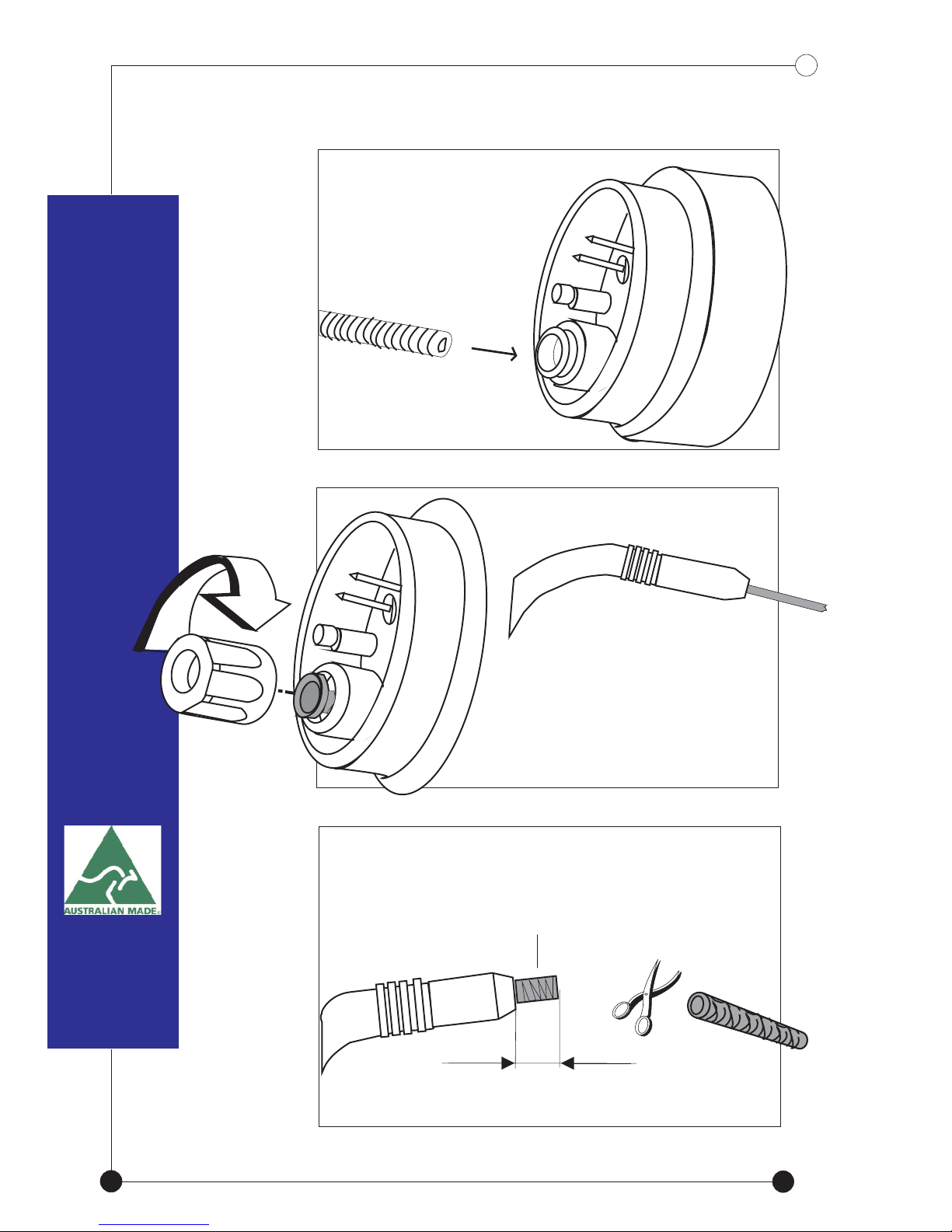
liner.
2mm
Cut excess liner leaving
2mm from the gun neck
Screw positioning
nut back tightly but
over tension.DO NOT
GENTLY feed
liner fully through
the euro fitting of
the torch
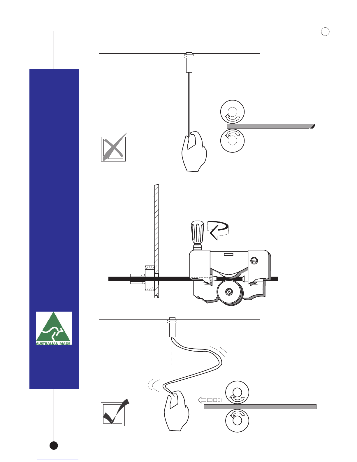
WIRE TENSION TEST
5

Re -assemble
torch head
Slide nozzle on firmly
Euro fitting
*Slide Together*
Do not
allow the
guide tube
to touch
rollers.
Leave 2mm
gap between
the two.
6
Align the torch
and Euro Fitting.
Screw in the collar
until it “bottoms”.
Do not overtighten
Startup Procedure
15
TORCH
TEFLON
LINER (A)
BRASS
NECK
LINER
BRASS
TUBE
SECURING
COLLET
LINER
POSITIONING
NUT
A
Teflon
liner (A)
Screw liner into brass spring
neck tightly on the opposite
end from the securing collet
Unscrew liner
positioning
nut (E)
Disassemble
torch head
GUN ASSEMBLY
- For Aluminium & Non-Ferrous
GUN ASSEMBLY
- For Aluminium & Non-Ferrous
Brass spring
neck liner (B)
(B)
(C)
(D)
(E)
Lay gun and liner
out straight
Remove steel
liner if fitted
7

WIRE FEED ROLLERS
NOTE
GENTLY feed the
connected insert
fully through until
2mm is
protruding from
the gun head
Slide securing
collet & washer (D)
through to the end of the euro fitting
Screw back positioning
nut (E) through the liner
*Do Not Overtighten*
DO NOT CUT
EXCESS LINER YET!!
2mm
(B)
813
WIRE SPOOL ASSEMBLY Remove steel guide
tube from feed roller
TIP.. use a piece of mig
wire to hook and
remove steel guide
tube
TORCH
TEFLON
LINER (A)
Connect euro fitting
to mig machine
Re -assemble
torch head
NOTE
You MUST use aluminium contact tip
ALUM
9
TOGGLE SWITCH

2mm
Cut excess liner ensuring a
2mm space is left
between roller and liner
Remove torch to align
brass tube
LINER
Using a hacksaw, cut brass
tube (C) to exactly the same length
as the protruding liner
10 11

Reconnect
euro fitting
to mig machine
Check that 2mm gap is between
the liner and the roller. DO NOT
let them touch.
2mm
Slide the brass tube over the
liner until 2 mm of the
liner protrudes from the neck
11
Ensure a “U”
Groove Roller
is fitted.
* Do not overtighten*
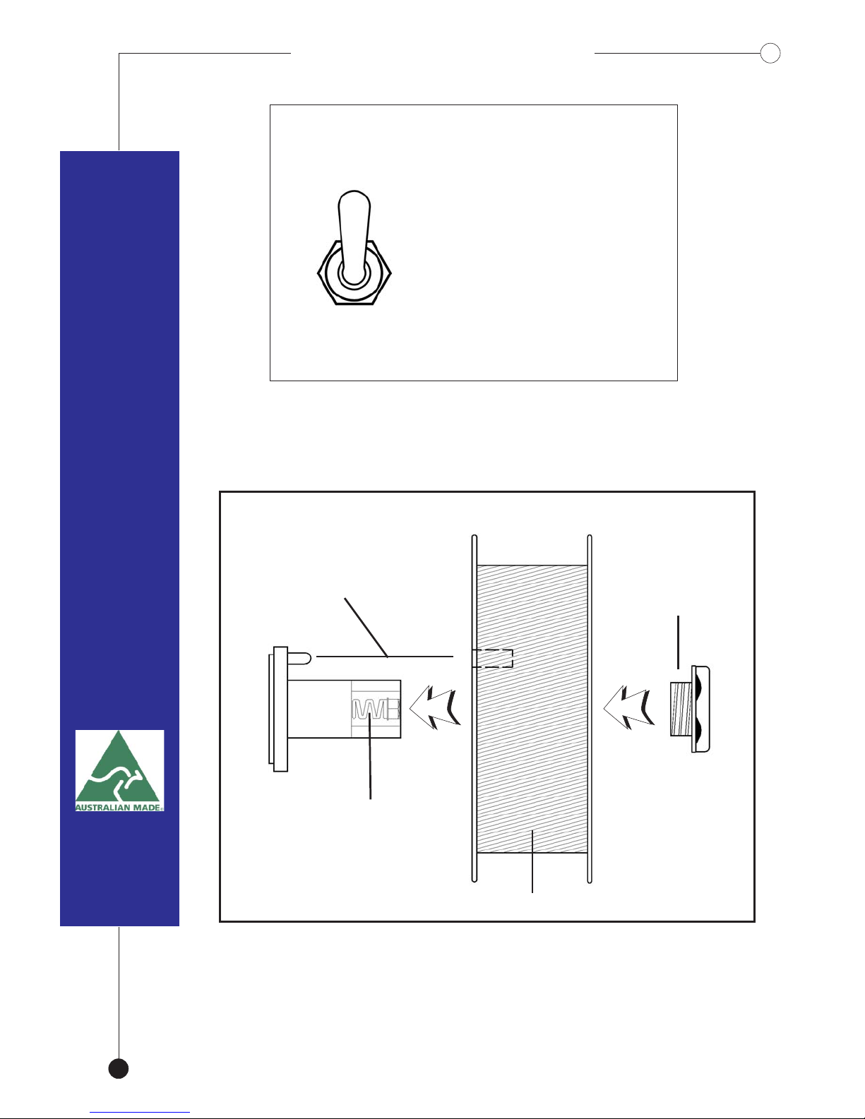
WIRE SPOOL ASSEMBLYWIRE SPOOL ASSEMBLY
TIP..
12
NOTE
9
TOGGLE SWITCHTOGGLE SWITCH
Steel
Alum
Select the appropriate
wire speed for your
application.
Slow speed for Steel.
Fast for Aluminium.
The Switch is located
on the back of the unit.
15 Kg Wire Spool
Spool hub
Adjustment
Locking Nut
Locating Pin
When fitting a spool of wire, ensure that the
locating lug is correctly aligned with the spool.
Do not overtighten the locking nut.
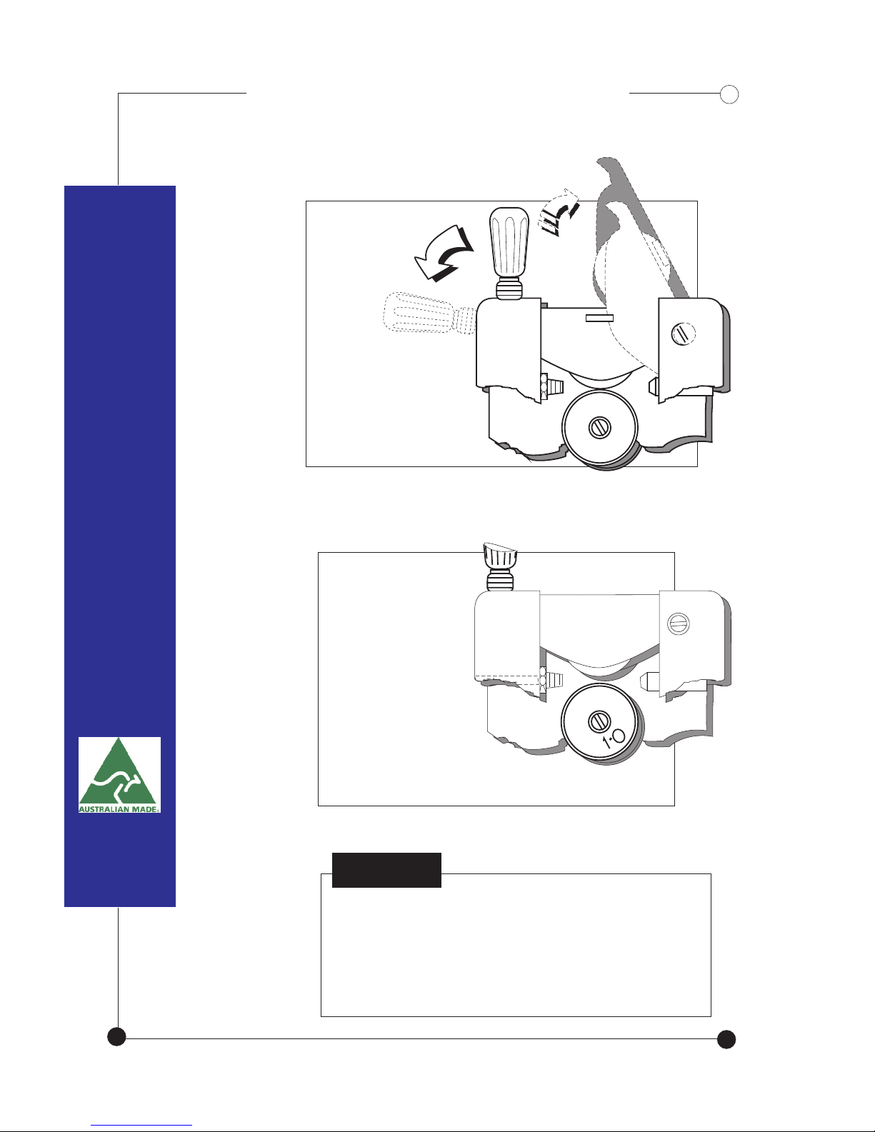
Release
Wire-Drive
Tensioner
WIRE FEED ROLLERSWIRE FEED ROLLERS
NOTE
Liners should be blown through with
compressed air every time a roll of
wire is replaced .
Install the
appropriate
drive roller to
match the selected wire.
13

A
GUN ASSEMBLY
- For Aluminium & Non-Ferrous
Feed wire through
until it is 30mm
into the guide tube
8
14 7
Return roller 1
then tensioner 2
1
2
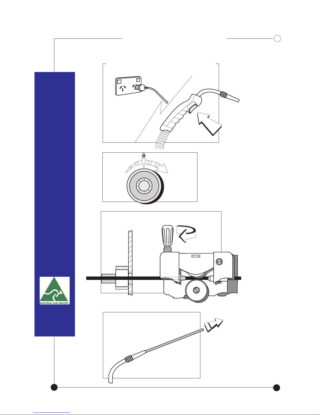
Startup ProcedureStartup Procedure
Keep trigger depressed
until wire protrudes out
from the gun head at
approximately 300mm
Twist tensioner until wire begins
to roll through
Plug into mains, switch machine on
Depress &hold trigger down
Adjust wire
speed control
knob to start
wire drive rollers
12
3
4
5
6
9
87
15
16
Twist tensioner
accordingly.
If wire slips
through the
rollers.. Not
enough tension
No wire
movement..
Gun head
Wire sways
and runs
through the
rollers without
slipping
Hold wire
WIRE TENSION TEST
Continuous
feed..
16
5
3 ~ 3.5 Maximum
Check setup if more
is required.

GUN ASSEMBLY
- For Steel / Stainless Steel
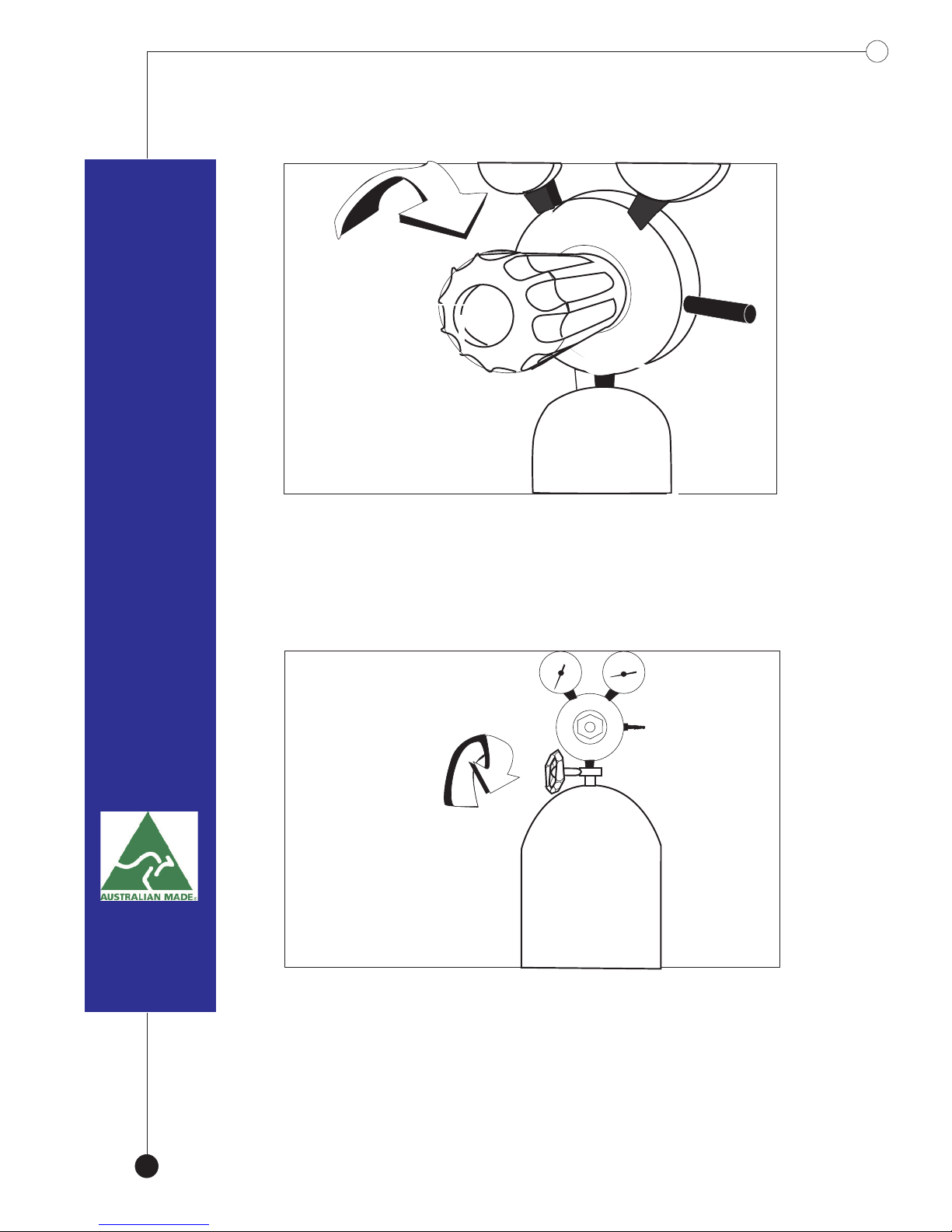
REGULATOR ASSEMBLY
Screw regulator
onto gas bottle
17
Screw nut & tail
with gas hose connected
to the regulator.
Remaining gas
Flow rate.
Gas Outlet.
BOTTLE MOUNT
CORRECT GAS
Slowly open the gas bottle valve.
18 3
Screw in pressure adjustment knob
until slight resistance is felt.
This manual suits for next models
1
Table of contents
Popular Welding System manuals by other brands


EWM
EWM PICO 230 CEL operating instructions

Xcel-Arc
Xcel-Arc RAZORWELD MIG200 operating manual

Harbor Freight Tools
Harbor Freight Tools VULCAN MIG GUN LINER Owner's manual & safety instructions

DINSEO
DINSEO DIX GO 1206.M Operation manual

Lincoln Electric
Lincoln Electric Vernon Tool MasterPipe Compact Profiler Operator's guide

Lincoln Electric
Lincoln Electric STT-10 HEAD & CONTROLS BOOM MOUNT OR BENCH MODELS... Operator's manual


