manuals.online logo
Brands
  1. Home
  2. •
  3. Brands
  4. •
  5. Phoenix
  6. •
  7. Welding System
  8. •
  9. Phoenix DryRod TYPE 50A SERIES User manual

Phoenix DryRod TYPE 50A SERIES User manual

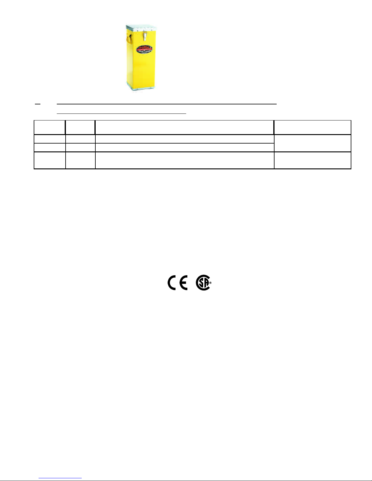
I. OPERATING INSTRUCTIONS FOR TYPE 50A SERIES
MODELS 7, 9, 10, 11, 14, 15, & 17 PORTABLE ELECTRODE STABILIZATION OVENS
*Caution* - To avoid oven damage, never place oven in contact with welding current.
N5430400P-1
**CAUTION**
All wiring should be done by licensed electricians in accordance with State & Local codes plus NEC (National Electric
Code) Standards. Improper installation or use may result in serious injury. Always remove oven from power source
before troubleshooting or repairing.
II. TROUBLESHOOTING - TYPE 50 OVENS
OVEN FAILS TO OPERATE - NO HEAT
1. If oven will not heat, check power supply.
2. Check plug at outer end of power cord. Check com-
plete power cord for continuity. If defective, replace cord
assembly.
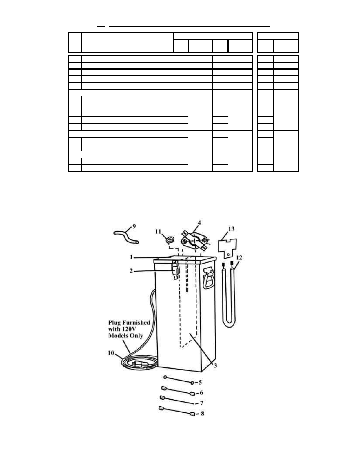
3. Disconnect wires from heating element and check
heating element for continuity (access through top of
oven). If defective, replace elements.
4. On type 50A ovens check thermostat for continuity at
ambient temperature (access through top of oven). If
defective, replace thermostat.
OVEN OPERATES - OVERHEATS
1. Check thermostat operation as in number 5 (Oven
Fails To Operate - No Heat).
DryRod
Electrode Stabilizing
Ovens
®
Type 50A Model, 9, 10, 11, 14, & 17 120V (AC/DC)
Plug power cord into suitable 120 Volt AC or DC power
source.
Type 50A Model 7 & 15, 240V (AC Only)
Plug power cord into suitable 240 Volt AC (Only) power
source.*
ELECTRODE HOLDING
1. Open lid of box and allow approximately 20 minutes
warm-up to drive out any retained moisture.
2. Place only dry electrodes within box. Keep lid closed
but unlatched while plugged into powered receptacle.
ELECTRODE STORAGE
3. When your job is done, the oven should remain con-
nected to its power source. If it becomes necessary to
disconnect from power, keep the lid closed and latched
to provide sealed storage of unused electrodes.
4. Your DryRod® oven has been preset at the factory for
optimum temperature control. The sealed thermostat is
not adjustable, but easily replaced if it fails. Average
stabilized temperature of the oven is 300°F with a full
load (average 250°F empty). A parts list and wiring dia-
grams are printed on the reverse side for your conven-
ience.
*Warranty is void if used with D.C. power source
TYPE 50A MODEL 15
Three Wire Grounded Circuit:
240 Volts AC (Only) *
Temperature: 300°F Average
(stabilized temperature)
Heating Element: Ring Type, 350 Watts, 240 Volts
TYPE 50A MODEL 14
Three Wire Grounded Circuit:
120 Volts AC/DC
Temperature: 300°F Average
(stabilized temperature)
Heating Element: Ring Type, 350 Watts, 120 Volts
N5430400N-2
III. TYPE 50A REPAIR PARTS ILLUSTRATION
Item
No. Description 120V 240V
AC Only
AC Only
1Lid Assembly 1NLA 1NLA
1A Lid Gasket (not shown) 1NLA 1NLA
2Pull Catch Loop 17201400 17201400
3Compartment Divider 22601000 22601000
4Heating Element 14402200 14401700
5Heating Element Clamp Assembly 1NLA 1NLA
6Thermostat Kit 11257061 11257061
Wire Assembly (2 ring terminals) - -
7Wire Assembly (2 female terminals) 1 1
Wire Assembly (female terminal) - -
Wire Assembly (2 female terminals) - -
Fiberglass Sleeve 1.25 Ft. 1 1
8Cord with Plug, remove plug for 240V 1-
9Strain Relief Bushing (7P-2) 1 1
10 Gasket Plate 1 1
11 Gasket 1 1
Part Numbers
Lead Kit includes material to make:
Qty/
Oven
Cord Kit Includes 1257122 1257122
Qty/
Oven
1257123 1257123
Gasket Kit Includes NLA NLA
50A WIRING DIAGRAM 50A 240V WIRING DIAGRAM
Phoenix International, Inc.
8711 West Port Avenue
Milwaukee, WI 53224 USA
Phone (414) 973-3400
Fax (414) 973-3210
www.phx-international.com
[email protected]
Phoenix International, Inc. warrants its products against defects in material and workman-
ship. The company will, at its discretion, repair or replace any properly installed Phoenix
International manufactured product which fails under normal operating conditions within
one year from date of receipt. Contact the factory for return authorization before returning
the product to Phoenix International freight prepaid. If our inspection confirms that the
product is defective under terms of this warranty, it will be repaired/ replaced and returned
freight prepaid.
This warranty applies only to Products sold by Phoenix International, Inc. and specifical-
ly excludes installation or de-installation labor, transportation, or equipment of another
manufacturer used in conjunction with Phoenix International products. No other warranty,
expressed or implied, exists beyond this warranty declaration.
Phoenix constantly strives to improve its products and therefore reserves the right to
change design, materials, and specifications without notice.
WHEN ORDERING, SPECIFY PART NUM-
BER, DESCRIPTION, QUANTITY AND THE
FOLLOWING NAMEPLATE DATA: "TYPE,
MODEL NO. AND VOLTAGE".
11
10
I. OPERATING INSTRUCTIONS FOR TYPE 50 SERIES PORTABLE
ELECTRODE STABILIZATION OVENS
Type Part #Description - (All 50-60 cycles) Temp. Range**
50B/120 1205410 120V AC* @ 350 watts w/ 10' Grounded HD cord
50B/240 1205411 240V AC* @ 350 watts w/ 10' Grounded HD cord, no plug
50C/120 1205420 120V AC/DC @ 200 watts w/ 10' Grounded HD cord 300°F (149°C) Constant
Input, No Thermostat
300°F (149°C) Preset
Sealed Thermostat
*Caution* - To avoid oven damage, never place oven in contact with welding current.
N5610244D-1
**Average Stabilized Temperature @ 70°F Ambient Temperature
*Operation on Direct Current will damage oven and void warranty
DryRod
Electrode Stabilizing
Ovens
®
Electrode Stabilization Ovens General Information:
Insulation: 1" (2.5cm) Glass Fiber Batt
Chamber Size: 6" x 6" x 18" (15 x 15 x 46cm)
Capacity: 50 lb. (22.7kg) of 18" (45.7cm) electrodes also accepts 10"
(25.4cm), 12" (30.5cm), & 14" (36cm)
Net Weight & Dimensions: 9" x 9" x 21" (22 x 24 x 54cm) 29 lbs. (13Kg)
Ship Weight & Dimensions: 10" x 10" x 24" (25 x 25 x 54cm) 32 lbs.
(14.5Kg)
Wiring
Check type and voltage on nameplate.
Types 50B 120/240V AC only models utilize a tamperproof
sealed thermostat, providing a 300°F average stabilized load
temperature.
Type 50C/120V AC/CD (Non-Thermostat model), utilizes
constant heat input, providing a 300°F average stabilized
load temperature.
Note: All current 50B ovens rated at 120 volts have a Model
1 designation, 240 volt ovens have Model 2 designation.
Grounding
1. The 120 volt ovens have a three blade plug cap with
grounding prong (NEMA 5-15P) attached to a 10 foot power
supply cord. When used with a grounded receptacle, these
ovens meet all local electrical code requirements and are
U.L. Listed.
2. The 240 volt ovens have a 10 foot power supply cord.
When used with a grounding plug cap and a grounded
receptacle, these ovens meet all local code requirements.
Electrode Holding
1. Open lid of oven and allow approximately 20 minutes
warm-up time to drive out any retained moisture.
2. Place only dry electrodes within oven. Keep lid closed but
unlatched while plugged into power receptacle.
Electrode Storage
These ovens are not to be used for rebaking or recondition
-
ing contaminated electrodes. They are designed to accept
electrodes in 100% useable condition and to maintain that
condition until consumed at the job site. For optimum stabi
-
lization, oven should be hot when loaded and kept “on line”
as long as electrodes are being stored.
Type 50 series ovens are not airtight and electrodes stored
within will start absorbing ambient moisture as soon as the
oven cools. We recommend removal of electrodes at shift
end and storage of same consumables in suitable larger
holding ovens until reissued.
Guide to Storage
In the absence of detailed storage information from your
electrode manufacturer, the "Revised Guide To Electrode
Storage" (available from Phoenix International, Inc.) may be
used as an indication of approximate temperatures for use
of the oven. For Specific information involving critical oper
-
ations be sure to contact your electrode manufacturer for
complete information.
II. OVEN TYPE DESCRIPTION
N5610244D-3
**CAUTION**
All wiring should be done by licensed electricians in accordance with local codes. Improper installation or use may
result in serious injury. Always remove oven from power source before troubleshooting or repairing.
III. TROUBLESHOOTING - TYPE 50 OVENS
OVEN FAILS TO OPERATE - NO HEAT
1. If oven will not heat, check power supply.
2. Check plug at outer end of power cord. Check complete
power cord for continuity. If defective, replace cord assem-
bly.
3. Disconnect wires from heating elements and check heat-
ing element for continuity (access through top of oven). If
defective, replace elements.
4. On type 50B ovens check thermostat for continuity at
ambient temperature (access through top of oven). If defec
-
tive, replace thermostat.
OVEN OPERATES - OVERHEATS
1. Check thermostat operation as in number 5 (Oven Fails
To Operate - No Heat).
Thermostat
Thermostat
Heating
Elements White
Power
Lead Black
Power
Lead Green
Ground
Lead
Heating
Elements White
Power
LeadBlack
Power
Lead Green
Ground
Lead
Heating
Elements White
Power
Lead Black
Power
Lead Green
Ground
Lead
50B WIRING DIAGRAM 50B 240V WIRING DIAGRAM
50C 120V WIRING DIAGRAM
N5610244D-5
IV. TYPE 50B & 50C REPAIR PARTS ILLUSTRATION
Note
Always replace BOTH heating elements if one fails. (Two are required for each oven.)
Replacement elements are sold in sets of (2) each only.
N5610244D-7
Item
No. Description 120V 240V 50C/120V
AC Only
AC Only
AC/DC
1Lid Assembly 1NLA 1NLA 1NLA
1A Lid Gasket (not shown) 1NLA 1NLA 1NLA
2Pull Catch Loop 1 7201400 1 7201400 17201400
3Compartment Divider 2 2601000 2 2601000 22601000
4Thermostat Kit 1 1257061 1 1257061 - -
5Wire Assembly (2 ring terminals) 1 1 1
6Wire Assembly (2 female terminals) -1-
7Wire Assembly (female terminal) 5 1 4
8Wire Assembly (2 female terminals) -1-
9Fiberglass Sleeve 1.25 Ft. 1 1 1
10 Cord with Plug, remove plug for 240V 1-1
11 Strain Relief Bushing (7P-2) 1 1 1
12 Heating Element 2 2 2
13 Insulating Shield 2 2 2
1257123
1257120
NLA NLA NLA
1257120 1257120
Qty/
Oven
Qty/
Oven
1257123 1257123
Part Numbers
Heating Element Kit Includes
Lead Kit includes material to make:
Qty/
Oven
Cord Kit Includes
Phoenix International, Inc. •8711 West Port Avenue • Milwaukee, WI 53224 USA
Phone (414) 973-3400 • Fax (414) 973-3210 • www.phx-international.com • [email protected]
Phoenix International, Inc.
8711 West Port Avenue
Milwaukee, WI 53224 USA
Phoenix International, Inc. warrants its products against defects in material and
workmanship. The company will, at its discretion, repair or replace any prop-
erly installed Phoenix International manufactured product which fails under
normal operating conditions within one year from date of receipt. Contact the
factory for return authorization before returning the product to Phoenix
International freight prepaid. If our inspection confirms that the product is
defective under terms of this warranty, it will be repaired/ replaced and returned
freight prepaid.
This warranty applies only to Products sold by Phoenix International, Inc. and
specifically excludes installation or de-installation labor, transportation, or
equipment of another manufacturer used in conjunction with Phoenix
International products. No other warranty, expressed or implied, exists beyond
this warranty declaration.
Phoenix constantly strives to improve its products and therefore reserves the
right to change design, materials, and specifications without notice.
Following quantities for each oven:*
• One heating element kit, No. 1257020 (Type 50B 120 &
240 volt models)
• One heating element kit, No. 1257071 (Type 50C 120 volt
models)
• One thermostat kit, No. 1257061 (Type 50B 120 & 240 volt
models)
• One (1) 10 foot connection cord with cap & strain relief, No.
1257120 (120 & 240 volt models).
V. SUGGESTED SPARE PARTS TYPE 50B & 50C OVENS
*For quantities of ovens exceeding 10, we suggest providing approximately 20% more of the above quantities of spares as sufficient for day to day
operation.
For overseas operation we suggest a minimum of 30% more for spares.
Phone (414) 973-3400
Fax (414) 973-3210
www.phx-international.com
[email protected]
N5610244D-9

This manual suits for next models

7

Popular Welding System manuals by other brands

Hypertherm Powermax125 Operator's manual

Hypertherm

Hypertherm Powermax125 Operator's manual

GÜDE GC 140 instructions

GÜDE

GÜDE GC 140 instructions

STAMOS S-MMA 200 LT user manual

STAMOS

STAMOS S-MMA 200 LT user manual

IMS 200E FV manual

IMS

IMS 200E FV manual

SFS intec isoweld 3000 Series operating instructions

SFS intec

SFS intec isoweld 3000 Series operating instructions

Amada ML-2450A-CE Operation manual

Amada

Amada ML-2450A-CE Operation manual

Thermal Arc 6045 EXCEL-ARC operating manual

Thermal Arc

Thermal Arc 6045 EXCEL-ARC operating manual

Nelson NS20A Instruction and maintenance manual

Nelson

Nelson NS20A Instruction and maintenance manual

Lincoln Idealarc AC-250 operating manual

Lincoln

Lincoln Idealarc AC-250 operating manual

Amada HF28/240 Operation manual

Amada

Amada HF28/240 Operation manual

Cebora POWER PLASMA 3100 Service manual

Cebora

Cebora POWER PLASMA 3100 Service manual

Lincoln Electric INVERTEC CC400-T Operator's manual

Lincoln Electric

Lincoln Electric INVERTEC CC400-T Operator's manual

ESAB MobileFeed 300 AVS instruction manual

ESAB

ESAB MobileFeed 300 AVS instruction manual

Hypertherm HyPerformance Plasma HPR800XD instruction manual

Hypertherm

Hypertherm HyPerformance Plasma HPR800XD instruction manual

P.I.T. PMIG145-C1 instruction manual

P.I.T.

P.I.T. PMIG145-C1 instruction manual

G.I.KRAFT GI12117 user manual

G.I.KRAFT

G.I.KRAFT GI12117 user manual

ESAB Caddy Arc 201i instruction manual

ESAB

ESAB Caddy Arc 201i instruction manual

Strata ADVANCEMIG 250 operating instructions

Strata

Strata ADVANCEMIG 250 operating instructions

manuals.online logo
manuals.online logoBrands
  • About & Mission
  • Contact us
  • Privacy Policy
  • Terms and Conditions

Copyright 2025 Manuals.Online. All Rights Reserved.