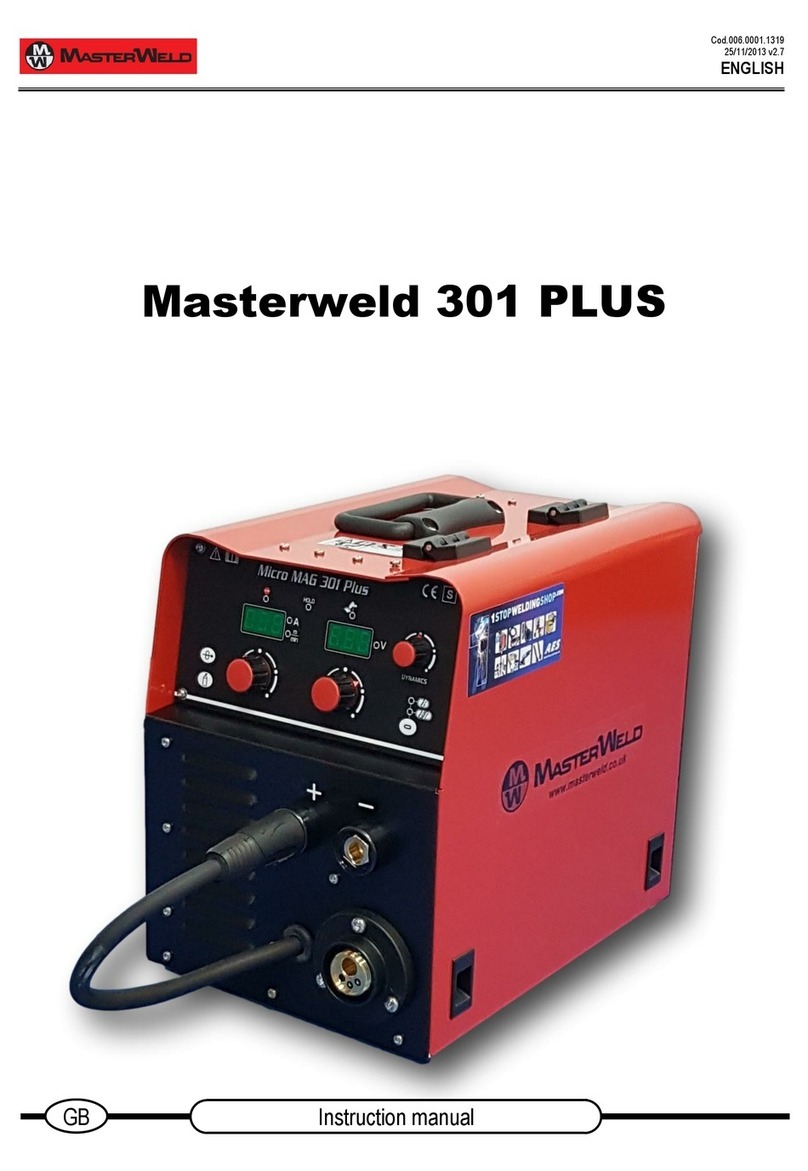
Masterweld 200AC/DC User manual

Nov 2022
2
25
5
1
19
9
7
7
1
13
3
1
1
I
IT
T
G
GB
B
F
FR
R
E
ES
S
D
DE
E
B
Be
ed
di
ie
en
nu
un
ng
gs
sa
an
nl
le
ei
it
tu
un
ng
g
M
Ma
an
nu
ua
al
l
d
de
e
i
in
ns
st
tr
ru
uc
cc
ci
io
on
ne
es
s
I
In
ns
st
tr
ru
uc
ct
ti
io
on
n
m
ma
an
nu
ua
al
l
M
Ma
an
nu
ue
el
l
d
d’
’i
in
ns
st
tr
ru
uc
ct
ti
io
on
n
M
Ma
an
nu
ua
al
le
e d
d’
’i
is
st
tr
ru
uz
zi
io
on
ni
i
2
20
00
0A
AC
C/
/D
DC
C
MASTERWELD 200 AC/DC9_20/06/2012

Nov 2022
DICHIARAZIONE DI CONFORMITÁ
DECLARATION OF CONFORMITY
DECLARATION DE CONFORMITE
DECLARACION DE CONFORMIDAD
KONFORMITATSERKLARUNG
Si dichiara che l’apparecchio tipo
We hereby state that the machine type
On déclare que la machine type
Se declara que el aparato tipo
Die Maschine Typ
MASTERWELD 200 AC/DC
s.n.:
è conforme alle direttive
is in compliance with the directives
est conforme aux directives
es conforme a las directivas
entspricht den Richtlinien
2004/108/CE
2006/95/CE
2011/65/EU
e che sono state applicate le norme
and that the following standards apply
et qu’on a appliqué le normes
y que se han aplicado la normas
folgende Normen kamen zur Anwendung
EN 60974-1
EN 60974-3
EN 60974-10
Ultime due cifre dell’anno di affissione marcatura CE:
Last two digits of the year CE marking:
Deux derniers chiffres de l'année d'affichage marquage CE:
Últimas dos cifras del año de obtención de la marca CE:
Letzte zwei Ziffern der Jahreszahl der Anbringung der EG-
Kennzeichnung:
13
OGNI INTERVENTO NON AUTORIZZATO DA MASTERWELD. FARÁ DECADERE QUESTA DICHIARAZIONE
ANY TAMPERING OR CHANGE UNAUTHORIZED BY MASTERWELD SHALL IMMEDIATELY INVALIDATE THIS STATEMENT
TOUTE MODIFICATION APPORTEE A LA MACHINE SANS L’AUTORISATION DE MASTERWELD ANNULERA CETTE DECLARATION
TODA MODIFICACIÓN DE LA MAQUINA SIN LA AUTORIZACIÓN DE MASTERWELD INVALIDARA ESTA DECLARACIÓN
JEDE VERÄNDERUNG DER MACHINE OHNE GENEHMIGUNG DER FIRMA MASTERWELD ANNULLIERT DIESE ERKLÄRUNG

−Prima di installare e utilizzare l’apparecchiatura
leggere le norme di sicurezza allegate al prodotto!
−Before installing and using the equipment read the
safety rules attached to it!
−Avant d’installer et d’utiliser l’appareillage, lisez
les normes de sécurité jointes au produit !
−Antes de instalar y utilizar la maquinaria, ¡leer las
normas de seguridad que se adjuntan al producto!
−Lesen Sie vor der Installation und dem Gebrauch
des Geräts die dem Produkt beiliegenden
Sicherheitsbestimmungen!
ITALIANO ............................................................................................1
1INTRODUZIONE ..........................................................................1
2INSTALLAZIONE.........................................................................1
3PANNELLO POSTERIORE .........................................................1
4PRESE FRONTALI ......................................................................1
5PANNELLO FRONTALE .............................................................2
6MODALITÁ DEL PULSANTE TORCIA .......................................4
6.1.1 Saldatura 2t Lift-Arc ............................................................................4
6.1.2 Saldatura 4t Lift-Arc ............................................................................5
6.1.3 Saldatura 2t Hf....................................................................................5
6.1.4 Saldatura 4t Hf....................................................................................5
6.1.5 Saldatura Bilevel.................................................................................5
6.1.6 Saldatura Puntatura............................................................................5
7MODALITÁ DI SALDATURA.......................................................6
7.1SALDATURA MMA...............................................................................6
7.1.1 Installazione........................................................................................6
7.2 SALDATURA TIG/TIG AC ....................................................................6
7.2.1 Installazione........................................................................................6
ENGLISH .............................................................................................7
8INTRODUCTION ..........................................................................7
9INSTALLATION ...........................................................................7
10 REAR PANEL ..............................................................................7
11 FRONT OUTLETS .......................................................................7
12 FRONT PANEL ............................................................................8
13 TORCH BUTTON MODE ...........................................................10
13.1.1 2t Lift-Arc Welding...........................................................................10
13.1.2 4t Lift-Arc Welding...........................................................................11
13.1.3 2t Hf Welding...................................................................................11
13.1.4 4t Hf Welding...................................................................................11
13.1.5 Bi-Level Welding .............................................................................11
13.1.6 Spot Welding...................................................................................11
14 WELDING MODE.......................................................................12
14.1 MMA WELDED WITH COATED ELECTRODE ..................................12
14.1.1 Installation .......................................................................................12
14.2 TIG/TIG AC WELDING .......................................................................12
14.2.1 Installation .......................................................................................12
FRANÇAIS.........................................................................................13
15 INTRODUCTION ........................................................................13
16 INSTALLATION .........................................................................13
17 TABLEAU ARRIERE .................................................................13
18 PRISES FRONTALES ...............................................................13
19 TABLEAU AVANT .....................................................................14
20 MODALITE DU BOUTON POUSSOIR TORCHE......................16
20.1.1 Soudage 2t À L’arc Souple..............................................................16
20.1.2 Soudage 4t À L’arc Souple..............................................................17
20.1.3 Soudage 2t Hf .................................................................................17
20.1.4 Soudage 4t Hf .................................................................................17
20.1.5 Soudage Bi-Étage ...........................................................................17
20.1.6 Soudage Pointage...........................................................................17
21 MODALITÉ DE SOUDAGE........................................................18
21.1 SOUDAGE MMA AVEC ÉLECTRODE ENROBÉE ............................18
21.1.1 Installation .......................................................................................18
21.2 SOUDAGE TIG/TIG AC......................................................................18
21.2.1 Installation .......................................................................................18
ESPAÑOL..........................................................................................19
22 INTRODUCCIÓN........................................................................19
23 INSTALACIÓN ...........................................................................19
24 PANEL POSTERIOR .................................................................19
25 TOMAS DELANTERAS.............................................................19
26 PANEL FRONTAL.....................................................................20
27 MODALIDAD DE LA TECLA ANTORCHA ...............................22
27.1.1 Soldadura 2t Lift-Arc............................................................................. 22
27.1.2 Soldadura 2t Lift-Arc............................................................................. 23
27.1.3 Soldadura 2t Hf................................................................................... 23
27.1.4 Soldadura 4t Hf................................................................................... 23
27.1.5 Soldadura Bilevel................................................................................. 23
27.1.6 Soldadura Por Puntos.......................................................................... 23
28 MODALIDAD DE SOLDADURA ...............................................24
28.1 SOLDADURAMMACONELECTRODOREVESTIDO............................. 24
28.1.1 Instalación.......................................................................................... 24
28.2 SOLDADURATIG/TIGAC..................................................................... 24
28.2.1 Instalación.......................................................................................... 24
DEUTSCH .........................................................................................25
29 EINLEITUNG..............................................................................25
30 INSTALLATION.........................................................................25
31 RÜCKWAND..............................................................................25
32 FRONTAN SCHLÜSSE .............................................................25
33 STIRNSEITIGE STEUERTAFEL ...............................................26
34 BETRIEBSART TASTE SCHNEIDBRENER.............................28
34.1.1 2T-LIFT-ARC-Schweißen ............................................................... 28
34.1.2 4T-LIFT-ARC-Schweißen ............................................................... 29
34.1.3 2T-HF-Schweißen........................................................................... 29
34.1.4 4T-HF-Schweißen........................................................................... 29
34.1.5 BI-LEVEL-Schweißen ..................................................................... 29
34.1.6 Punktschweissen ............................................................................ 30
35 SCHWEIßART ...........................................................................30
35.1 ELEKTRODENMANTEL-SCHWEIßEN.............................................. 30
35.1.1 Installation....................................................................................... 30
35.2 AC/DC WIG-SCHWEIßEN.................................................................. 30
35.2.1 Installation....................................................................................... 30
IT-GB-FR-ES-DE...............................................................................31
36 DATI TECNICI - TECHNICAL DATA - DONNEES TECHNIQUES
- DATOS TÉCNICOS - TECHNISCHE DATEN.........................31
37 RICAMBI - SPARE PARTS - PIÈCES DE RECHANGE -
RECAMBIOS - ERSATZTEILE..................................................32
38 SCHEMA ELETTRICO - ELECTRICAL DIAGRAM - SCHÈMA
ÈLECTRIQUE - ESQUEMA ELÈCTRICO - SCHLTTAFEL ......34

MASTERWELD 200 AC/DC
I
It
ta
al
li
ia
an
no
o
1
1
ITALIANO
1INTRODUZIONE
200AC/DC è un generatore ad inverter in grado di
eseguire le seguenti modalità di saldatura:
•MMA
•TIG CONTINUO
•TIG PULSATO con corrente pulsata a BASSA
frequenza (TIG pulsato lento)
•TIG PULSATO con corrente pulsata a MEDIA
frequenza (TIG pulsato veloce)
•TIG ACcon onda quadra
In tutte le modalità TIG è possibile usare i seguenti
procedimenti di saldatura:
•Due tempi lift-arc (2T)(Solo TIG DC)
•Quattro tempi lift-arc (4T)(Solo TIG DC)
•Due tempi HF (2T HF)
•Quattro tempi HF (4T HF)
•Quattro tempi HFBi-level (BILEVEL)
Il generatore presenta:
Un pannello comandi frontale con presa per comandi a
distanza.
Un pannello posteriore con presa gas, interruttore e cavo
di alimentazione.
Una presa di saldatura positivo (+), una presa di
saldatura negativo (-), una presa gas ed un connettore
torcia nella parte frontale.
LA MACCHINA PUÒ ANCHE ESSERE CONNESSA A
MOTOGENERATORI PURCHÉ PRESENTINO UNA
TENSIONE STABILIZZATA.
2INSTALLAZIONE
ll generatore in questione deve essere alimentato con
una tensione nominale di 1x230V~±15%/50-60Hz.
Collegare il generatore alla rete elettrica e posizionare
l’interruttore nella posizione “I”/”ON” (acceso), la
saldatrice si predisporrà nell’ultimo processo di saldatura
utilizzato.
Scegliere con l’ausilio del pannello frontale il nuovo
processo di saldatura.
3PANNELLO POSTERIORE
Fig. 1
•C1: Cavo alimentazione 3x2,5mm² di lunghezza 2,5m.
•A1: Attacco posteriore gas. Serve per il
collegamento del tubo del gas proveniente dalla bombola.
•I1: Interruttore alimentazione. È l’interruttore per
l’accensione della macchina, ha due posizioni “O” spento
e “I” acceso. La saldatrice collegata alla rete elettrica con
I1 in posizione “I” è operativa e in modalità MMA
presenta tensione tra la presa positiva e negativa.
•Z1: Connettore per alimentare il gruppo di
raffreddamento. Se non collegato tenerlo sempre chiuso
con il coperchio in quanto è presente una tensione di
380V alternata!
4PRESE FRONTALI
Fig. 2
•P1: Presa di saldatura NEGATIVO (-).
•P2: Presa di saldatura POSITIVO (+).
•A2: Attacco frontale gas. Serve per il collegamento
del tubo del gas proveniente dalla torcia.
•J2: Connettore torcia TIG. È un connettore
AMPHENOL a 5 poli.

MASTERWELD 200 AC/DC
I
It
ta
al
li
ia
an
no
o
2
2
5PANNELLO FRONTALE
Fig. 3
•RESET PARAMETRI. Per effettuare il reset dei
parametri impostati nel pannello frontale, e caricare i
valori di default, tenere premuti contemporaneamente i
tasti S2 ed S4 durante l’accensione della macchina.
•L1: Led uscite in tensione. Quando il led si
accende indica la presenza di tensione sulle prese di
uscita della saldatrice.
•L2: Led allarme. Quando il led si accende indica
l’intervento della protezione termica per
sovratemperatura della macchina; in tal caso conviene
lasciare la macchina accesa per permettere al ventilatore
un migliore e più veloce raffreddamento della saldatrice.
All’accensione della macchina L2 rimane acceso per 3
secondi durante i quali non c’è tensione sulle prese di
uscita della saldatrice.
•D1: Display. Permette di visualizzare il valore della
corrente di saldatura impostata o il valore del parametro
di saldatura scelto con il tasto S2, sia nella regolazione
da pannello (INTERNO) che da comando a distanza
(ESTERNO).
•E1: Encoder per variare i valori dei parametri
visualizzati nel display. Permette di variare il valore
visualizzato nel display della corrente di saldatura (solo
nella regolazione da pannello) o il valore del parametro di
saldatura scelto con il tasto S2 (in entrambe le
regolazioni INTERNO-ESTERNO).
•J1: Connettore militare a 6 poli per COMANDO A
DISTANZA. Può essere collegato un comando a
distanza potenziometro o pedale; in quest’ultimo caso i
procedimenti selezionabili sono solo il due tempi lift-arc
(2T) ed il due tempi HF (2T HF) e non è disponibile la
regolazione delle rampe di salita e di discesa.
•L25: Led ESTERNO. Quando il led è spento
indica che è stata selezionata la regolazione da pannello
(INTERNO), mentre quando il led è acceso indica che è
stata selezionata la regolazione da comando a distanza
(ESTERNO).
•S1: Tasto selezione INTERNO-ESTERNO.
Premendo il tasto S1 si seleziona la regolazione della
corrente di saldatura da pannello (INTERNO) o da
comando a distanza (ESTERNO).
Se si utilizza un comando a distanza con pedale è
possibile impostare il valore massimo e minimo della
corrente di saldatura; con E1 si imposta la corrente
massima, mentre tenendo premuto il tasto S1 per due
secondi si può impostare la corrente minima come
percentuale della corrente massima impostata, viene
visualizzato cXX (XX = valore percentuale, da 1 al 90%).
•S2: Tasto selezione PARAMETRI DI SALDATURA.
Il grafico mostra i parametri di saldatura che sono
selezionabili in sequenza oraria premendo il tasto S2; ad
ogni pressione del tasto si accende un led del grafico che
conferma la visualizzazione sul display di quel parametro.
Selezionato un parametro, per variarne il valore ruotare
l’encoder, il nuovo valore verrà automaticamente
memorizzato. Il tasto è attivo solo nella modalità TIG,
nella modalità MMA rimane sempre acceso il led L3 della
corrente di saldatura.

MASTERWELD 200 AC/DC
I
It
ta
al
li
ia
an
no
o
3
3
Per meglio comprendere la funzione dei parametri
descritti di seguito fare riferimento al grafico seguente.
•L3: Corrente di saldatura.
•L4: Seconda corrente di saldatura in modalità TIG
Bi-level. Una rapida pressione e rilascio del tasto della
torcia (inferiore a 0,5 secondi) mentre si si sta’ saldando
porta il valore della corrente di saldatura da quello
impostato nel parametro “corrente di saldatura” (L3) a
quello impostato tramite questo parametro.
•L5: Corrente di base in modalità TIG pulsato lento
o veloce. È la corrente minima dell’onda pulsata;
aumentandola si crea più velocemente il bagno di
saldatura ma aumenta anche l’apporto termico al
materiale e la zona termicamente alterata.
•L6: Tempo di picco. È il tempo in cui l’onda pulsata è
alla corrente di saldatura, rispetto al tempo totale del
ciclo di pulsazione (t2+t3).
•L7: Tempo di base. Nella modalità TIG pulsato lento i
led L6 e L7 hanno la suddetta funzione (Tempo di base)
mentre nella modalità TIG pulsato veloce si accendono
contemporaneamente ed il display visualizza la
frequenza di pulsato.
•L8: Tempo della rampa di discesa. Permette di
impostare un tempo in cui la corrente si porta da quella di
saldatura a quella finale.
•L9: Corrente finale. (È presente la funzione CRATER
FILLER CURRENT solo nei procedimenti con quattro
tempi).È la corrente a cui si porta la saldatrice al termine
della saldatura. Nei procedimenti con quattro tempi è
presente la funzione CRATER FILLER CURRENT (nel 3°
tempo) che permette una chiusura ottimale del cratere.
•L10: Tempo di post-gas. Determina il tempo di
emissione del gas una volta che l’arco di saldatura viene
spento.
•L11: Frequenza di inversione in TIG AC.
(Solo TIG AC).Per ridurre la rumorosità dell’arco elettrico
sono state scelte solo frequenze armoniche.
Determina la frequenza con cui la corrente di saldatura
passa da DC+ a DC- e viceversa.
L’immagine seguente mostra l’esempio in cui l’onda del
secondo grafico ha frequenza doppia rispetto alla prima.
Valori elevati della frequenza di inversione favoriscono
una concentrazione maggiore dell’arco con una zona
termicamente alterata ridotta.
•L12: Valore di balance in TIG AC. (Solo TIG
AC).Viene visualizzato un valore positivo o negativo
riferito all’onda positiva in TIG AC che permette di variare
il rapporto tra pulizia e penetrazione nel pezzo.
Un valore negativo indica una maggiore azione di
penetrazione e di fusione dell’arco elettrico nel bagno di
saldatura con minore pulizia del pezzo, mentre un valore
positivo indica una maggiore azione di pulizia dell’arco
elettrico sul bagno di saldatura ma con una penetrazione
minore.
L’immagine seguente mostra due grafici con onde con
valore di balance differente: nel primo grafico è
rappresentata la curva della corrente con balance di
valore negativo (più penetrazione) in cui si può notare
una bassa percentuale di onda positiva rispetto a quella
negativa.
Nel secondo grafico è rappresenta la curva di corrente
con un balance di valore positivo (più pulizia); in questo
caso la percentuale di onda positiva è maggiore di quella
negativa.

MASTERWELD 200 AC/DC
I
It
ta
al
li
ia
an
no
o
4
4
•L13: Diametro elettrodo in TIG AC. Fornendo
al generatore il diametro dell’elettrodo della torcia che si
sta utilizzando 200AC/DC riesce ad ottimizzare i parametri
di saldatura nella partenza in TIG AC. I diametri
disponibili sono: 1,0mm –1,6mm –2,0mm –2,4mm –
3,2mm -4,0mm.
•L14: Tempo della rampa di salita. Permette di
impostare un tempo in cui la corrente si porta da quella di
partenza a quella di saldatura.
•Tempo di pre-gas. Permette di determinare il tempo
di emissione del gas prima che inneschi la scarica di HF.
Tempo di pregas, selezionabile tenendo premuto il tasto
S2 per 2 secondi, nella modalità TIG due tempi HF
LED
PARAMETRO DI SALDATURA
MIN
MAX
DEFAULT
UM
NOTE
L3
Corrente di saldatura in MMA.
7
150
80
A
Regolabile da frontale e comando a distanza.
Corrente di saldatura TIG.
7
200
80
A
Regolabile da frontale e comando a distanza.
L4
Seconda corrente di saldatura in modalità
TIG Bi-level.
10
200
50
%
Solo TIG Bi-level, percentuale della corrente di
saldatura.Regolabile da frontale.
L5
Corrente di base.
10
90
40
%
Solo TIG pulsato, percentuale della corrente di saldatura.
Regolabile da frontale.
L6
Tempo di picco.
0.1
5.0
0.1
s
Solo TIG pulsato lento.Regolabile da frontale.
L7
Tempo di base.
0.1
5.0
0.1
s
Solo TIG pulsato lento.Regolabile da frontale.
L6-
L7
Frequenza di pulsato.
5
250
100
Hz
Solo TIG pulsato veloce.Regolabile da frontale.
L8
Tempo della rampa di discesa.
0.0
25.0
0.0
s
Solo TIG.Regolabile da frontale.
L9
Corrente finale.
5
80
5
%
Solo TIG.Regolabile da frontale. Percentuale della corrente di
saldatura.
L10
Tempo di post-gas.
0.0
25.0
10.0
s
Solo TIG.Regolabile da frontale.
L11
Frequenza di inversione.
20
208
64
Hz
Solo TIG AC.Regolabile da frontale.
L12
Valore di balance.
-11
15
0
%
Solo TIG AC.Regolabile da frontale.
L13
Diametro elettrodo.
1
3.2
2.4
mm
Solo TIG AC.Regolabile da frontale.
L14
Tempo della rampa di salita.
0.0
25.0
0.0
s
Solo TIG.Regolabile da frontale.
-
Tempo di pre-gas.
0.0
9.9
0.0
s
Solo TIG.Regolabile da frontale.
-
Arc-force.
-
-
75
%
Solo MMA, visualizzato sul display con Axx (xx = percentuale della
corrente di saldatura)
-
Hot-start.
-
-
50
%
Solo MMA, visualizzato sul display con Hxx (xx = percentuale della
corrente di saldatura)
•S3: Tasto selezione PROCEDIMENTO DI
SALDATURA in TIG.
I procedimenti selezionabili nella modalità TIG sono:
•Due tempi lift-arc (2T)(Solo TIG DC)
•Quattro tempi lift-arc (4T)(Solo TIG DC)
•Due tempi HF (2T HF)
•Quattro tempi HF (4T HF)
•Quattro tempi HFBi-level (BILEVEL)
Il led acceso a fianco del simbolo conferma la selezione.
6MODALITÁ DEL PULSANTE TORCIA
Descriviamo brevemente la sequenza di saldatura dei
procedimenti:
6.1.1 SALDATURA 2T LIFT-ARC
Toccare il pezzo in lavorazione con l’elettrodo della torcia.
Premere (1T) e mantenere premuto il pulsante della
torcia.

MASTERWELD 200 AC/DC
I
It
ta
al
li
ia
an
no
o
5
5
Rialzare lentamente la torcia per innescare l’arco.
La CORRENTE DI SALDATURA si porterà al valore
impostato eseguendo una eventuale RAMPA DI SALITA
(tempo regolabile).
Rilasciare (2T) il pulsante per iniziare la procedura di
completamento della saldatura.
La corrente si porterà al valore CORRENTE FINALE
impostato in un tempo pari alla RAMPA DI DISCESA
scelta (tempo regolabile).
L’arco elettrico si spegne.
Continua l’erogazione del gas per un tempo pari al
POSTGAS (regolabile).
6.1.2 SALDATURA 4T LIFT-ARC
Toccare il pezzo in lavorazione con l’elettrodo della torcia.
Premere (1T) e rilasciare (2T) il pulsante della torcia.
Rialzare lentamente la torcia per innescare l’arco.
La CORRENTE DI SALDATURA si porterà al valore
impostato eseguendo una eventuale RAMPA DI SALITA
(tempo regolabile).
Premere (3T) e mantenere premuto il pulsante per
iniziare la procedura di completamento della saldatura.
La corrente si porterà al valore CORRENTE FINALE
impostato in un tempo pari alla RAMPA DI DISCESA
scelta (tempo regolabile).
L’arco elettrico resta acceso e viene erogata una
corrente pari alla CORRENTE FINALE (regolabile).
In queste condizioni è possibile eseguire la chiusura del
bagno di saldatura (CRATER FILLER CURRENT).
Rilasciare (4T) il pulsante per interrompere l’arco.
Continua l’erogazione del gas per un tempo pari al
POSTGAS (regolabile).
6.1.3 SALDATURA 2T HF
Avvicinare la torcia al pezzo da saldare distanziando la
punta dell’elettrodo di 2 o 3 mm dal pezzo stesso.
Premere (1T) e mantenere premuto il pulsante della
torcia.
L’arco si innesca senza contatto con il pezzo e le
scariche di tensione (HF) si arrestano automaticamente.
La CORRENTE DI SALDATURA si porterà al valore
impostato eseguendo una eventuale RAMPA DI SALITA
(tempo regolabile).
Rilasciare (2T) il pulsante per iniziare la procedura di
completamento della saldatura.
La corrente si porterà al valore CORRENTE FINALE
impostato in un tempo pari alla RAMPA DI DISCESA
scelta (tempo regolabile).
L’arco elettrico si spegne.
Continua l’erogazione del gas per un tempo pari al
POSTGAS (regolabile).
6.1.4 SALDATURA 4T HF
Avvicinare la torcia al pezzo da saldare distanziando la
punta dell’elettrodo di 2 o 3 mm dal pezzo stesso.
Premere (1T) e rilasciare (2T) il pulsante della torcia.
L’arco si innesca senza contatto con il pezzo e le
scariche di tensione (HF) si arrestano automaticamente.
La CORRENTE DI SALDATURA si porterà al valore
impostato eseguendo una eventuale RAMPA DI SALITA
(tempo regolabile).
Premere (3T) e mantenere premuto il pulsante per
iniziare la procedura di completamento della saldatura.
La corrente si porterà al valore CORRENTE FINALE
impostato in un tempo pari alla RAMPA DI DISCESA
scelta (tempo regolabile).
L’arco elettrico resta acceso e viene erogata una
corrente pari alla CORRENTE FINALE (regolabile). In
queste condizioni è possibile eseguire la chiusura del
bagno di saldatura (CRATER FILLER CURRENT).
Rilasciare (4T) il pulsante per interrompere l’arco.
Continua l’erogazione del gas per un tempo pari al
POSTGAS (regolabile).
6.1.5 SALDATURA BILEVEL
Avvicinare la torcia al pezzo da saldare distanziando la
punta dell’elettrodo di 2 o 3 mm dal pezzo stesso.
Premere (1T) e rilasciare (2T) il pulsante della torcia.
L’arco si innesca senza contatto con il pezzo e le
scariche di tensione (HF) si arrestano automaticamente.
La CORRENTE DI SALDATURA si porterà al valore
impostato eseguendo una eventuale RAMPA DI SALITA
(tempo regolabile).
Premere e rilasciare subito il pulsante della torcia per
passare alla SECONDA CORRENTE DI SALDATURA. Il
pulsante non deve rimanere premuto per più di 0.3
secondi altrimenti inizia la fase di completamento della
saldatura. Premendo e rilasciando subito questo pulsante,
si ritorna alla CORRENTE DI SALDATURA.
Premere (3T) e mantenere premuto il pulsante per
iniziare la procedura di completamento della saldatura.
La corrente si porterà al valore CORRENTE FINALE
impostato in un tempo pari alla RAMPA DI DISCESA
scelta (tempo regolabile).
L’arco elettrico resta acceso e viene erogata una
corrente pari alla CORRENTE FINALE (regolabile). In
queste condizioni è possibile eseguire la chiusura del
bagno di saldatura (CRATER FILLER CURRENT).
Rilasciare (4T) il pulsante per interrompere l’arco.
Continua l’erogazione del gas per un tempo pari al
POSTGAS (regolabile).
6.1.6 SALDATURA PUNTATURA
In tutti i nostri generatori TIG HF è presente la funzione
puntatura; impostando la macchina in 2T HF, regolando
la corrente finale di saldatura ad un valore vicino ma non
uguale alla corrente di saldatura ed impostando la rampa
di discesa come il tempo di puntatura desiderato.
Avvicinare la torcia al pezzo da saldare distanziando la
punta dell’elettrodo di 2 o 3 mm dal pezzo stesso.
Premere (1T) e rilasciare (2T) il pulsante della torcia.
L’arco si innesca senza contatto con il pezzo e le
scariche di tensione (HF) si arrestano automaticamente.
La CORRENTE DI SALDATURA si porterà al valore
impostato, l’arco rimane acceso per il tempo della
RAMPA DI DISCESA fino a portarsi al valore impostato
della CORRENTE FINALE.
Continua l’erogazione del gas per un tempo pari al
POSTGAS (regolabile).
•S4: Tasto selezione modalità di saldatura. Ad ogni
pressione del tasto si può passare da una modalità di
saldatura ad un’altra solo quando non si sta saldando.
Il led acceso a fianco del simbolo conferma la selezione.
Le modalità di saldatura selezionabili sono:

MASTERWELD 200 AC/DC
I
It
ta
al
li
ia
an
no
o
6
6
•MMA i valori dell’HOT-START e dell’ARC-
FORCE sono fissati dal costruttore e non sono regolabili
da pannello.
•TIG CONTINUO
•TIG PULSATO con corrente pulsata a BASSA
frequenza (TIG pulsato lento)
•TIG PULSATO con corrente pulsata a MEDIA
frequenza (TIG pulsato veloce)
•TIG ACcon onda quadra
7MODALITÁ DI SALDATURA
7.1 SALDATURA MMA
7.1.1 INSTALLAZIONE
Collegare la pinza porta elettrodo e la pinza massa alle
prese di uscita della macchina secondo la polarità
richiesta dal costruttore dell’elettrodo che si desidera
saldare.
ATTENZIONE! Accertatevi che l’elettrodo non tocchi
nessuna parte metallica, perché in questa modalità di
saldatura le prese di uscita della macchina sono in
tensione.
7.2 SALDATURA TIG/TIG AC
7.2.1 INSTALLAZIONE
Collegare la torcia TIG alla presa negativa P1.
Collegare la pinza massa alla presa positiva P2.
Collegare il tubo del gas della torcia all’attacco gas A2.
Collegare il connettore torcia al connettore J2.
Collegare il tubo del gas della bombola all’attacco gas A1.
Se si utilizza una torcia TIG con raffreddamento a liquido
collegare il tubo di mandata della torcia all’innesto rapido
e il tubo di ritorno della torcia all’innesto rapido
del gruppo di raffreddamento.
Collegare il cavo di alimentazione del gruppo al
connettore Z1 e accendere l’unità di raffreddamento con
l’apposito interruttore.

MASTERWELD 200 AC/DC
E
En
ng
gl
li
is
sh
h
7
7
ENGLISH
8INTRODUCTION
200AC/DC is an inverter power source that can carry out
the following welding modes:
•MMA
•CONTINUOUS TIG
•PULSED TIG welding with pulsed current at LOW
frequency (slow pulsed TIG)
•PULSED TIG welding with pulsed current at
MEDIUM frequency (fast pulsed TIG)
•TIG ACwith square wave
In all types of TIG welding, it is possible to use the
following welding processes:
•Two-stroke lift-arc (2T)(Only TIG DC)
•Four-stroke lift-arc (4T)(Only TIG DC)
•Two-stroke HF (2T HF)
•Four-stroke HF (4T HF)
•Four-stroke HFBi-level (BILEVEL)
The generator has:
A front control panel with socket for remote controls.
A rear panel with gas supply connector, switch and
supply cable.
A positive (+) welding socket, a negative (-) welding
socket, a gas supply connector and a torch connector on
the front part.
THE MACHINE CAN ALSO BE CONNECTED TO
ENGINE-DRIVEN GENERATORS AS LONG AS THEY
HAVE A STABILIZED VOLTAGE.
9INSTALLATION
The generator in question must be supplied with a rated
voltage of 1x230V~±15%/50-60Hz.
Connect the generator to the mains supply and position
the switch to the “I”/”ON” position, and the welding
machine will set itself into the last welding process used.
Using the front panel, choose the new welding process.
10 REAR PANEL
Fig. 4
•C1:Supply cable 3x2,5mm² with a length of 2,5m.
•A1:Rear gas connector. It is used to connect the gas
pipe coming from the gas bottle.
•I1: Supply switch. It is the switch to turn on the
machine. It has two positions, “I” and “O”. When the
machine is connected to the mains with I1 in the “I”
position and in the MMA mode there is power between
the negative and positive clamps.
•Z1: Connector to power the cooling unit. If it is not
connected, continue to keep it closed with the cover
because there is an alternating 380V voltage!
11 FRONT OUTLETS
Fig. 5
•P1: NEGATIVE (-) welding socket.
•P2: POSITIVE (+) welding socket.
•A2:Front gas connector. It is used to connect the
gas pipe coming from the torch.
•J2:TIG torch. It is a five-pole AMPHENOL connector.

MASTERWELD 200 AC/DC
E
En
ng
gl
li
is
sh
h
8
8
12 FRONT PANEL
Fig. 6
•PANEL RESET. To carry out a reset of the parameters
set on the front panel, and load the default values, keep
the S2 and S4 keys held down together during the start-
up of the machine.
•L1: LED Output power on. When this LED is lit,
it means that there is power at the output socket of the
welding machine.
•L2: LED alarm. When this LED is lit, it means that
the thermal cut-out for overheating of the machine has
triggered. In this case, we suggest you leave the machine
on to allow the fan to cool the machine better and more
quickly.
When the machine is turned on, L2 remains on for 3
seconds during which there is no voltage on the welding
machine outlets.
All the displays show the writing AL.H.
•D1: Display. Allows you to display the value for the
weld current set or the value of the welding parameter
chosen with key S2, both in adjustment from the panel
(INTERNAL) and from the remote control (EXTERNAL).
•E1: Encoder to alter the values for the parameters
shown on the display. Allows you to change the value
shown by the display for the welding current (only by
adjustment from the panel) or the value for the welding
parameter chosen with key S2 (by both INTERNAL and
EXTERNAL adjustments).
•J1: 6-pole military connector for REMOTE
CONTROL. It can be connected to a potentiometer
remote control or foot control; in the last case, only the
two-stroke lift-arc (2T) and the two-stroke HF (2T HF)
processes can be selected. The regulation of the
ascent/descent ramp time is not available.
•L25: LED EXTERNAL. When this LED is off it
shows that adjustment from the panel (INTERNAL) has
been selected, while if the LED is on it shows that
adjustment from the remote control (EXTERNAL) has
been selected.
•S1: INTERNAL-EXTERNAL selection key. By
pressing the S1 key, you can select adjustment of the
welding current from the panel or from the remote control
.
If a pedal remote control is used it is possible to set the
maximum and minimum value of the welding current; with
E1 the maximum current is set, while by pressing the S1
key for two seconds the minimum current can be set as a
percentage of the set maximum current, visualized as
cXX (XX = percentage value, from 1 to 90%).
•S2: WELDING PARAMETERS selection button.
The diagram shows the welding parameters that can be
selected clockwise by pressing key S2. Every time the
key is pressed a led in the diagram lights up to confirm
the dislpay of that parameter on the screen. Once a
parameter has been selected, turn the encoder to change
its value. The new value will be automatically stored. The
key is enabled only in the TIG mode. In the MMA mode
welding current led L3 remains on all the time.
To better understand the function of the parameters
described below, referred to the following graph.

MASTERWELD 200 AC/DC
E
En
ng
gl
li
is
sh
h
9
9
•L3: Welding current.
•L4: Second welding current in Bi-level TIG mode.
When the torch key is quickly pressed and released (less
than 0.5 seconds) while welding, the welding current
value is brought from the one set in the “welding current”
parameter (L3) to the one set through this parameter.
•L5: Base current in slow or fast pulsed TIG mode.It
is the minimum current of the pulsed wave; when it is
increased, the welding bath is created more quickly but
also the heat input to the material and the heat altered
zone increase.
•L6: Peak time. It is the time in which the pulsed wave
is at the welding current compared with the total time of
the pulsation cycle (t2+t3).
•L7: Base time. In the slow pulsed TIG mode, LED’s L6
and L7 have the above function (base time), while in the
fast pulsed TIG mode, they are lit together and the
display shows the pulsed frequency.
•L8: Slope-down time. This makes it possible to set a
time in which the current is taken from the welding current
to the final current.
•L9: Final current. (The CRATER FILLER CURRENT
function has been provided in the four-stroke process
only).This is the current the welder is taken to at the end of
the welding process. In the four-stage applications there is
a CRATER FILLER CURRENT function (in the third stage)
that permits an optimal crater closure time.
•L10: Post-gas time. This determines the gas emission
time once the welding arc is off.
•L11: Inversion frequency in TIG AC. (Only
AC TIG).To reduce the noise from the electric arc,
harmonic frequencies have been selected.
This determines the frequency with which the weld
current passes from DC+ to DC- and vice versa.
The picture below shows the example where the wave on
the second graph has a double frequency compared with
the first. High inversion frequency values favour a greater
concentration of the arc with a smaller heat altered zone.
•L12: Balance value in TIG AC. (Only AC
TIG).Displaying of a positive or negative value referring
to the positive wave in the TIG AC mode.
A negative value indicates greater penetration and fusion
of the electric arc in the weld bath with less cleaning of
the piece, while a positive value indicates greater
cleaning of the electric arc over the weld bath but with
lower penetration.
The following figure shows two graphs with different
balance value: the first graph represents the curve of the
current with a negative value balance (more penetration)
in which it can be seen that there is a low percentage of
positive wave compared with the negative.
In the second graph the current curve is shown with a
positive value balance (more cleaning); in this case the
percentage of the positive wave is greater than the
negative one.

MASTERWELD 200 AC/DC
E
En
ng
gl
li
is
sh
h
1
10
0
•L13: Electrode diameter in TIG AC. By giving
to the generator the diameter of the torch electrode that
you are using 200AC/DC can optimise the welding
parameters in the start in AC TIG mode. The diameters
available are: 1,0mm –1,6mm –2,0mm –2,4mm –
3,2mm –4,0mm.
•L14: Slope up time. This makes it possible to set a
time in which the current is taken from the start current to
the welding current.
•Pre-gas time. It makes it possible to determine the
length of gas emission before the HF start.
Pre-gas time is adjustable pressing key S2 for 2 seconds
on two-stroke HF (2T-HF) TIG welding.
LED
WELDING PARAMETER
MIN
MAX
DEFAULT
UM
NOTES
L3
MMA welding current.
7
150
80
A
Adjustable from front and remote control.
TIG welding current.
7
200
80
A
Adjustable from front and remote control.
L4
Second welding current in Bi-level
TIG mode.
10
200
50
%
Only Bi-level TIG, percentage of the welding current. Adjustable from
the front.
L5
Base current.
10
90
40
%
Only pulsed TIG, percentage of the welding current. Adjustable from the
front.
L6
Peak time.
0.1
5.0
0.1
s
Only slow pulsed TIG. Adjustable from the front.
L7
Base time.
0.1
5.0
0.1
s
Only slow pulsed TIG. Adjustable from the front.
L6-
L7
Pulse frequency.
5
250
100
Hz
Only fast pulsed TIG. Adjustable from the front.
L8
Slope-down time.
0.0
25.0
0.0
s
Only TIG. Adjustable from the front.
L9
Final current.
5
80
5
%
Only TIG. Adjustable from the front. Percentage of the welding current.
L10
Post-gas time.
0.0
25.0
10.0
s
Only TIG. Adjustable from the front.
L11
Inversion frequency.
20
208
64
Hz
Only AC TIG.Adjustable from the front.
L12
Balance value
-11
15
0
%
Only AC TIG.Adjustable from the front.
L13
Electrode diameter.
1
3.2
2.4
mm
Only AC TIG.Adjustable from the front.
L14
Slope up time.
0.0
25.0
0.0
s
Only TIG. Adjustable from the front.
-
Pre-gas time.
0.0
9.9
0.0
s
Only TIG. Adjustable from the front.
-
Maximum pedal current
-
-
75
%
This is only present if the remote control function is enabled and if a
pedal command is installed.
-
Minimum pedal current.
-
-
50
%
This is only present if the remote control function is enabled and if a
pedal command is installed.
•S3:Selection key for TIG WELDING PROCESS.
Theavailableprocedures intheTIG modality are:
•Two-stroke lift-arc (2T)(Only TIG DC)
•Four-stroke lift-arc (4T)(Only TIG DC)
•Two-stroke HF (2T HF)
•Four-stroke HF (4T HF)
•Four-stroke HFBi-level (BILEVEL)
If the led next to the symbol is on, it indicates the
selection of the parameter.
13 TORCH BUTTON MODE
We will now briefly describe the sequence used for
welding in each process:
13.1.1 2T LIFT-ARC WELDING
Touch the piece being worked with the electrode of the
torch.
Press (1T) and keep the button for the torch held down.
Slowly lift the torch to strike the arc.
The WELDING CURRENT goes to the value set, carrying
out an ASCENT RAMP if necessary (adjustable time).

MASTERWELD 200 AC/DC
E
En
ng
gl
li
is
sh
h
1
11
1
Release (2T) the button to start the process of
completing the weld.
The current goes to the FINAL CURRENT value set in a
period equal to the DESCENT RAMP time (adjustable).
The electric arc goes out.
The supply of gas continues for a period equal to the
POST-GAS time (adjustable).
13.1.2 4T LIFT-ARC WELDING
Touch the piece being worked with the electrode of the
torch.
Press (1T) and release (2T) the button of the torch.
Release the torch slowly to strike the arc.
The WELDING CURRENT goes to the value set, carrying
out an ASCENT RAMP if necessary (adjustable time).
Press (3T) and keep the button held down to start the
process of completing the weld.
The current goes to the FINAL CURRENT value set in a
period equal to the chosen DESCENT RAMP time
(adjustable).
The electric arc stays lit, and is supplied by a current
equal to the FINAL CURRENT (adjustable).
Under these conditions, it is possible to carry out the
closing of the weld bath (CRATER FILLER CURRENT).
Release (4T) the button to cut off the arc.
The supply of gas continues for a period equal to the
POST-GAS time (adjustable).
13.1.3 2T HF WELDING
Bring the torch near to the piece to be welded, keeping
the point of the electrode 2 or 3 mm away from the piece
itself.
Press (1T) and keep the button for the torch held down.
The arc strikes without contact with the piece, and the
voltage discharges (HF) automatically stop.
The WELDING CURRENT goes to the value set, carrying
out an ASCENT RAMP if necessary (adjustable time)
Release (2T) the button to start the process of
completing the weld.
The current goes to the FINAL CURRENT value set in a
period equal to the chosen DESCENT RAMP time
(adjustable).
The electric arc goes out.
The supply of gas continues for a period equal to the
POST-GAS time (adjustable).
13.1.4 4T HF WELDING
Bring the torch near to the piece to be welded, keeping
the point of the electrode 2 or 3 mm away from the piece
itself.
Press (1T) and release (2T) the button of the torch.
The arc strikes without contact with the piece, and the
voltage discharges (HF) automatically stop.
The WELDING CURRENT goes to the value set, carrying
out an ASCENT RAMP if necessary (adjustable time).
Press (3T) and keep the button held down to start the
process of completing the weld.
The current goes to the FINAL CURRENT value set in a
period equal to the chosen DESCENT RAMP time
(adjustable).
The electric arc stays lit, and the supplied current is equal
to the FINAL CURRENT (adjustable). Under these
conditions, it is possible to carry out the closing of the
weld bath (CRATER FILLER CURRENT).
Release (4T) the button to cut off the arc.
The supply of gas continues for a period equal to the
POST-GAS time (adjustable).
13.1.5 BI-LEVEL WELDING
Bring the torch near to the piece to be welded, keeping
the point of the electrode 2 or 3 mm away from the piece
itself.
Press (1T) and release (2T) the button of the torch.
The arc strikes without contact with the piece, and the
voltage discharges (HF) automatically stop.
The WELDING CURRENT goes to the value set, carrying
out an ASCENT RAMP if necessary (adjustable time).
Press and immediately release the torch button to go on
to the SECOND WELDING CURRENT. The button
should not be kept pressed for more than 0.3 seconds,
otherwise the phase will start for the completion of the
weld. By pressing and immediately releasing this button,
you can return to the WELDING CURRENT.
Press (3T) and keep the button held down to start the
process of completing the weld.
The current goes to the FINAL CURRENT value set in a
period equal to the chosen DESCENT RAMP time
(adjustable).
The electric arc stays lit, and the supplied current is equal
to the FINAL CURRENT (adjustable). Under these
conditions, it is possible to carry out the closing of the
weld bath (CRATER FILLER CURRENT).
Release (4T) the button to cut off the arc.
The supply of gas continues for a period equal to the
POST-GAS time (adjustable).
13.1.6 SPOT WELDING
All our generators TIG HF have been provided with the
spot-welding function. After having switched the machine
to 2T HF, set the final welding current to a value close
but not equal to the welding current and set the desired
spot-welding time on the descent ramp time.
Put the torch close to the workpiece to be welded,
leaving a distance of 2 or 3 mm between the electrode tip
and the workpiece.
Press (1T) and release (2T) the torch button.
The arc is struck without touching the workpiece and
sparks (HF) will automatically stop.
The WELDING CURRENT will reach the value
programmed; the arc will be maintained for as long as the
time set on DESCENT RAMP TIME until reaching the
value set on FINAL CURRENT.
Gas is fed out for as long as the time set on POSTGAS
(adjustable).
•S4:Welding mode selection key. Each time the key
is pressed it is possible to move from one welding mode
to another only when they are not in the process of
welding.
If the led next to the symbol is on, the selection is
confirmed.
The welding modes which can be selected are:

MASTERWELD 200 AC/DC
E
En
ng
gl
li
is
sh
h
1
12
2
•MMA mode. The values of both the HOT-
START and the ARC-FORCE have been set by the
manufacturer and can not be adjusted through the control
panel.
•CONTINUOUS TIG
•PULSED TIG welding with pulsed current at LOW
frequency (slow pulsed TIG)
•PULSED TIG welding with pulsed current at
MEDIUM frequency (fast pulsed TIG)
•TIG ACwith square wave
14 WELDING MODE
14.1 MMA WELDED WITH COATED ELECTRODE
14.1.1 INSTALLATION
Connect the electrode holder and the earth clamp to the
output sockets of the machine according to the polarity
required by the manufacture of the electrode that you
wish to use.
CAUTION! Make sure that the electrode does not touch
any metal part at all, since in this welding mode, the
output sockets of the machine are live.
14.2 TIG/TIG AC WELDING
14.2.1 INSTALLATION
Connect the TIG torch to the negative socket, P1.
Connect the earth clamp to the positive socket, P2.
Connect the gas pipe for the torch to the gas connector
A2.
Connect the torch connector to connector J2.
Connect the gas pipe from the gas bottle to the gas
connector A1.
If a TIG torch is used with cooling liquid connect the torch
feed pipe to the quick coupling and the torch return
pipe to the quick coupling of the cooling unit.
Connect the unit’s power supply cable to connector Z1
and turn on the cooling unit from the relevant switch.
Connect the unit’s power supply cable to connector Z1
and turn on the cooling unit from the relevant switch.

MASTERWELD 200 AC/DC
F
Fr
ra
an
nç
ça
ai
is
s
1
13
3
FRANçAIS
15 INTRODUCTION
200AC/DC est un générateur de type onduleur qui peut
effectuer les types de soudage suivants:
•MMA
•TIG CONTINU
•TIG PULSE avec courant pulsé à BASSE
fréquence (TIG pulsé lent)
•TIG PULSE avec courant pulsé à MOYENNE
fréquence (TIG pulsé rapide)
TIGACavec onde rectangulaire
Dans tous les process TIG vous pouvez utiliser les
procédés de soudage suivants:
•Deux temps arc souple (2T)(Seulement TIG DC)
•Quatre temps arc souple (4T)(Seulement TIG
DC)
•Deux temps HF (2T HF)
•Quatre temps HF (4T HF)
•Quatre temps HFbi-étage (BILEVEL)
Le générateur présente:
Un tableau de commande à l’avant équipé d’une prise
pour les commandes à distance.
Un tableau arrière avec robinet de gaz, interrupteur et
câble d’alimentation.
Une prise sur le positif (+), une prise sur le négatif (-), un
robinet de gaz et un connecteur pour la torche à l’avant.
VOUS POUVEZ EGALEMENT CONNECTER CETTE
MACHINE A DES MOTOGENERATEURS, POURVU QUE
CES DERNIERS AIENT UNE TENSION STABILISEE.
16 INSTALLATION
Le générateur en question doit être alimenté par une
tension nominale de 1x230V~±15%/50-60Hz.
Connectez le générateur au réseau électrique et
positionnez l’interrupteur en position “I”/“ON” (allumé), la
soudeuse se préparera pour le dernier process de
soudage utilisé.
Choisissez le nouveau process de soudage par
l’intermédiaire du tableau avant.
17 TABLEAU ARRIERE
Fig. 7
•C1: Câble d’alimentation 3x2,5mm² de 2,5m de
longueur.
•A1: Raccord à l'arrière pour gaz. Servant à raccorder
le tuyau de gaz provenant de la bouteille.
•I1: Interrupteur d’alimentation. C’est l’interrupteur qui
sert à allumer la machine; il a deux positions: “O” (éteint) et
“I” (allumé).La soudeuse branchée sur le réseau électrique
avec I1 en position “I” est opératoire, et en process MMA
elle est sous tension entre la prise positive et la prise
négative.
•Z1: Connecteur qui alimente le groupe de
refroidissemen. Si celui-ci n’est pas raccordé, le tenir
toujours fermé avec le couvercle car une tension de 380V
alternée est présente!
18 PRISES FRONTALES
Fig. 8
•P1: Prise de soudage NEGATIF (-).
•P2: Prise de soudage POSITIF (+).
•A2: Robinet du gaz à l’avant. Il sert à raccorder le
tuyau de gaz provenant de la torche.
•J2: Connecteur pour la torche TIG. C’est un
connecteur AMPHENOL à 5 pôles.

MASTERWELD 200 AC/DC
F
Fr
ra
an
nç
ça
ai
is
s
1
14
4
19 TABLEAU AVANT
Fig. 9
•Remise à zéro du panneau. Pour procéder à la
remise à zéro des paramètres programmés dans le
tableau à l’avant, et saisir les valeurs de défaut, laissez
les touches S2 et S4 enclenchées simultanément lors de
l’allumage de la machine.
•L1: Voyant sortie sous tension. Quand ce
voyant s’allume, il indique la présence de tension sur les
prises de sortie de la soudeuse.
•L2: Voyant alarme. Quand ce voyant s’allume, il
indique l’intervention du relais thermique de protection
parce que la machine est surchauffée. Dans ce cas il
vaut mieux laisser la machine allumée pour permettre au
ventilateur de mieux refroidir la soudeuse, et plus
rapidement.
Lorsque la machine est allumée, L2 reste allumé durant 3
secondes pendant lesquels il n’y a pas de tension sur les
prises de sortie de la soudeuse.
Le message AL.H. apparaît sur les afficheurs.
•D1: Visuel. Il permet d’afficher la valeur du courant de
soudage programmé, ou la valeur du paramètre de
soudage choisi à l’aide de la touche S2, aussi bien en
ajustant à partir du tableau (INTERNE) qu’à partir de la
commande à distance (EXTERNE).
•E1: Codeur pour modifier les valeurs des
paramètres affichés sur le visuel. Il permet de modifier
la valeur du courant de soudage affichée sur le visuel
(seulement en cas de réglage à partir du tableau) ou la
valeur du paramètre de soudage choisi à l’aide de la
touche S2 (au niveau des deux réglages INTERNE-
EXTERNE).
•J1: Connecteur militaire à 6 pôles pour COMMANDE
A DISTANCE (REMOTE CONTROL). Vous pouvez le
connecter à une commande à distance potentiomètre ou
pédale. Dans ce cas, vous ne pouvez sélectionner que
les procédés suivants: deux temps à l’arc souple (2T) et
deux temps en HF (2T HF). Le réglage des rampes
d’augmentation et de diminution du courant n’est pas
disponible.
•L25: Voyant EXTERNE. Quand ce voyant est
éteint, il indique que le réglage à partir du tableau
(INTERNE) a été sélectionné, tandis-que quand il est
allumé, il indique que le réglage à partir de la commande
à distance (EXTERNE) a été sélectionné.
•S1: Touche sélection INTERNE-EXTERNE. Quand
vous appuyez sur la touche S1 vous sélectionnez le
réglage du courant de soudage à partir du tableau
(INTERNE) ou à partir de la commande à distance
(EXTERNE). Le voyant allumé à côté du symbole
confirme la sélection.
Si l'on utilise une commande à distance avec pédale, il
est possibile d'établir la valeur maximale et minimale du
courant de soudage; avec E1 l'on établit le courant
maximal, alors que si l'on appuye la touche S1 pour deux
secondes, on peut établir le courant minimal comme
pourcentage du courant maximal établi, il est visualisé
cXX (XX = valeur proportionale, de 1 à 90%).
•S2: Touche sélection PARAMETRES DE SOUDAGE.

MASTERWELD 200 AC/DC
F
Fr
ra
an
nç
ça
ai
is
s
1
15
5
Le graphique montre les paramètres de soudage qui
peuvent être sélectionnés dans le sens des aiguilles
d’une montre en appuyant sur la touche S2; à chaque
pression de la touche un led du graphique s’allume et
confirme la visualisation de ce paramètre sur l’afficheur.
Après avoir sélectionné un paramètre, tourner l’encodeur
pour en varier la valeur, la nouvelle valeur sera
automatiquement mémorisée. La touche n’est active que
dans la modalité TIG, tandis que dans la modalité MMA
le led L3 du courant de soudage reste toujours allumé.
Pour mieux comprendre la fonction des paramètres
décrits ci-après, se référer au graphique suivant.
•L3: Courant de soudage.
•L4: Deuxième courant de soudage en process TIG
bi-étage. Une pression et un relâchement rapides de la
touche de la torche (inférieurs à 0,5 secondes) pendant
le soudage font passer la valeur du courant de soudage
de la valeur réglée dans le paramètre «courant de
soudage» (L3) à la valeur réglée par ce paramètre.
•L5: Courant de base en process TIG pulsé lent ou
rapide. Il s’agit du courant minimum de l’onde pulsée; en
l’augmentant, on crée plus rapidement le bain de
soudage, mais l’apport thermique au matériel augmente
également et la zone est thermiquement altérée.
•L6: Temps de pic. Il s’agit du temps avec lequel
l’onde pulsée se trouve au courant de soudage, par
rapport au temps total du cycle de pulsation (t2+t3).
•L7: Temps de base. En process TIG pulsé lent les
voyants L6 et L7 ont la fonction susdite (temps de base)
tandis-que dans le process TIG pulsé rapide ils
s’allument simultanément et le visuel affiche la fréquence
de pulsation.
•L8: Temps de la rampe de descente. Permet de
régler un temps avec lequel le courant passe du courant
de soudage au courant final.
•L9: Courant final. (La fonction CRATER FILLER
CURRENT est possible uniquement pour les process à
quatre temps).Il s’agit du courant de la soudeuse en fin
de soudage. Dans les procédés quatre temps, la fonction
CRATER FILLER CURRENT est présente (dans le 3°
temps) qui favorise la fermeture optimale du cratère.
•L10: Temps de post-gaz. Détermine le temps
d’émission du gaz dès que l’arc de soudage est éteint.
•L11: Fréquence d’inversion au TIG en c.a.
(Seulement TIG c.a.).Pour diminuer le bruit de l’arc
électrique, nous n’avons choisi que des fréquences
harmoniques.
Détermine la fréquence avec laquelle le courant de
soudage passe de DC+ à DC- et vice-versa.
L’image suivante montre l’exemple où l’onde du
deuxième graphique a une double fréquence par rapport
à la première. Des valeurs élevées de la fréquence
d’inversion favorisent une plus grande concentration de
l’arc avec une zone thermiquement altérée réduite.
•L12: Valeur du groupe de compensation au
TIG en c.a.(Seulement TIG c.a.).Affichage d’une valeur
positive ou négative se référant à la vague positive dans
la modalité TIG AC.
Une valeur négative indique une plus grande action de
pénétration et de fusion de l’arc électrique dans le bain
de soudage avec une moindre netteté de la pièce, alors
qu’une valeur positive indique une plus grande action de
netteté de l’arc électrique dans le bain de soudage mais
avec une plus petite pénétration.
L’image suivante montre deux graphiques avec des
ondes qui ont une valeur de balance différente: Dans le
premier graphique, la courbe de courant avec balance de
valeur négative (plus grande pénétration) est représentée.
On peut remarquer un faible pourcentage d’onde positive
par rapport à celle négative.
Dans le second graphique, la courbe de courant avec
une balance de valeur positive (plus grande netteté) est
représentée; dans ce cas, le pourcentage d’onde positive
est plus grand par rapport à celui de l’onde négative.

MASTERWELD 200 AC/DC
F
Fr
ra
an
nç
ça
ai
is
s
1
16
6
•L13: Diamètre de l’électrode au TIG en c.a.
Si vous sélectionnez le diamètre de l’électrode de la
torche que vous êtes en train d’utiliser sur le tableau de
commande, 200AC/DC réussit à optimiser les paramètres
de soudage au moment du démarrage en TIG c.a. Les
diamètres disponibles sont les suivants: 1,0mm –1,6mm
–2,0mm –2,4mm –3,2mm –4,0mm.
•L14: Montée du courant. Permet de régler un temps
avec lequel le courant passe du courant de départ au
courant de soudage.
•Temps de pré-gaz. Permet de déterminer le temps
d’émission de gaz avant qu’il n’amorce la décharge de
HF.
LED
PARAMETRE DE SOUDAGE
MIN
MAX
DEFAULT
UM
REMARQUES
L3
Courant de soudage MMA.
7
150
80
A
Réglable à partir du tableau avant et de la commande à distance.
Courant de soudage TIG.
7
200
80
A
Réglable à partir du tableau avant et de la commande à distance.
L4
Deuxième courant de soudage en
process TIG bi-étage.
10
200
50
%
Seulement TIG bi-étage, pourcentage du courant de
soudageRéglable à partir du tableau avant.
L5
Courant de base.
10
90
40
%
Seulement TIG pulsé, pourcentage du courant de
soudage.Réglable à partir du tableau avant.
L6
Temps de pic.
0.1
5.0
0.1
s
Seulement TIG pulsé lent. Réglable à partir du tableau avant.
L7
Temps de base.
0.1
5.0
0.1
s
Seulement TIG pulsé lent. Réglable à partir du tableau avant.
L6-
L7
Fréquence du pulsé.
5
250
100
Hz
Seulement TIG pulsé rapide. Réglable à partir du tableau avant.
L8
Temps de la rampe de descente.
0.0
25.0
0.0
s
Seulement TIG. Réglable à partir du tableau avant.
L9
Courant final.
5
80
5
%
Seulement TIG. Réglable à partir du tableau avant. Pourcentage du
courant de soudage
L10
Temps de post-gaz.
0.0
25.0
10.0
s
Seulement TIG. Réglable à partir du tableau avant.
L11
Fréquence d’inversion.
20
208
64
Hz
Seulement TIG c.a.Réglable à partir du tableau avant.
L12
Valeur du Balance AC.
-11
15
0
%
Seulement TIG c.a.Réglable à partir du tableau avant.
L13
Diamètre électrode.
1
3.2
2.4
mm
Seulement TIG c.a.Réglable à partir du tableau avant.
L14
Montée du courant.
0.0
25.0
0.0
s
Seulement TIG. Réglable à partir du tableau avant.
-
Temps de pré-gaz.
0.0
9.9
0.0
s
Seulement TIG. Réglable à partir du tableau avant.
-
Arc-force.
-
-
75
%
Seulement MMA, visualisé sur l'afficheur avec Axx (xx =
pourcentage du courant de soudage).
-
Hot-start.
-
-
50
%
Seulement MMA, visualisé sur l'afficheur avec Hxx (xx =
pourcentage du courant de soudage).
•S3: Touche sélection PROCESS DE SOUDAGE au
TIG.
Les procédés qu’on peut sélectionner en modalité TIG sont:
•Deux temps arc souple (2T)(Seulement TIG DC)
•Quatre temps arc souple (4T)(Seulement TIG
DC)
•Deux temps HF (2T HF)
•Quatre temps HF (4T HF)
•Quatre temps HFbi-étage (BILEVEL)
Nous décrivons ci-dessous rapidement la séquence de
soudage des process:
20 MODALITE DU BOUTON POUSSOIR
TORCHE
20.1.1 SOUDAGE 2T ÀL’ARC SOUPLE
Touchez la pièce en cours d’usinage avec l’électrode de
la torche.
Appuyez sur (1T) et laissez la gâchette de la torche
enclenchée.
Relevez la torche lentement pour amorcer l’arc.

MASTERWELD 200 AC/DC
F
Fr
ra
an
nç
ça
ai
is
s
1
17
7
Le COURANT DE SOUDAGE ira à la valeur programmée
en exécutant une RAMPE D’AUGMENTATION DU
COURANT (temps réglable) si besoin est.
Relâchez (2T) la gâchette pour commencer la procédure
d’achèvement du soudage.
Le courant ira à la valeur de COURANT FINAL
programmée en un temps égal à la RAMPE DE
DIMINUTION DU COURANT choisie (temps réglable).
L’arc électrique s’éteint.
La distribution de gaz continue pendant un temps égal au
TEMPS D’ÉMISSION DU GAZ POST-ALLUMAGE
(réglable).
20.1.2 SOUDAGE 4T ÀL’ARC SOUPLE
Touchez la pièce en cours d’usinage avec l’électrode de
la torche.
Appuyez sur (1T) et relâchez (2T) la gâchette de la
torche.
Relevez la torche lentement pour amorcer l’arc.
Le COURANT DE SOUDAGE ira à la valeur programmée
en exécutant une RAMPE D’AUGMENTATION DU
COURANT (temps réglable) si besoin est.
Appuyez sur (3T) et laissez la gâchette enclenchée pour
commencer la procédure d’achèvement du soudage.
Le courant ira à la valeur de COURANT FINAL
programmée en un temps égal à la RAMPE DE
DIMINUTION DU COURANT choisie (temps réglable).
L’arc électrique reste allumé et un courant égal au
COURANT FINAL (réglable) est débité.
Dans ces conditions, vous pouvez procéder au
remplissage du cratère pour le cordon de soudure
(CRATER FILLER CURRENT).
Relâchez (4T) la gâchette pour interrompre l’arc.
La distribution du gaz continue pendant un temps égal au
TEMPS D’ÉMISSION DU GAZ POST-ALLUMAGE
(réglable).
20.1.3 SOUDAGE 2T HF
Rapprochez la torche de la pièce à souder tout en
maintenant la pointe de l’électrode à 2 ou 3 mm de la
pièce.
Appuyez sur (1T) et laissez la gâchette de la torche
enclenchée.
L’arc s’amorce sans contact avec la pièce et les
décharges de tension (HF) s’arrêtent automatiquement.
Le COURANT DE SOUDAGE ira à la valeur programmée
en exécutant une RAMPE D’AUGMENTATION DU
COURANT (temps réglable) si besoin est.
Relâchez (2T) la gâchette pour commencer la procédure
d’achèvement du soudage.
Le courant ira à la valeur de COURANT FINAL
programmée en un temps égal à la RAMPE DE
DIMINUTION DU COURANT choisie (temps réglable).
L’arc électrique s’éteint.
La distribution du gaz continue pendant un temps égal au
TEMPS D’ÉMISSION DU GAZ POST-ALLUMAGE
(réglable).
20.1.4 SOUDAGE 4T HF
Rapprochez la torche de la pièce à souder tout en
maintenant la pointe de l’électrode à 2 ou 3 mm de la
pièce.
Appuyez sur (1T) et relâchez (2T) la gâchette de la
torche.
L’arc s’amorce sans contact avec la pièce et les
décharges de tension (HF) s’arrêtent automatiquement.
Le COURANT DE SOUDAGE ira à la valeur programmée
en exécutant une RAMPE D’AUGMENTATION DU
COURANT (temps réglable) si besoin est.
Appuyez sur (3T) et laissez la gâchette enclenchée pour
commencer la procédure d’achèvement du soudage.
Le courant ira à la valeur de COURANT FINAL
programmée en un temps égal à la RAMPE DE
DIMINUTION DU COURANT choisie (temps réglable).
L’arc électrique reste allumé et un courant égal au
COURANT FINAL (réglable) est débité. Dans ces
conditions, vous pouvez procéder au remplissage du
cratère pour le cordon de soudure (CRATER FILLER
CURRENT).
Relâchez (4T) la gâchette pour interrompre l’arc.
La distribution du gaz continue pendant un temps égal au
TEMPS D’ÉMISSION DU GAZ POST-ALLUMAGE
(réglable).
20.1.5 SOUDAGE BI-ÉTAGE
Rapprochez la torche de la pièce à souder tout en
maintenant la pointe de l’électrode à 2 ou 3 mm de la
pièce.
A ppuyez sur (1T) et relâchez (2T) la gâchette de la
torche.
L’arc s’amorce sans contact avec la pièce et les
décharges de tension (HF) s’arrêtent automatiquement,.
Le COURANT DE SOUDAGE ira à la valeur programmée
en exécutant une RAMPE D’AUGMENTATION DU
COURANT (temps réglable) si besoin est.
Appuyez sur la gâchette de la torche puis relâchez-la
immédiatement pour passer au DEUXIÈME COURANT
DE SOUDAGE. La gâchette ne doit pas rester
enclenchée pendant plus de 0,3 seconde, sinon la phase
d’achèvement du soudage démarre. Quand vous
appuyez sur cette gâchette et que vous la relâchez
aussitôt, vous revenez au COURANT DE SOUDAGE.
Appuyez sur (3T) et laissez la gâchette enclenchée pour
commencer la procédure d’achèvement du soudage.
Le courant ira à la valeur du COURANT FINAL
programmée en un temps égal à la RAMPE DE
DIMINUTION DU COURANT choisie (temps réglable).
L’arc électrique reste allumé et un courant égal au
COURANT FINAL (réglable) est alors débité. Dans ces
conditions, vous pouvez procéder au remplissage du
cratère pour le cordon de soudure (CRATER FILLER
CURRENT).
Relâchez (4T) la gâchette pour interrompre l’arc.
La distribution du gaz continue pendant un temps égal au
TEMPS D’ÉMISSION DU GAZ POST-ALLUMAGE
(réglable).
20.1.6 SOUDAGE POINTAGE
Tous nos générateurs TIG HF présentent la fonction
pointage; régler la machine sur 2T HF, ainsi que le
courant final de soudage sur une valeur proche mais non
équivalente au courant de soudage, régler la rampe de
descente comme le temps de pointage souhaité, puis.
Table of contents
Languages:
Other Masterweld Welding System manuals