Austin Austin Seven Tourer User manual
'< U
,"-~. ,~'
'~: .',-
",~'k; ,~ ,~
<'>,
y<~ "
~.~ " ;;;;
... 'T
, 'f, "-
,">,i,' '.
HANDBOOK..
- ,'>c'
"
',~ .1
'"
",'(¥-"
!.f
;i
"
,1;1'11
,~
~'~~ ~
r'~ ,"
,
~,~
,','
Ac;"
k
,k"
':
""" ,."
,'.
..' ,',
"'I: "\,
;C. '.
".
, '
, ~.
" ;.' ,~
.
.,
t
i,~(,
,,/"
'!'< ,l, i'< !ij
~-
-' ~ubllcation 6'19C ...
'"
.. "~", ",l,
,
,"
,~\<
.,t 1
~'~ ~~
,~ '~ >,
;:
CI-
',1'
"~~'
J~
'*: "'~ 'c, ,~
,~THE AtTSTIN MOTOR CO. V~
J:.ONGBRIDG~", - BIRMINGHAM, ' ~~"'
,. . , ,WI"
, "'t.'.' ",i7 ,~~
#' ~::'ij,.
#'
~
11'' /: .
,"
;,~
<"'I'
~
""~' "
O!JI
,
,~
., 2' ",
-

,r
,..
~
'J'
.~
,
"I
\.~
,
... ,
\.~'.
f,lr
~,
'I
,
',110
I:
.m
I~
m
','
15'
HANDBOOK
.
PRICE 2/6
20th EDITION
THE AUSTIN MOTORCO. LTD.
LONGBRIDGE - BIRMINGHAM
Td,ph~~ CENTRAL4140.
Td'g",m, , "SPEEDILY, NORTHFIELD."
PRIORY 2101-2110
C,d" 'BENTLEY'S
'.,"
LONDON SHOWROOMS, REPAIR DEPOT AND HIRE DEPT. :
479-483, Oxford Street, W.!
Td,ph,"" MAYFAIR6230. T,/'g'"",,' "AUSTlNETIE.LONUON,"
ANO
.... HOLLAND PARK HALL
HOLLAND PARK AVENUE, W.lI
\
;. "Jffffl" "'hi, boo' 619 I
pi"" qu,"'-'" .umbff C
~,"~~
..
~
.~

rCONTENTS
AForeword. AMMETER READINGS
ATTENTIONS. Da;ly "
" Weekly
Mon,hly
Ocea,;onal
BATTERY. The
BODYWORK. Caw of ..
BRAKES.Ad;",ring ,he ..
BRAKEGEAR.Luhrica,ionof "
BRAKES.Re-I;n;ng
CAR. Con'ml 01,he
" Fea'me, of ,he
" The New\.
CARBURETTER,The ,I,
" Ad;",'men'of .
" Slow Run~ing of
" Leakagehorn
CLUTCH. Luh,ica,ion of
COMBUSTION CHAMBER, Geaning '.
COOLING SYSTEM"
DISTRIBUTOR, Luh,i,a,ion of
DYNAMO.The "
ELECTRICAL EQUIPMENT. The
ENGINE, Luh,;,a,ion of
S'mting ,he. .
THE information contain~d in this Handb~ok is intend~d
. only to gmde and assIst owners or dnvers of Austm
Seven cars to preserve the car in its proper satisfactory
running condition, This must not be considered as
exhaustive or as varying or extending the liability of the
company. which 'is limited to the Warranty issued with the
car. Where no information is given for a particular
adjustment. it may be regarded as one which the average
owner would entrust to a garage. When the occasion for
adjustments of this charaCter arises, the owner should seek the
aid of the local Austin agent. who~e addr<ess will be found
in the list of agents supplied with the car. Both owner and
agent are encouraged to call upon the Service Department
of the Company for advice. whether upon management of
the car. the effecting of adjustment, or methods of repair.
Owners need not suppose that they will have to apply all
the attentions given in this book, but .careful notice should
be taken of the chapters dealing with :naintenance.
Two additional publications give lists and illustrations of'
..
all the parts, and their prices. respectively, and the owner should
find these books helpful for reference.
FAN"
FRONTAXLE.Luh,icarionof , ,
FUSE. Actionof the. .
GEARBOX, Luhrication of
GREASE GUN, How '0 me ,he
HUBS (Fmn' and Rea,), Luh,ica,ion 01
IGNITION. Timing
" Sy,'em. The
LAMPS. Cme of
LUBRICATION CHART
LUBRICANTs, Choice of
REAR AXLE. Luhrication of
ROAD SPRINGS. Lub,;ca,ion of
RUNNING ADJUSTMENTS"
SHOCKABSORBERS.Ad;u,'men' of , ,
STEERING, Ad;m'men' of
STEERING GEAR, Lub,i,arion of
TOOLS. Supplied
TYRES; The"
UNIVERSAL JOINT, Lub,;ca';on of
VALVE TAPPETS. Ad;u,'men' of
WHEEL, Changing a
WIRING, Illu,"a,ion of
Many of the adjustments and attentions described in the
following pages are included in the" Austin Seven Schedule
of Charges for Repairs.:' The Company is confident that
owners will find it to their own benefit to make the fullest use
of this standard price repair and maintenance service, which it
is a function of all Austin Agents to offer (see page 19).
~"
IMPORTANT.-See special note on page SI, with
reference to accessories and equipment not manufac-
tured by the Austin Motor Co. Ltd.
~arch, 1929.
"23
"
,'~~
PAGE
33
12
12
13
13
34
48
40-41
29
43-44
10
6
8-9
15-19
15
17
18
28
38-39
24
21
32
32-36
26-28
8
24.46
30
34
28
25
30-31
23
20-23
37
14
26
29
30
38-46
45
41.42
28
50
49
29
38
11
36
:/
<1
.
'.
.n
. .,

,,"""
"
>
"
"
-.
Tbe Austm S..eu Tuum
The AUSTIN SEVEN
THE Austin Seven is acknowledged to be the best small
car in the world.
It is designed for, and will carry in comfort, three adults or
two adults and three small children: or again it accommodates
amply, two adults and their luggage up to a total weight of 30.32
stones,
There are four models made, the Tourer, the Metal
Saloon, the Fabric Saloon, and the Coup!" ,The Touier, with
its easily operated hood, and side curtains that open with
the doors, provides complete protection in even the most
inclement weather. The closed models are alike in general
lines and equipment. A particularly good feature is the wide
door, carrying two glass panels, onellifting and one sliding.
The large single panel windscreen, that can be opened wide,
is another advantage. The Coupe model has the same
features, bnt is designed to seat two persons, space being
provided for luggage.
In all models the front passenge~ seat tilts forward and
allows ready access to the rear seats or luggage space. All
models have T riplex glass front screens.
It has a 4-cylindcr, water-cooled engine, three-speed gear.
box, and bevel drive through the differential. Lubrication is
by pump, and cooling is on the thermo-syphon system and by
fan.
The complete equipment includes electric starting and
lighting, air strangler, electric horn, speedometer, automatic
windscreen wiper, license holder, shock absorbers, spare wheel
and tyre and blank number plates.
"'"
~~\
4
-'
--
L
i~
\
,
Brakes are fitted to all four wheels which carry 26 X3! in.
Dunlop balloon reinforced cord tyres.
The Austin Seven is particularly suitable for the woman
driver. It requires little physical effort to drive and control, and
for that reason its use enables her to do shopping calls without
fatigue, visit her friends, attend social and other functions, or
make excursions or trips in any direction in any weather. For
the same reasons business men find it an excellent vehicle, and
commercial travellers and others whose occupation compels
frequent calls over an extended area, have in the little car an
embodiment of all they require. 'Calls can be made in places
where trains, trams and 'buses are infrequent.
In large establishments where the use of a big car for short
runs with messages, on shopping, emergency calls at short
notice, as ir case of sudden illness, would .be found costly and
inconvenient, the" Seven" has proved to be a splendid
"tender," saving time and money.
As 45 to 50 miles per gallon is the averag'e petrol consump'
tion, the cost of transit is below the cost of fares on any
public conveyance, and in this particular the Austin Seven
has no rival. '
Its speed, economy, reliability and road.holding qualities
have been admitted beyond dispute.
Thousands of motorists have had their first experiences on
a " Seven," thousands more will follow them.
It has successfully passed through years of severe use and
trial. and emerged a really successful and popular favourite.
The Austiu Seveu SalUUu.
5B
,
r: I"
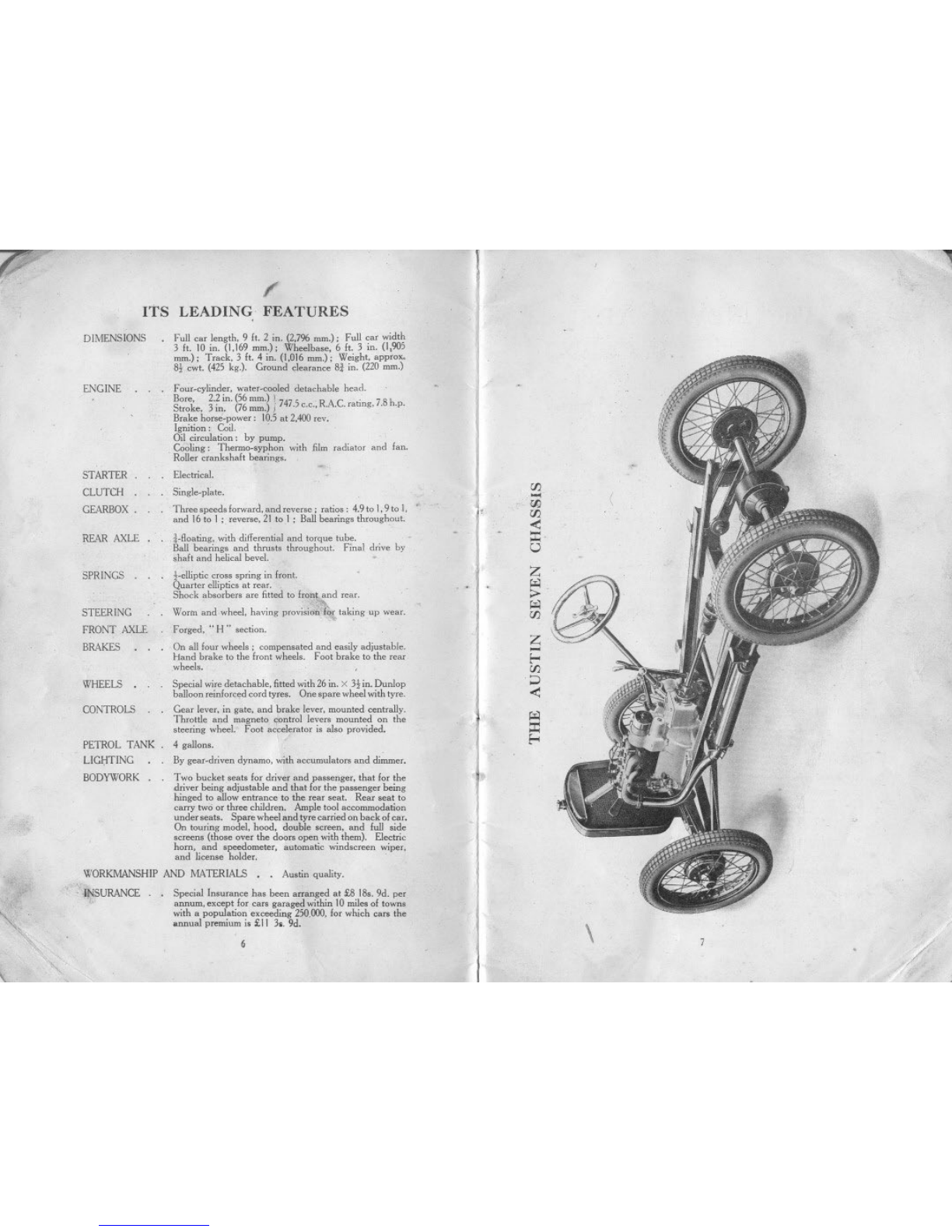
ITS LEADING. FEATURES
DIMENSIONS .Full ca< length, 9 ft. 2 in, (2,7% nun.); Full ca< width
J ft, 10 in. (1,169 mm.); Wheelhaoe, 6 ft, J in, (1,905
nun.); Tcack, J ft, 4 in. (1,016mm.); Weight, appmx.
S, cwt. (425 kg.). Gmund deacance S. in, (220 mm,)
ENGINE Four-cylinder, water-cooled detachable bead.
Bore, 2,2 in. (56 mm.) 1747 5 RAC '7Sh
Stmke, 3 in, (76mm,) j . c.c., . . .catmg,. .p.
Brake ho"e-power; 105 at 2,400 «v,
Ignirion; Coil.
Oil circularion; by pump,
Cooling; Thenno,'yphon with film radiator and fan.
Roller ccanhhaft bearing"
Electrical.
STARTER.
CLUTCH .
GEARBOX.
Single.pl~te.
Th«e 'peed, lorward, and reve"e ; ratio,; 4,9to I,9to 1, .
and 16 to I ; reve"e, 21 to I ; B~ bearing, throughout.
..floaring, with diflerential and torque tube.
Ball bearing, and thru,t, throughout, Final drive by
,haft and helical bevel.
REAR AXLE ,
t-ellipric cro," 'pring in fmnt.
Quarter ellipric, at rea<.
Shock abMber. are fitted to fmn!. and rear.
w; dhelh ' ':~ f'k.
worm an we, avmg pm~,w" M ta mg up wear.
,. ,
Forged, "H" ,ecrion,
, On all four wheel,; compenMted and e.,ily adju,table,
Hand brake to the £ront wheel" Foot brake to the rear
wheel"
Special wiredetacbable, fitted with 26 in. X 3t in, Dunlop
balloon reinforced cord tyre'. One 'pare wheel with tyre.
Gear lever, in gate, and brake lever, mounted centrally.
Throttle and magneto contmI lever. mounted on the
,teering wheel. Foot accelerator i, aI,o pro,"ded,
PETROL TANK, 4 gallon"
LIGI;lTlNG ,By gear-driven dynamo, with accumulato" and dimmer,
BODYWORK , Two bucket ,ea" for driver and p""enger, that for tbe
drive<being adju,table and that for the pa"enger being
hinged to ~ow entrance to the rear ,eat, Rea< ,eat to
CaIT}'two or three children, Ample tool accommodarion
under ,ea", Spare wheel and tyre ca<riedon back ofcar.
On touring model. bood. double 'croen, and full ,ide
,creern (tbo,e over the doo" open witb them). Electric
horn, and 'peedometer, automaric wind,creen wiper,
and licen,e holder,
SPRINGS,
STEERING
FRONT AXLE
BRAKES
WHEELS
CONTROLS
"WORKMANSHIP AND MATERIALS. , Au,rin quality.
. .INSURANCE . , Special In,urance b., been arranged at £8 IS" 9d. per
., annum, except for ca" garaged within 10mile, of town,
witb a popnlarion exceeding 250.000,for which ca<, the
annual premium i, £ 11 J.. 9d,
~~6
"
",
\
/
.
rFJ
...
i1, f/) (
rFJ
<
:I:
u
Z
;>-
rFJ
Z
.....
1-
rFJ
<
:1

f'
The NEW CAR
ON, taking possession of a new car it is advisable to give
It a general exammahon to see that all is complete and
in order. .
Make sure that the tool-kit is complete, check ~ver
according to the list given on page 50. .
If you are not already familiar with Austin cars, we strongly
recommend that this handbook be carefully studied.
Before running see that the car is supplied with fuel and
water and that the engine and gearbox have the necessary
quantities of oil. The battery should contain the required
amount of acid. For quantities of oil and acid see sections
" Lubrication" and" Electrical Equipment."
Should the car be delivered by road it will be ready for
running but if it has been transported by rail or overseas, the
engine may have become stiff through the gumming of the oil
on the pistons. They may be freed by the injection of a little
petrol into the cylinders, through the compression plugs, and then
turning the engine a few revolutions with the starting handle.
When a car is crated for dispatch overseas, water, fuel, and
oil are removed and the battery lelt empty and nncharged.
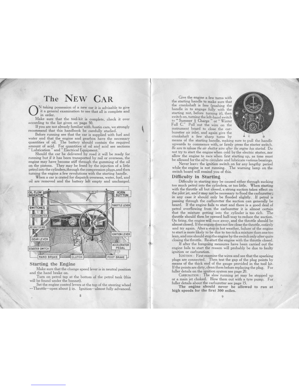
Starting the Engine
Make sure that the change speed lever is in neutral position
and the hand brake on.
Turn on petrol tap at the bottom of the petrol tank (this
will be found under the bonnet).
Set the engine control levers at the top of the steering wheel
-Throttle-open about tiJ1. Ignition-almost fully advanced.
'" 8
'~
,
u,
Give the engine a few turns with
the starting handle to make sure that
the crankshaft is free (pushing the
handle in to engage fully with the
starting nut, before turning it), then
switch on, turning the left-hand switch
to "Summer t Charge" or " Winter
Full c." Pull out the wire on the ,.
instrument board to close the car- I
buretter air inlet, and again give the I, \
crankshaft a few sharp turns by A C B
means of the starting handle, making sure to pull the handle
upwards to commence with, or firmly press the starter switch.
Be suretoreleasetheair shuttErwire after theenginehasstarted. Do
not try to start the engi,\: when cold by the electric starter, nor
allow the engine to race when first starting up, as time must
be allowed for the oil to circulate and lubricate various bearings.
Never lean the ignition switch on,for any lengthy period
while the engine is not running. The warning lamp on the
switch board will remind you of this.
Dift'iculty in Starting
Difficulty in starting may be caused either through sucking
too much petrol into the cylinders, or too little. When starting
with the throttle all but closed, a strong suction takes effect on
the pilot jet, and it may not be necessary to flood the carburetter;
in any case it should only be flooded slightly. If petrol is
passing through the carburetter the suction can generally be
heard. If the engine fails to start and there is a good deal of
petrol overflowing from the carburetter it is almost certain
that the mixture getting into the cylinder is too rich. Tbe
throttle should then be opened half-way to reduce the suction.
On firing, the engine will race away, and the throttle should be
almost closed. Ifthe engine does not fire close the throttle, entirely
and try again. After a stop i;' hot weather, failure of the engine
to start is more likely to be due to too rich a mixture than one too
lean, and one should stop the engine by the switch only after quite
closing the throttle. Re-start the engine with the throttle closed.
If after the foregoing measures have been carried out the
engine fails to start the reason will probably be due to faulty
ignition or carburation.
IGNITION: First examine the wires and see that the sparking
plugs are connected. Then test the gap of the plug points by
means of the thick end of the gauge provided in the tool kit.
If the points are dirty, clean them before replacing the plug. For
fuller details on the ignition system see page 20.
CARBURATION:The slow running jet may be stopped up
or a main jet choked. Blow them out with a tyre pump. For
fuller details about the carburetter see page IS,
The engine should never be allowed to run at
high speeds for the fir~ 300 milt;s.
9
~
(
The NEW CAR
Ot'! taking possessi~n of a new car it is advisable to give
it a general exammatIon to' see that all is complete and
in order, '
Make sure that the tool-kit is complete, check it over
according to the list given on page 50. .
Ifyou are not already familiar with Austin cars, we strongly
recommend that this handbook be carefully studied,
Before running see that the car is supplied with fuel and
wafer and that the engine and gearbox have the necessary
quantities of oil. The battery should contain the required
amount of acid. For quantities of oil and acid see sections
.. Lubrication" and" Electrical Equipment:'
Should the car be delivered by road it will be ready for
running but if it has been transported by rail or overseas, the
engine may have become stiff through the gumming of the oil
on the pistons. They may be freed by the injection of a little
petrol into the cylinders,through the compression plllgs,and then
turning the engine a few revolutions with the starting handle.
When a car is crated for dispatch overseas. water, fuel, and
oil are removed and the battery left empty and uncharged.
Starting the Engine
Make sure that the change speed lever is in neutral position
and the hand brake on,
Turn on petrol tap at the bottom of the petrol tank (this
will be found under the bonnet),
Set the engine control levers at the top of the steering wheel
-Throttle-open about tiJ1' Ignition-almost fully advanced.
'" 8
.'"
\,
,
Give the engine a few turns with
the starting handle to make sure that
the crankshaft is free (pushing the
handle in to engage fully with the
starting nut, before turning it), then
switch on, turnin" the left-hand switch
to .. Summer iCharge" or .. Winter
Full C:' Pull 'out the wire on the
instrument board to close the car-
buretter air inlet, and again give the II\
crankshaft a few sharp turns by A C B
means of the starting handle, making sure to pull the handle
upwards to commence with, or firmly press the starter switch,
Be sure to releasethe air shutter wire after the engine has started. Do
not try to start the engi~e when cold by the electric starter, nor
allow the engine to race when first starting up, as time must
be allowed for the oil to circulate and lubricate various bearings,
Never leave the ignition switch on for any lengthy period
while the engine is not running. The warning lamp on the
switch board will remind you of this.
Difficulty in Starting,
Difficulty in starting may be caused either through sucking
too much petrol into the cylinders, or too little. When starting
with the throttle all but closed, a strong suction takes effect on
the pilot jet, and it may not be necessary to flood the carburetter;
in any case it should only be flooded slightly. If petrol is
passing through the carburetter the suction can generally be
heard. If the engine fails to start and there is a good deal of
petrol overflowing from the carburetter it is almost certain
that the mixture getting into the cylinder is too rich, The
throttle should then be opened half-way to reduce the suction.
On firing, the engine will race away, and the throttle should be
alinost closed. If the engine does not fire close the throttle, entirely
and try again. After a stop i;' hot weather, failure of the engine
to start is more likely to be due to too rich a mixture than one too
lean, and one should stop the engine by the switch only after quite
closing the throttle. Re-start the engine with the throttle closed.
If after the foregoing measures have been carried out the
engine fails to start the reason will probably be due to faulty
ignition or carburation.
iGNITION: First examine the wires and see that the sparking
plugs are connected, Then test the gap of the plug points by
means of the thick end of the gauge provided in the tool kit.
If the points are dirty, clean them before replacing the plug. For
fuller details on the ignition system see page 20,
CARBURATION:The slow running jet may be stopped up
or a main jet choked. Blow them out with a tyre pump: For
fuller details about the carburetter see page 15.
The engine should never be allowed to run at
high speeds for the first 300 miles.
9
,
.'
'\
t"
CONTROL OF THE CAR
Setting of Control Levers
j\FTER having started the engine, keep the ig
,
nition lever in
the advanced pos[tion; should the engine commence to
," rumble" or run roughly, retard the lever, but advance I
it,again as soon as the load on the engine is lessened. The
" gas" lever should be set generally for slow running and the
speed of the car controlled by the accelerator pedal.
Changing Gear
Double declutching will be found the best method of gear
changing on the Austin Seven,,- and should be adopted
straight away. Also when changing up the foot should' be
taken off the accelerator pedal, and when changing to a
lower gear it should be held down. The car shOllld be well
accelerated on each speed when changing up, and a
deliberate pause should be made with the gear lever in neutral
position and with the clutch in whether changing up or down.
The catch below the knob of the gear lever must be raised to
allow the reverse gear to be engaged.
Always change gear early on a hill; never allow the engine
to labour in any gear and expect it to pick up speed on changing
into a lower one when the car
has nearly stopped.
Keep the foot off the clutch
pedal except in heavy traffic.
Even then, do not allow the
weight of the foot to be taken
by the pedal. The slipping
of the clutch caused by this
practice heats and wears it
badly.
When descending a long
hill, supplement the action of
the foot-brake at intervals by
the use of the hand-brake for
brief periods. It is often
advisable to engage one of the lower gears before commencing
a steep descent, with throttle closed. When using the brake,
keep the clutch in, disengaging it at the last moment if stopping
the car.
The driving seat of the Austin Seven is adjustable for
position and this convenience should be taken advantage of so
as to obtain the greatest comfort, '
'" 10
.""""
,I
~
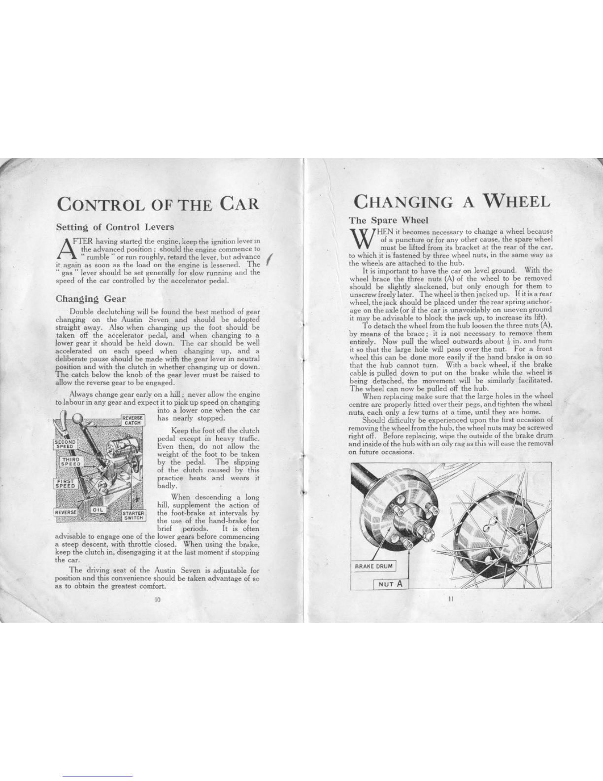
CHANGING A WHEEL
The Spare Wheel
WHEN it becomes necessary to change a wheel because
.of a puncture or for any other cause, the spare wheel
must be lifted from its bracket at the rear of the car,
to which it is fastened by three wheel nuts, in the same way as
the wheels are attached to the hub.
It is important to have the car on level ground. With the
wheel brace the three nuts (A) of the wheel to be removed
should be slightly slackened, but only enough for them to
unscrew freely later. The wheel is then jacked up. If it is a rear
wheel, the jack should be placed under the rear spring anchor-
age on the axle (or if the car is unavoidably on uneven ground
it may be advisable to block the jack up, to increase its lift).
To detach the wheel from the hub loosen the three nuts (A),
by means of the brace; it is not necessary to remove them
entirely. Now pull the wheel outwards about! in. and turn
it so that the large hole will pass over the nut. For a front
wheel this can be done more easily if the hand brake is on so
that the hub cannot turn. With a back wheel, if the brake
cable is pulled down to put on the brake while the wheel is
being detached, the movement will be similarly facilitated.
The wheel can now be pulled off the hub.
When replacing make sure that the large holes in the wheel
centre are properly fitted over their pegs, and tighten the wheel
nuts, each only a few turns at a time, until they are home.
Should diiticulty be experienced upon the first occasion of
removing the wheel from the hub, the wheel nuts may be screwed
right off. Before replacing, wipe the outside of the brake drum
and inside of the hub with an oily rag as this will ease the removal
on future occasions.
NUT A
11
.(
(".
PERIODICAL
ATTENTIONS
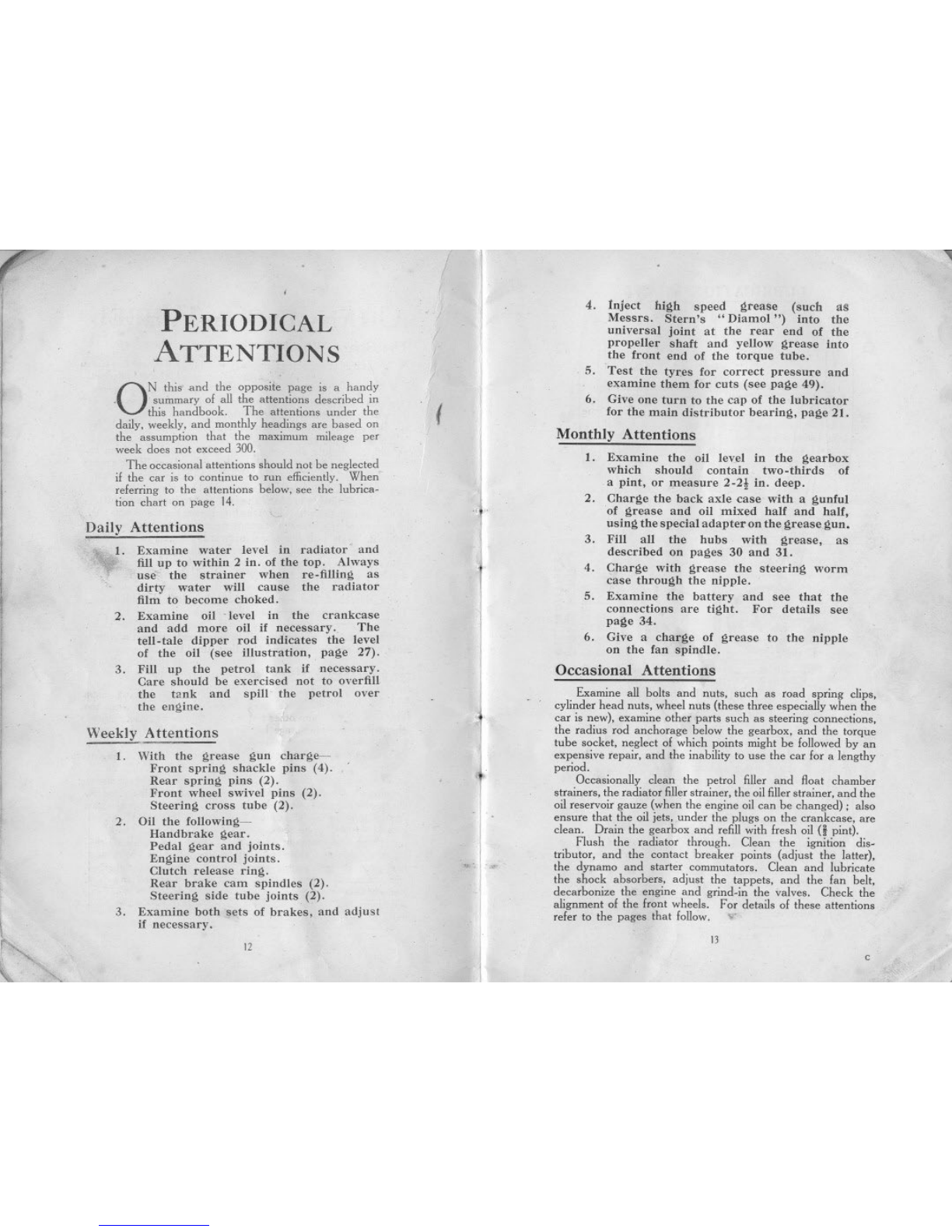
ONthis and the opposiie page is a handy
..summary 01 all the attentions described in
this handbook. The attentions under the
daily. weekly. and monthly headings are based on
the assumption that the maximum mileage per
week does not exceed 300.
The occasional attentions should not be neglected
il the car is to continue to run efficiently. When
relerring to the attentions below. see the lubrica-
tion chart on page 14. "
Daily Attentions
1. Examine water level in radiator' and
fill up to within 2 in. of the top. Always
use'" the strainer when re-filling as
dirty water will cause the radiator
film to become choked.
2. Examine oil 'level in the crankcase
and add more oil if necessary. The
tell-tale dipper rod indicates the level
of the oil (see illustration, page 27).
3. Fill up the petrol tank if necessary.
Care should be exercised not to overfill
the tank and spill the petrol over
the engine.
Weekly Attentions ..
1. With the grease gun charge-
Front spring shackle pins (4).
Rear spring pins (2).
Front wheel swivel pins (2).
Steering cross tube (2).
2. Oil the following-
Handbrake gear.
Pedal gear and joints.
Engine control joints.
Clutch release ring.
Rear brake cam spindles (2).
Steering side tube joints (2).
3. Examine both sets of brakes, and adjust
if necessary.
r-" 12
'- "
,
(
4. Inject high speed grease (such as
Messrs. Stern's" Diamol") into the
universal joint at the rear end of the
propeller shaft and yellow grease into
the front eud of the torque tube.
5. Test the tyres for correct pressure and
examine them for cuts (see page 49).
6. Give one turn to the cap of the lubricator
for the main distributor bearing, page 21.
Monthly Attentions
1. Examine the oil level in the gearbox
which should contain two-thirds of
a pint, or measure 2-21 iu. deep.
2. Charge the back axle case with a gunful
of grease and oil mixed half and half,
using the special adapter on the grease gun.
3. Fill all the hubs with grease, as
described on pages 30 and 31.
4. Charge with grease the steering worm
case through the nipple.
5. Examine the battery and see that the
connections are tight. For details see
page 34.
6. Give a charge of grease to the nipple
on the fan spindle.
Occasional Attentions
",
Examine all bolts and nuts. such as road spring clips,
cylinder head nuts. wheel nuts (these three especially when the
car is new). examine other parts such as steering connections.
the radius rod anchorage below the gearbox. and the torque
tube socket. neglect 01 which points might be lollowed by an
expensive repair. and the inability to use the car lor a lengthy
period.
Occasionally clean the petrol filler and float chamber
strainers. the radiator filler strainer. the oil filler strainer. and the
oil reservoir gauze (when the engine oil can be changed); also
ensure that the oil jets. .under the plugs on the crankcase. are
clean. Drain the gearbox and refill with fresh oil (i pint).
Flush the radiator through. Clean the ignition dis-
tributor, and the contact breaker points (adjust the latter),
the dynamo and starter commutators. Clean and lubricate
the shock absorbers. adjust the tappets. and the fan belt,
decarbonize the engine and grind-in the valves. Check the
alignment of the front wheels. For details of these attentions
reler to the pages that follow. IT
1
13
c
r
I- ,
I,
Il
t'", '"
",
,
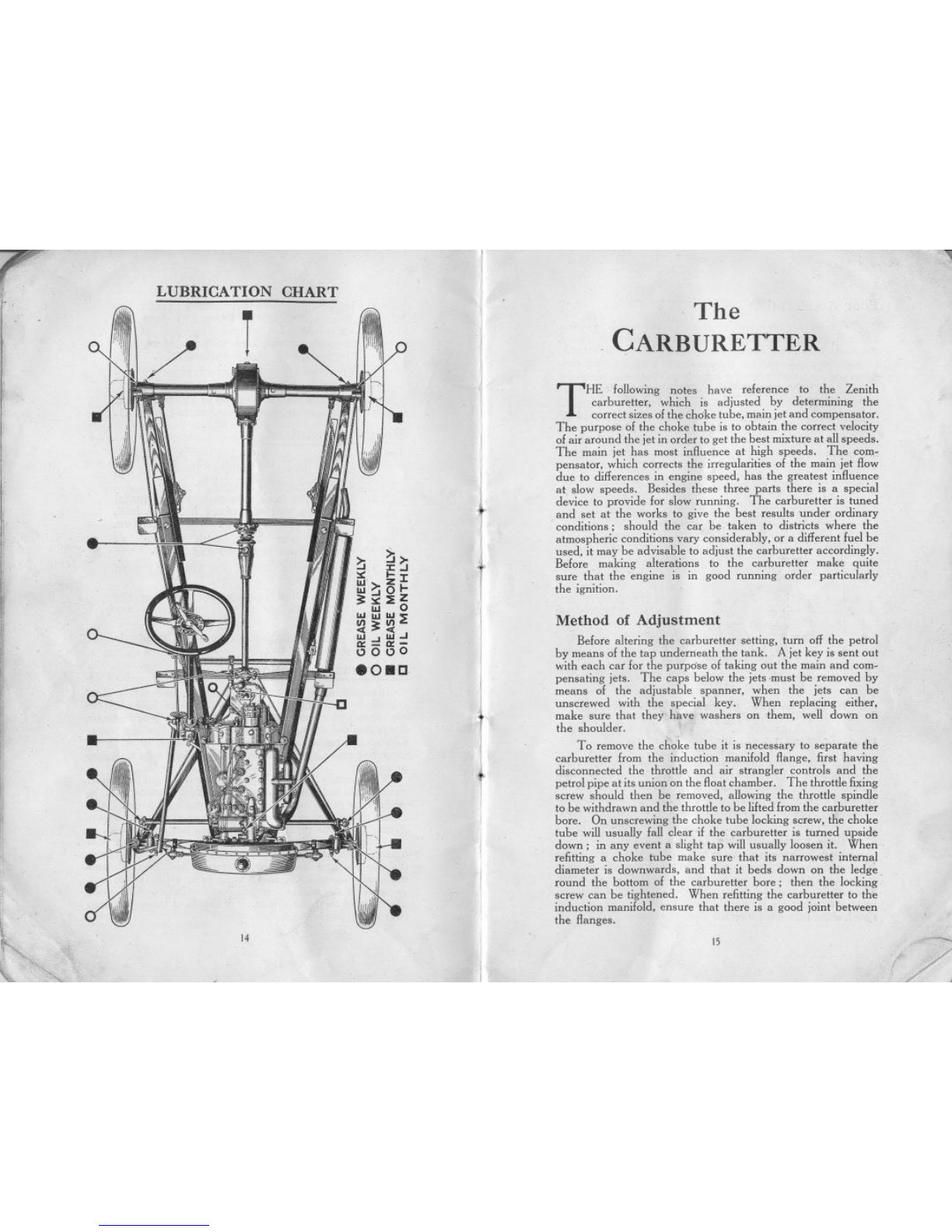
LUBRICATION CHART The
CARBURETTER
THE following notes have reference to the Zenith
carhuretter, which is adjusted by determining the
correct sizes of the choke tube, main jet and compensator,
The purpose of the choke tube is to obtain the correct velocity
of air around the jet in order to get the best mixture at all speeds.
The main jet has most influence at high speeds, The com-
pensator, which corrects the irregularities of the main jet flow
due to differences in engine speed, has the greatest influence
at slow speeds. Besides these three parts there is a special
device to provide for slow running. The carburetter is tuned
and set at the works to give the best results under ordinary
conditions; should the car be taken to districts where the
atmospheric conditions vary considerably, or a different fuel be
used, it may be advisable to adjust the carburetter accordingly.
Before making alterations to the carburetter make quite
sure that the engine is in good running order particularly
the ignition.
~ ~:J
~...1:
III Z
1II~01-
~~::EZ
III 0
IIIIIIIII~
111>111'"
«:>«
111 111""
0:-0:-
0000
eO8C
Method of Adjustment
Before altering the carburetter setting, turn off the petrol
by means of the tap underneath the tank. A jet key is sent out
with each car for the purpose of taking out the main and com-
pensating jets. The caps below the jets .must be removed by
means of the adjustable spanner, when the jets can be
unscrewed with the special key. When replacing either,
make sure that they have washers on them, well down on
the shoulder.
1
I
I
To remove the choke tube it is necessary to separate the
carburetter from the induction manifold flange, first having
disconnected the throttle and air strangler controls and the
petrol pipe at its union on the float chamber, The throttle fixing
screw should then be removed, allowing the throttle spindle
to be withdrawn and the throttle to be lifted from the carburetter
bore. On unscrewing the choke tube locking screw, the choke
tube will usually fall clear if the carburetter is turned upside
down; in any event a slight tap will usually loosen it. When
refitting a choke tube make sure that its narrowest internal
diameter is downwards, and that it beds down on the ledge.
round the bottom of the carburetter bore; then the locking
screw can be tightened. When refitting the carburetter to the
induction manifold, ensure that there is a good joint between
the flanges.
14
.~ /
15 --

7~
Poor Acceleration
When picking up is bad, or when it is impossible to obtain
"a sharp acceleration no matter what size of compensator is used,
the choke tube is too large. The tests for" pick-up" should
be made on the level. Let the car run at a good speed, slow
down slightly; then press the accelerator down sharply as far
as it will go. .The car should then quickly pick up its previous
speed without hesitation.
If, instead of accelerating, the engine stops, try larger
- compensators.If, in spite of this, the picking up is not good,
the choke tube is too large, in which case fit another, one or two
millimetres smaller, and try again until the acceleration is perfect.
No Power
CHOKE
TUBE
LOCKNUT !
When the car gets away badly, and popping-back occurs
in the carburetter when accelerating, the main jet is too small.
This popping-back occurs at irregular intervals, and the engine
has little power and cannot drive the car at a high speed. Fit
larger jets until these explosions in the inlet pipe disappear and
then test until the right jet has been found, as indicated in
previous paragraph.
The popping-back may also be due to air leaking into the
induction pipe through joints which are not air-tight, to leakage
at the extra air valve, or to the valves not closing properly. Test
the tappet clearances by the thin blade of the sparking plug
and tappet clearance gauge. In some cases popping back is
due to the engine being cold, and will cease when it has been
running for a little time.
:j
I
j
~
~I
THROTTLE
VALV'
AIR HOLE Irregular Firing
The trials of different compensators should take place
up an incline, with the engine driving the car at a'speed it can
scarcely maintain, say 300 to 500 r.p.m. The compensator is
too large when the engine at this speed runs with an irregular,
jerky motion; the hunting which takes place at high speed in
the case of too large a main jet is found at Iow speeds with too
large a compensator. The size of the compensator is decreased
until all the cylinders fire evenly and the exhaust is quite regular.
As in the case of the main jet, if two compensators give equal
results, choose the smaller on the score of economy. The
compensator plays a great part in the picking-up, but when the
size of the former is determined according to the above method,
it is generally suitable for an excellentacceleration.
[A" iNLET 1
MAINJET
COMPENSATING JET
CAPS
Tb. Z..tth ,arhn""", typ' 22FZ. Th. ,tandard s."'ng Is,
,hnk. tuh. 15, main j.t 70, oomp ting j.t 75, ,lnw ~nnlng
tnb. 26.35.
Lack of Speed
Withtoo small a choke tube the pick-up is excellent but
the speed attained on the level with the accelerator right down
is insutlicient-a larger choke tube is then fitted, and the jet
altered proportionally, when the tests are continued until a
satisfactory maximum speed is attained.
Choking and" Hunting"
To ascertain the correct size of the main jet, the test is also
made on the level at high speed. A jet which is much too large
causes choking, and the engine often runs jerkily and hunts. .
The petrol consumption is also excessive. The jet that gives the
greatest speed on the level is chosen. If two jets give an equal
speed, choose the smaller on the score of economy.
Slow Running Device
Note that too much petrol for slow running causes choking
and hesitation in pick-up. A want of petrol, on the other hand,
causes a loss of power and misfiring at the same time. It is
therefore necessary to regulate the slow running as carefully as
possible. By first releasing the lock nut and then turning the
knurled screw B to the right a greater flow of petrol is obtained,
while it can be cut down by turning the screw to the left.
This device <an be drawn out after releasing the lock-nut
and slackening the round-headed screw A on the side. It is
possible to unscrew the lower hall C. from the upper with a pair
of pliers, in order to see if it is clear. .
t6
[
"
17
.,

r~
)
I
II
~I
III
"
li,.,[
,."
I
111
I
ili
~I
1
:1
.
d
,
There are other factors quite apart from the carburetter
which have great influence on slow running (slow running when
-the engine is out of gear and the car is stationary),
These factors are:-
Joints .not air-tight. Valve guides worn. Valves not
seating. Ignition too much advanced.
Engine Misfires and Stops
In tests made as in the last instance. the engine misses fire
now and again, the transmission receives jerks, and the engine
finally stops. In this case fit a larger compensator until the
engine runs regularly.
The Float Chamber
,Petrol leakage from the float chamber may be due to the caps
under the jets not being tight, or a leaking petrol pipe union.
If no leakage seems possible at these points, suspect float
chamber derangement, which is causing petrol to overflow the
jets. It may be that the float control is out of adjustment, the
float may be perforated, or the needle not seating properly
owing to dirt on the needle seating. The remedy for the last
mentioned defect is obvious; the first two defects should be
left to an expert to remedy. When replacing the float chamber
cover, ensure that the needle ha~ entered its seating, and is free
to be moved by the float: also that the cover beds down
properly, then secure it with the clip;
Petrol Flow
If the petrol supply from the tank is unrestricted yet
difficult starting points to insufficient petrol, there is a restriction
somewhere in the carburetter. First, see that the air vent in the
float chamber cover, under the retaining clip, is clear. Should
it be so, the next point to examine is the filter below the float
chamber, and the passage from it to the needle seating. Access
to this filter is given by removing the petrol pipe union and un-
screwing the petrol inlet nut, on the bottom of the float chamber.
The slow running tube and jet may be stopped up. Remove
the slow running tube bodily, having loosened its locking screw.
In the bottom of the tube is a small filter which can be prised out
and cleaned. The bottom portion of the tube, comprising the
jet, may be then unscrewed from the top portion, and the jet
cleaned if stopped up; two flats on the jet allow a small spanner
to be used to unscrew it. Lastly the compensating or main
jets may be choked. Remove them and clear them. Never
insert anything in any of the jets; always blow through to clear
them; a tyre pump can be used if desired. When refitting the
slow running tube ensure that it beds down to its collar at the
top, with the small projection under the collar fitting the groove
.in the carburetter casting; then tighten the locking screw,
16
\
t
.
1
.1
f..
I
I
I
I
"""IIi
Difficulty in Starting
This may be due to several causes-
Float chamber air vent stopped up (see previous page).
Slow running tube stopped up (see previous page),
Plug points too far apart, See" Ignition System,"
Ignition lever badly placed. See next paragraph.
Jets choked up (see previous page).
With variable ignition there is generally a particularly
favourable setting for easy starting. One who is continually
using a car soon recognises this position.
STANDARD REPAIR
CHARGES ~
THE following adjustments and repairs described in this
handbook are included in the Austin Seven Schedule
of Charges for Repairs, which quotes over ninety prices
for repairs to the Austin Seven, Owners will find it to their
advantage to have their car adjustments and repairs effected
by Austin agents at these standard prices,
Greasing spring shackles, steering and brake, and other
small connections,
Ditto, but including rear axle, universal joint, steering box
and front hubs.
Taking down, cleaning and greasing all road springs,
reassembling with new bolts and bushes where required.
Dismantling shock absorbers, then cleaning and adjusting
and refixing,
Adjusting and compensating brakes.
Relining brakes, front or rear.
Removing cylinder head; decarbonising and grinding in
valves: adjusting tappets and tuning-up engine on the
road.
Fitting new cylinder head and/or gasket.
Adjusting valve tappets, cleaning and adjusting contact
breaker, distributor and sparking plugs; cleaning out
carburetter jets,
Fitting new valves,
Removing base chamber, cleaning oil filter, examining
interior of engine, and refilling with new oil.
Removing dynamo from car; cleaning and adjusting,
examining battery and connections, and refilling battery
with acid as required.
Tracking up front wheels by adjusting length of cross
steering tube,
Adjusting mesh of steering worm and wheel.
19
J
I
I
T
!/
~j
i
l
l!!
lil
l
I!ii
I
1]1
l:1
\, """
The IGNITION SYSTEM
THE recommendations that follow apply to the C.A.V.-
Lucas ignition equipment.
The set should be examined occasionally and the
following attentions given. only if they seem necessary.
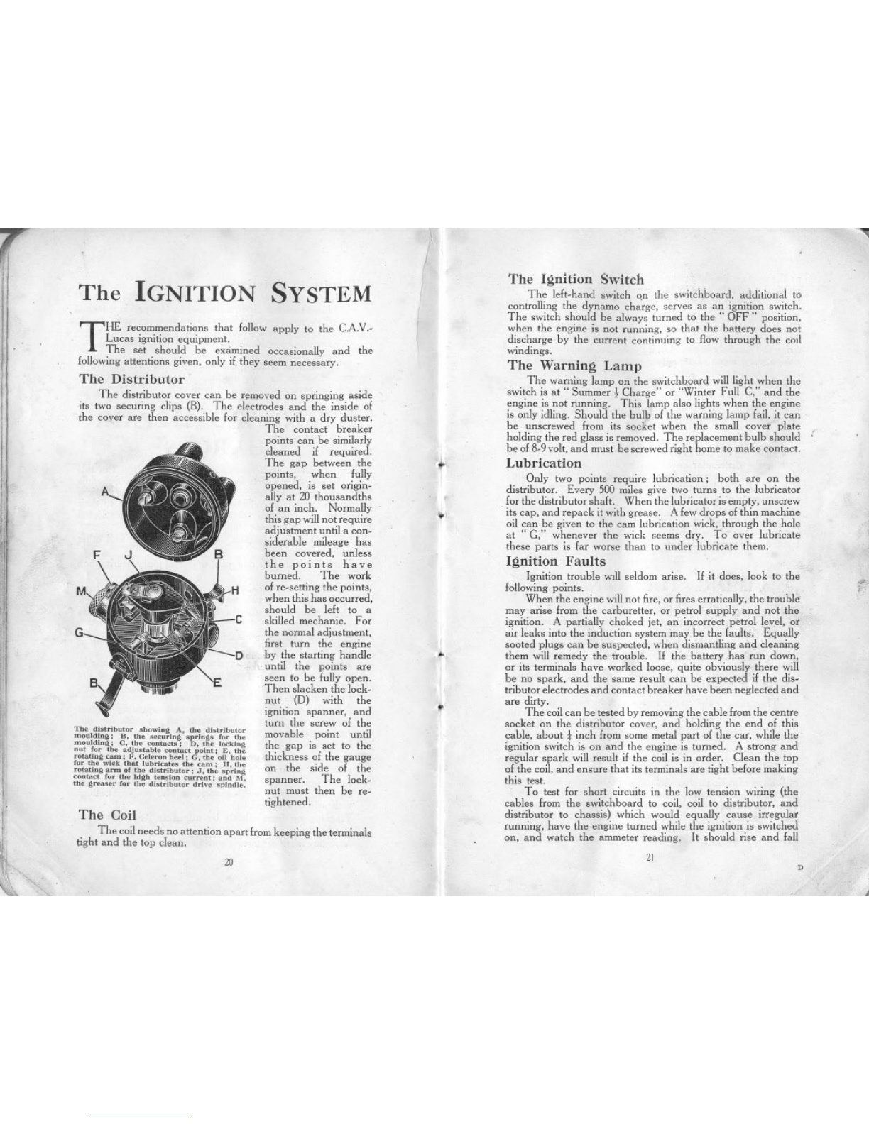
The Distributor
The distributor cover can be r~moved on springing aside'
its two securing clips (B). The electrodes and the inside of
the cover are then accessible for cleaning with a dry duster.
The contact breaker
points can be similarly
cleaned if required.
The gap between the
points, when fully
opened, is set origin-
ally at 20 thousandths
of an inch. Normally
this gap will not require
adjustment until a con-
siderable mileage has
been covered, unless
the points have
burned. The work
.ofre-setting the points,
when this has occurred.
should be left to a
skilled mechanic. For
the normal adjustment,
first turn the engine
by the starting handle
until the points are
seen to be fully open.
Then slacken the lock-
nt,lt (D) with the
ignition spanner, and
turn the screw of the
movable point until
the gap is set to the
thickness of the gauge
on the side of the
spanner. The lock-
nut must then be re-
tightened.
A
F
G
The dl"ributor 'bowiug A, the di"ributor
moulding; B, the ,&uring ..ring, for the
moulding; C, the contac"; D, tbe [ocking
nnt for tbe adjn"abl. contact point; E. the
rotating cam; F, Celeron beel; G, the 011bole
for the wick tbat lubricat.. the cam; H, the
rotating arm of the dl"rlbutor; J, the ,pring
conta" for tbe blgh ten,ion current; and M,
the gream fnr tb. dl'tributor drive ,pindle.
The Coil
The coilneeds no attention apart fromkeeping the terminal.
tight and the top clean.
20
I
I
I
\
.~
."
I
!I..
t
""Ill
The Ignition Switch .
The left-hand switch on the switchboard, additional to
controlling the dynamo cha'rge, serves as an ignition switch.
The switch should be always turned to the" OFF" position,
when the engine is not running, so that the battery does not
discharge by the current continuing to /low through the coil
windings.
The Warning Lamp
The warning lamp on the switchboard will light when the
switch is at " Summer:\- Charge" or "Winter Full C," and the
engine is not running. This lamp also lights when the engine
is only idling. Should the bulb of the warning lamp fail, it can
be unscrewed from its socket when the small cover plate
holding the red glass is removed. The replacement bulb should
be of 8-9 volt, and must be screwed right home to make contact.
Lubrication
Only two points require lubfication; both are on the
distributor. Every 500 miles give two turns to the lubricator
for the distributor shaft. When the lubricator is empty, unscrew
.its cap. and repack it with grease. Afew drops of thin machine
oil can be given to the cam lubrication wick, through the hole
at "C," whenever the wick seems dry. To over lubricate
these parts is far worse than to under lubricate them.
Ignition Faults
Ignition trouble will seldom arise. If it does, look to the
following points.
When the engine will not fire, or fires erratically, the trouble
may arise from the carburetter. or petrol supply and.notthe
ignition. A partially choked jet, an incorrect petrol level, or
air leaks into the induction system may be the faults. Equally
sooted plugs can be suspected, when dismantling and cleaning
them will romedy the trouble. If the battery has run down,
or its terminals have worked loose, quite obviously there will
be no spark, and the same result can be expected if the dis-
tributor electrodes and contact breaker have been neglected and
are dirty. .
The coil can be tested by removing the cable from the centre
socket on the distributor cover, and holcling the end of this
cable, about! inch from some metal part of the car, while the
ignition switch is on and the engine is turned. A strong and
regular spark will result if the coil is in order. Clean the top
of the coil, and ensure that its terminals are tight before making
this test.
To test for short circuits in the Iow tension wiring (the
cables from the switchboard to coil, coil to distributor, and
distributor to cbassis) which would equally cause irregular
running, have the engine turned while the ignition is switched
on, and watch the ammeter reading. It should rise and fall
:
""
:;".
21 D
,
!
!llr
ij
If'
!,
I
":<1
~t.
~\,
as the contact hreaker points close and open. This test will
also indicate if the contact hreaker is functioning correctly. If
the contacts remain open, or do notfully close, the reading will
not fluctuate.
)f the high tension cahles from the distributor to the plugs,
are not pushed home into their sockets in the distributor, mis-
firing will similarly occur. Or, if the rubber insulation on these
cables show signs of perishing and cracking, there may be
leakage of the current, giving rise to the same symptoms. Re-
newing the cables is then the remedy.
If after verifying these points, the trouble remains undis-
covered, the equipment should be examined and tested by the
nearest service depot of the makers.
When Leaving the Car
When the -car has to be parked or left in the street for any
period, the distributor cover can be lifted, and the rotating
distributor arm removed from its mounting above the cam;
it just pulls off without turning. The car is then secure against
any attempts at theft, and the distributor arm can be carried
in the pocket until the car is to be used. again. When refittil)g
it, note that the projection up inside its moulding, fits the slot
cut in the top of the spindle on which it mounts, so that it is
located for correct timing.
~
II
'f
,
TIMING IGNITION ,
THE
In timing the ignition (which is only necessary if the dis-
tributor, with or without the dynamo, has been removed from
the car) the first operation is to rem6ve all the sparking plugs,
except the front-No. I-and turn the crankshaft by the starting
handle until compression is felt. This means that'No. I cylinder
will be the next one to fire. , '.;..0
Flywheel Timing Marks
Then remove the starter motor with its casing (inside the
car) by unscrewing the securing studs, one on each side of the
casing, and lifting the assembly clear vertically off the locating
dowel on the crankcase. A line will be seen on the back of the
flywheel. marked 1 and 4 (see illustration on page 28). This
line is parallel to the throws of the crankshaft, and when this
line is vertical it naturally follows that Nos. I and 4 pistons are
at the top of their stroke. In this case, howe.;er,..weare only
dealing with No. I. Now turn the flywheel uniiL,this line is
1t in. to 2 in. before the top centre. (We cannot quote a
definite figure as this depends on the characteristics of the
particular engine). This is the position at which the spark
should take place at the sparking plug, when the ignition
I
'~
.'
.1
"22
~
I
'L
,I" ,i!i;!;r,y&
"
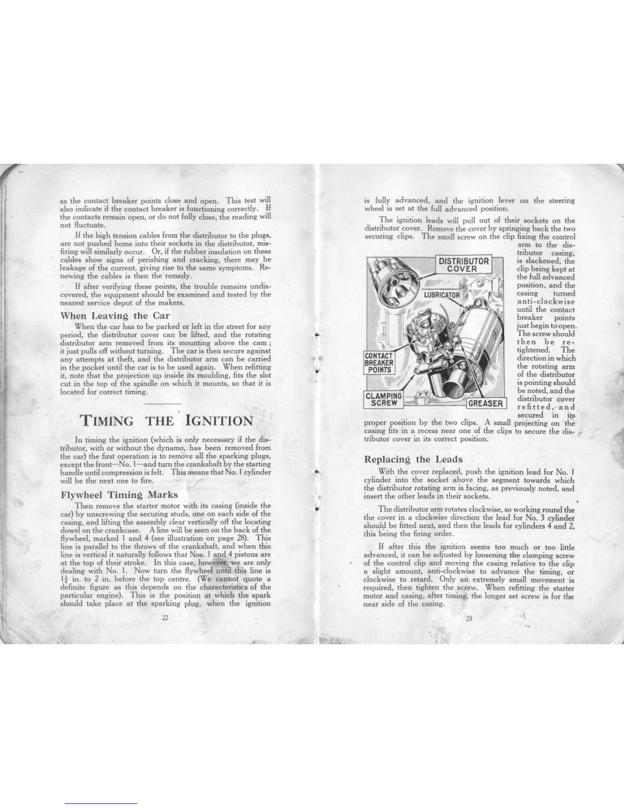
is fully advanced, and the ignition lever on the steering
wheel is set at the full advanced position.
The ignition leads will pull out of their sockets on the
distributor cover. Remove the cover by springing back the two
securing clips. The small screw on the clip fixing the control
arm to the dis-
,tributor casing,
is slackened, the
clip being kept at
the full advanced
position, and the
casing turned
anti-clockwise
until the contact
breaker points
just begin to open.
The screw should
then be re-
tightened. The
direction in which
the rotating arm
of the distributor
is pointing should
be noted, and the
distributor cover
refitted,.. and,
secured in iI!"
proper position by the two clips. A small projecting on the
casing fits in a recess near one of the clips to secure the disc ;'
tributor cover in its correct position.
?+
~.
~1iiI
Replacing the Leads
With the cover replaced, push the ignition lead for No. 1
cylinder into the socket above the segment towards which
the distributor rotating arm is facing, as previously noted, and
insert the other leads in their sockets.
The distributor arm rotates clockwise, so working round the
the cover in a clockwise direction the lead for No. 3 cylinder
shoul,! be fitted next, and then the leads for cylinders 4 and 2,
this being the firing order.
If after this the ignition seems too much or too little
advanced, it can be adjusted by loosening the clamping screw
of the control clip and moving the casing relative to the clip
a slight amount, anti-clockwise to advance the timing, or
clockwise to retard. Only an extremely small movement 'is
required, then tighten the .screw. When refitting the starter
motor and casing, after timing, the longer set screw is for the
near side of the casing.
. , 23
.~
."",~
..~~
"
"
"'Ill
The
COOLING SYSTEM
The entire circulating system should be tboroughly flushed
out occasionally. To do this open the drain tap at the bottom,
place a hose in the filler, and run fresh water through.
Trouble arising from a damaged radiator generally
necessitates its dismantling and despatch to a repair depot.
THE cooling of the e
.
ngine is maintained by a capacious
radiator which should be filled, with rain water, if
.available, up to within 2 in. of the top of the filler. The
capacity of the radiator, pipes and cylinder jackets is
9-10 pints.
How To USE THE
GREASE GUN
'ill
ill
,
..1 '.
iili
1Ii
l
./
.'.
.
':,"
~I
~
::1
In Cold Weather
Care should be taken to see that the water is drained off
completely, f~r, in case of freezing, it will do harm by lodging in
small spaces and fracture of the cylinder block may result, In
Great Britain, the climate does not very often call for the cooling
system to be drained, but it is well to err on the right side and
take. due precaution against damage if frost be threatened,
Glycerine mixed with the water will reduce its freezing point
by several degrees, If added it should be in the proportion of
15% to 20%, In cold weather use the Austin radiator muff.
To prevent the gradual formation of deposits in the cooling
system, with consequent impeding of the circulation, the use of
hard water should be avoided. Rain-water, syphoned from the
top of the barrel where it is clean, should be used, or, failing
that, water that has been boiled.
1'¥
Screw the handle right out. Unscrew the extension piece
by the knurled nut at the base of the barrel and fill the barrel
with grease; then replace. Give the handle one complete
turn: this fills the telescopic extension piece at the end of the
gun which will project. Now place the end of the gun on the
nipple attached to that part of the car which it is desired to
grease, and push. The extension piece closes and discharges
the grease into the nipple.
Give the handle another turn and the gun is once more
chargee.!. Continue until the barrel is empty and then refill.
For the back axle a special adapter is used on the gun in
place of the standard telescopic end. This adapter screws
ihto the axle, in place of the plug. When replacing the plug,
do not omit its washer. It is important not to let dirt get into
the adapter which; when not in use, is screwed on to the
side of the gun.
,
'f'
,
I;:
.,
"
Causes of Overheating
Overheating may be attributed to one or more of the
following:
Slack fan belt. The belt can be tightened by turning the
fan spindle in its bracket after loosening the clamping-nut.
Excessive carbon deposit in cylinders. See" Running
Adjustments."
.Running with ignition too far retarded.
Using oil of poor quality, or lack of oil in the reservoir.
See" Engine Lubrication." .
Partial choking of the oil jets. See" Engine Lubrication."
Improper carburetter adjustment, giving 'a mixture too rich
or too weak. See" The Carburetter."
Failure of water to circulate, because of choked radiator
tubes, water level below the tops of the radiator tubes, or loss
of water through leakage from connections.
Overcooling is almost as bad as overheating. If the engine
tends to be too cool, use a radiator muff, or possibly, in winter,
the fan belt can be removed without the engine running too hot.
DON'T!
'"
~!1
Don't, pleasedon't-
Don't leave the car in gear with the handbrake off.
Don't make a fast run. with the radiator muff down.
Don't fill the radiator with cold water whe'; the engine is hot.
Don't try to turn the engine without first pushing the starting-
. handle in to engage fully with the starting nut.
Don't be ,cruel to the starter if the engine will not fire.
Don't touch th" reverse catch when changing gear.
Don't put an excessive quantity of lubricant in the gear box.
Don't pour oil into the engine with the strainer removed.
Don't forget the ignition switch when starting up.
Don't leave the ignition switched on when the engine is
not running. .
Don't coast with the engine running and the clutch held out.
Don't run the engine in a closed garage. (The exhaust gases
are highly toxic and a very small amount in a restricted
atmosphere will produce grave, if not fatal, results.)
25
.,,
..
24
"."" ~

'<
l'
"
LUBRICA TION
Choi~e of Lubricants
FOR the engine or gear box use one of the following oils:-
Stern's" Sternol W.W." Heavy; "Mobiloil BB."; Price's
"Motorine C:'; Speedwell" Sans Egal Zero "; "Triple
Shell" ; "Speedolene B. Heavy"; Texaco "Heavy";
Filtrate" Extra Heavy"; "Royal Snowdrift 3 "; Wakefield's
"Castrol XL"; Duckham's" Adcol N P 3-4"; and
" Veedol" Heavy No. 4.
Use ordinary" engine" oil in a small can, and ordinary
yellow grease for greasing.
Both these lubricants can be obtained from any garage or
repair shop.
Use Stern's" Diamol" or Price's High Melting Point
Grease {or the rear universal joint of the drive shaft.
The Engine
For the engine, where the recommended oils are not
obtainable, oil of approximately the same constituents and
viscosity should be used. If the oil is too thick it will
tend to clog and carbonise, and if too thin it might lead to "
scoring of the pistons and bearings. Assurance that oil is
continuously circulating is given to the driver by means of
the tell.tale button on the instrument board, which protrudes
when the oil is circulating.
It is essential that all receptacles for oil be kept perfectly
clean. Dirty oil
leads to undue
wear of allbearings,
or might even clog
up the oiling
system and prevent
it ,,:orking, thus
causmg an engme
seizure and much
trouble and ex.
pense. The oil
filler strainer (A)
is detachable for
cleaning, After the
first 500.800 miles
running, drain the
original oil from
j,
I,IU
ti
,:
1i
\~
"'j
11:
1
1
"
"
',
H
"
",
"il'
P.
II~
I1
iJI
,,:"
IH
'I
It
,.
1
"
,
'
,
~"
'
,
,i
I
I'
III
I"I'
'Ii,
"1
1
""
\:
~
"
'I
~\
I
f
',.
f
,
",
I!
J
26
It
I
.,
PUMP
the reservoir by'removing the plug in the bottom, while the
engine is hot, Drain the reservoir completely, Never pour
oil into the engine except through the strainer. "
After the first re.filling it is advisable to change the oil in the
engine entirely after every I,200 to I,500miles running or sooner.
Every 2,400-3,000 rlliles remove the oil reservoir. The"
gauze oil tray will then be accessible for removal. Carefully
clean the gauze and remove all dirt from inside the reservoir
and replace them. Carefully remake the joint with the packing
washer, covering both sides of it with grease. When tightening
up the nuts holding the oil reservoir to the crankcase, do not
pull up one nut tight, but tighten each nut equally, a little at
a time, See that the drainplug is screwed up tight, then fill the
crankcase with oil to the maximum level as shown on the
dipper rod, B. About half a gallon will be enough to fill.
Always inspect the level of the oil and add, enough to fill,
to the correct level before starting on a long journey.
The oil level should not be allowed to go below! inch on
the bottom of the dipper rod, It is advisable to wipe the dipper
rod before taking the reading of the level, and the reading
should only be taken when the engine is not running and the
car is on the level ground.
The main bearings of the engine are of the roller type, and'
the oily vapour in the crankcase is quite sufficient to lubricate
these. ..
Tte pistons are also lubricated by the oily vapour.
Lubrication of the big.ends is effected by catching oil from
the pump.fed jets m pockets on the crankshaft webs.
21
.....
-- -
It is advisable to make sure these jets are always clear and
to do so the plugs over the jets (see illustration) should be
occasionally removed and a piece of stiff wire, not above 1Irin.
diameter, inserted through the jets. This prevents foreign
matter accumulating in the jets and choking them.
11
,
'~,
11
Gea\box . .
A suitable oil for the gearbox is the same as that used in
the engine; but if for any reason another brand of oil is used
it should be of about the same consistency and no thicker.
otherwise it will not reach all the bearings. The depth of the
oil should never be less than I in. or more than 2! in. It can be
measured by the engine clipper rod inserted through the filler
plug hole, but not while the engine is running. The
maximum quantity is approximately ipint. The correct oil
level should be maintained; excess of oil will leak from the'
bearings and seriously affect the clutch. causing' it to slip;
on the other hand there must be sufficient oil to prevent wear.
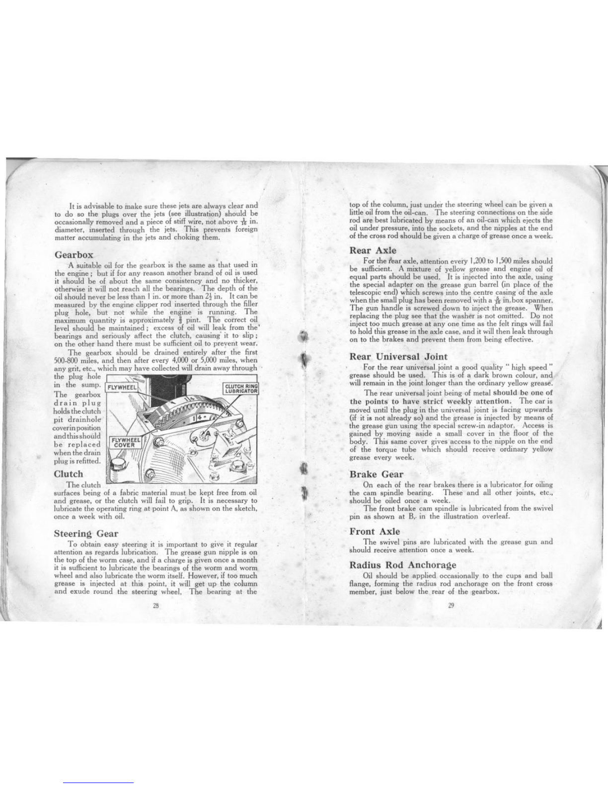
The gearbox should be drained entirely afte; the first
500-800miles. and then after every 4.000or 5.000miles, when
any grit. etc.. which may have collected willdrain away through'
the plug hole ,~
in the sump. FLYWHEEL
The gearbox ~
drain plug Iflll
holds theclutch
pit drainhole
coverinposition
and thisshould
be replaced
when the drain
plug is refitted.
Clutch
The clutch
surfaces being of a fabric material must be kept free from oil
and grease, or the clutch will fail to grip. It is necessary to
lubricate the operating ring at point A. as shown on the sketch,
once a week with oil.
{I
t
.
1
I
I
JSteering Gear
To obtain easy steering it is important to give it regular
attention as regards lubrication. The grease gun nipple is on
the top of the worm cas.e,and if a charge is given once a month
it is sufficient to lubricate the bearings of the worm and worm
wheel and also lubricate the worm itself. However, if too much
grease is injected at this point, it will get up the column
and exude round the steering wheel. The bearing at the
.,
~28
.
top of the column. just under the steering wheel can be given a
little oil from the oil-can. The steering connections on the side
rod are best lubricated by means of an oil-can which ejects the
oil undei pressure. into the sockets, and the nipples at the end
of the cross rod should be given a charge of grease once a week.
Rear Axle
For the fear axle, attention every 1.200to 1.500miles should
be sufficient. A mixture of yellow grease and engine oil of
equal parts should be used. It is injected into the axle. using
the special adapter on the grease gun barrel (in place of the
telescopic end) which screws into the centre casing of the axle
when the small plug has been removed with a -firin.box spanner.
The gun handle is screwed down to inject the grease. When
replacing the plug see that the washer is not omitted. Do not
inject too much grease at anyone time as the felt rings will fail
to hold this grease in the axle case. and it will then leak through
on to the brakes and prevent them from being effective.
Rear Universal Joint
For the rear univ~r5aLjoint a good quality" high speed ..
grease should be used. This is of a dark brown colour. and
will remain in the joint longer than the ordinary yellow grease.
The rear universal joint being of metal should be one of
the points to have stricf weekly attention. The car is
moved until the plug in the universal joint is facing upwards
(if it i. not already so) and the grease is injected by means of
the grease gun using the special screw-in adaptor. Access is
gained by moving aside a small cover in the floor of the
body. This same cover gives access to the nipple on the end
of the torque tube which should receive ordinary yellow
grease every week. .
Brake Gear
On each of the rear brakes there is a lubricator for oiling
the cam spindle bearing. These and all other joints, etc.,
should be oiled once a week.
The front brake cam spindle is lubricated from the swivel
pin as shown at B,. in the illustration overleaf.
,Front Axle
The swivelpins are lubricated with the grease gun and
should receiveattentiononce a week.
Radius Rod Anchorage
Oil should be applied occasionally to the cups and ball
flange. forming the radius rod anchorage on the front cross
member. just below the rear of the gearbox.
29
~
-
-!
'I
i.
I
'.
~
1111
i~,
Il
l'
".1
~
It is advisable to make sure these jets are always clear and
to do so the plugs over the jets (see illustration) should be
occasionally removed and a piece of stiff wire, not above ~in.
diameter, inserted through the jets. This prevents foreign
matter accumulating in the jets and choking them.
I'
I'
i
,I
"
Gearbox
'A;;;;:itable oil for the g~arbox is the same as'that used in
the engine; but if for any reason another brand of oil is used
it should be of about the same consistency and no thicker,
otherwise it will not reach all the bearings. The depth of the
oil should never be less than I in. or more than 2! in. It can be
measured by the engine clipper rod inserted through the filler
plug hole, but not while the engine is running. The
maximum quantity is approximately ipint. The correct oil
level should be maintained; excess of oil will leak from the'
bearings and seriously affect the clutch, causing' it to slip;
on the other hand there must be sufficient oil.to prevent wear.
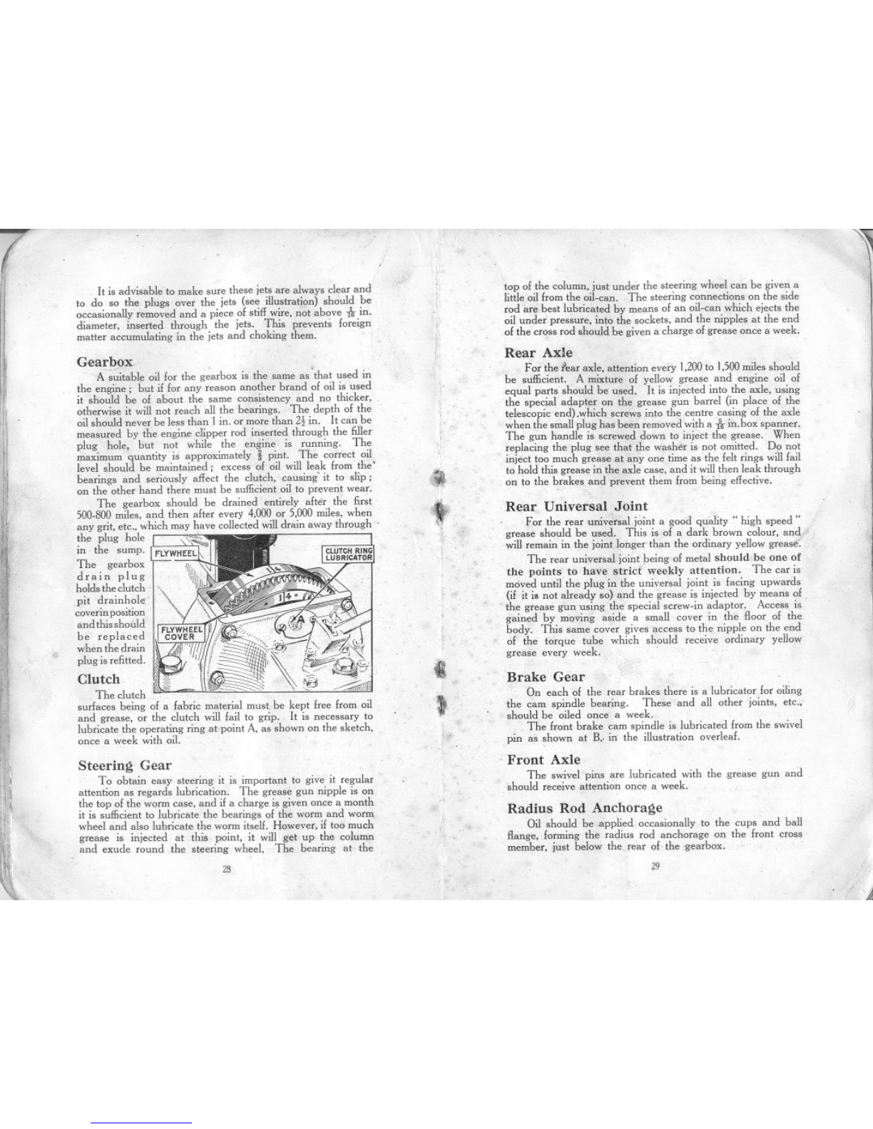
The g~arbox should be drained entirely after the fir~t
500-800miles, and. then after every 4,000 or 5,000 miles, when
any grit, etc.. which may have collected will drain away through'
the plug hole 's,.
in the sump. FLYWHEEL
The gearbox 'Ill "'-'\i
drain plug If/II
holds the clutch
pit drainhole
coverin position
and this should
be replaced
when the drain
plug is refitted.
Clutch
The clutch
surfaces being of a fabric material must be kept free from oil
and grease, or the clutch will fail to grip. It is necessary to
lubricate the operating ring at point A, as shown on the sketch,
once a week with oil.
"
(
..
.t
,
k
«
t
Steering Gear
To obtain easy steering it is important to give it regular
attention as regards lubrication. The grease gun nipple is on
the top of the worm case, and if a charge is given once a month
it is sufficient to lubricate the bearings o(the worm and worm
wheel and also lubricate the worm itself. However, if too much
grease is injected at this point, it will get up the column
and exude round the steering wheel. The bearing at the
.,
I'
28
~
top of the column, just under the steering wheel can be given a
little oil from the oil-can. The steering connections on the side
rod are best lubricated by means of an oil-can which ejects the
oil under pressure, into the sockets, and the nipples at the end
of the cross rod should be given a charge of grease once a week.
Rear Axle
Forthe lear axle, attention every 1,200to 1.500miles should
be sufficient. A mixture of yellow grease and engine oil of
equal parts should be used. It is injected into the axle, using
the special adapter on the grease gun barrel (in place of the
telescopic end) .which screws into the centre casing of the axle
when the small plug has been removed with a forin. box spanner.
The gun handle is screwed down to inject the grease. When
replacing the plug see that the washer is not omitted. Do not
,inject too much grease at anyone time as the felt rings will fail
to hold this grease in the axle case, and it will then leak through
on to the brakes and prevent them from being effective.
Rear Universal. Joint
For the rear univ~i~aLjoint a good quality" high speed"
grease should be used. This is of a dark brown colour, and
will remain in the joint longer than the ordinary yellow grease.
The rear universal joint peing of metal should be one of
the poiuts to have strict' weekly attention. The car is
moved until the plug in the universal joint is facing upwards
(if it i. not already so) and the grease is injected by means of
.the grease gun using the special screw-in adaptor. Access is
gained by moving aside a small cover in the floor of the
body. This same cover gives access to the nipple on the end
of the torque tube which should receive ordinary yellow
grease every week. .
Brake Gear
On each of the rear brakes there is a lubricator for oiling
the cam spindle bearing. These and all other joints, etc.,
should be oiled once a week.
The front brake cam spindle is lubricated from the swivel
pin as shown at B,. in the illustration overleaf.
.Front Axle
The swivel pins are lubricated with the grease gun and
.should receive attention once a week.
Radius Rod Anchorage
Oil should be applied occasionally to the cups and ball
flange, forming the radius rod anchorage on the front cross.
member, just below the rear of the .gearbox.
29
,d

T
t'x
""
,
'
,
'
"."""
"
'. ..,
Shock Absorbers
The shock absorbers should be lubricated only after
dismantling them (see page 46).
Windscreen Wiper
A drop of thin oil should be occasionally applied to the
windscreen wiper mechanism-say. once a month. A small
screw (except in the Trico model) is removable from the top of
the casinl'l"llowing the oil to be injected.
Fan
The fan bearing requires a charge of grease once a month
through the nipple on the fan bracket.
Grease Nipples
If a grease nipple gets choked, unscrew and remove it.
It can usually be cleared by soaking it in paraffin or petrol.
and syringing either of these through it, but should it be found
impossible to clear it, fit a new nipple in its place.
.
GRE'SE
NIPPLE SWIVEL PIN
LOCKING PIN
Road Springs '
The ends of the road springs where they are attached to the
axles are provided with grease 'gun coimections, and should be
given a charge once a week if the car is continually used. After
a long period of use it is advisable to lubricate the leaves of the
spring with a warm mixture of white lead and tallow in equal
parts. This can best be applied with a stiff brush, the leaves
being eased apart by a screwdriver; first jack up the car.
not under the axles. nor the radius rods, but under the frame to
take the weight, off ,the springs. The rear of the car can be
jacked up one side at a time. The best point of the frame at
which to apply the jack is each end of the rear cross-member.
At the front, as there is only one transverse spring, the whole
of the car must be lifted, and as a safety measure, the rear wheels
should be .. scotched" to prevent the car running off the jack.
A short stiff bar is placed across the frame, just forward of the
engine oil reservoir, and behind the spring, and the jack lifts
the car from the centre of this bar. It will be necessary to block
the jack up for this work, with a' wood block, to avoid
necessitating an excessive lift.
.,
IThe front hoh io ",,"ion. showiog the grea.. pIng A,
BRAKE LEVER CONNECTION
"
grease-gun should not be
turned more than twice to
give the maximum charge
advisable.
Front Hubs
Remove the road wheel (see page 11). Turn the hub until
the plug" A" is at the top. Screw out the plug and screw
in the adapter which is provided in the' kit. '
Fill the hub with grease. It is important that the hubs are
not given too much grease, otherwise it will penetrate to the
brakes to render them ineffective. The handle of the
30
l
,
I
Rear Hubs
Remove the road
wheel. Turn the wheel
until the nipple" A" is
at the top. Inject grease
into the hub; if the handle
of the gun is given two
turns the grease will be
sufficient for ordinary
maintenance purposes.
A ,,"'on of the roarhub. sbowlug the
nipple A.
Other Points
Occasionally give a drop or so of oil to the engine control
joints. the door locks, the hood frame hinges, and all other
small working joints, This will keep them working smoothly,
without wear, which would ultimately cause rattle.
31
~
"
11
I
ELECTRICAL
EQUIPMENT
Never use the starting motor to propel the car, as it throws
too severe a strain on the battery and the motor.
If the engine does not start at the first attempt, do not press
the starter switch until the engine has come to rest. If this
precaution is not adopted, the starter ring teeth on the flywheel
cover, or the starter pinion teeth, may be damaged.
-
'II
I
i
THE lighting and starting units on the Austin Seven
car are arranged for wiring on the single wire system,
the return path of the current being provided by the
frame instead of a second wire. It is essential that all units
are in metallic contact with the frame.
Should difficulties arise that cannot be understood or
remedied from the information given below, application should
at once be made to the Austin Service Department or the
nearest service depot of the makers of the equipment (address
on page 51).
Dynamo
The dynamo is a simple self-regulating third brush machine.
The only parts calling for any attention are the commutator and
brushes, which are readily accessible whe,! the clip secured
cover is removed. The commutator surface must be kept clean
and free from any oil or brush dust. It may be cleaned with
ordinary soft rag but if it has been neglected use fine glass paper.
Blow away any carbon dust, see that the carbon brusbes are
wearing evenly and move freely in their holders. To fit a new
brush it is only necessary to release the brusb tag, hold back
tbe brush trigger and then withdraw the worn brush from its
holder. The new brush can then be fitted by reversing the
above operations.
The dynamo-bearings are packed with grease before leaving
the works and need very little attention. A few diops of
ordinary engine oil, however, may be added through the
lubricator near the mounting flange, say every 1,000 miles.
The owner is cautioned that far more trouble is caused
by excessive oiling than by too little.
Starting Motor
The commutator is accessible on removing the clip secured
cover. The unit requires very little attention beyond keeping
the commutator clean and free from oil, brush dust, etc.. as in
the case of the dynamo. Before starting f~omcold do not neglect
the preliminary precautions that you would observe if starting by
hand, such as flooding the carburetter, etc, Remember that
although the starter will turn the engine over, however stiff, it
is advisable to crank the engine over by hand two or three
revolutions as this will considerably diminish the load for starting.
If the starter pinion jams in mesh with the flywheel ring
when operating the starting motor switch, usually it can be
released by putting the gear lever into top gear, and moving the
car bodily backward and forward. If this plan is ineffectual
the starter will have to be dismantled.
Switchbox
The switchbox houses two switches controlling the lighting
and charging circuits, a centre.zero ammeter and the ignition
warning light. The charging switch is also arranged so that
in the" off " position it breaks the ignition circuit, thus obviating
the necessity of ;, separate switch.
I
I
I
I
I
,
,
,
i
Switch Positions
Each switch has three positions. Left hand switch (I)
" OFF" position-dynamo not charging and ignition off.
(2) "Summer! Charge" position-ignition operating and
dynamo charging with half its normal output. (3) "Winter
Full C" position-ignition operating and dynamo charging
with its full output. Right hand switch (I)" OFF" position
-all lamps off. (2)" S " position-headlamps dim and tail
lamp. (3)" H " position-headlamps bright, and tail lamp.
Switching on lamps automatically puts the dynamo on
full charge.
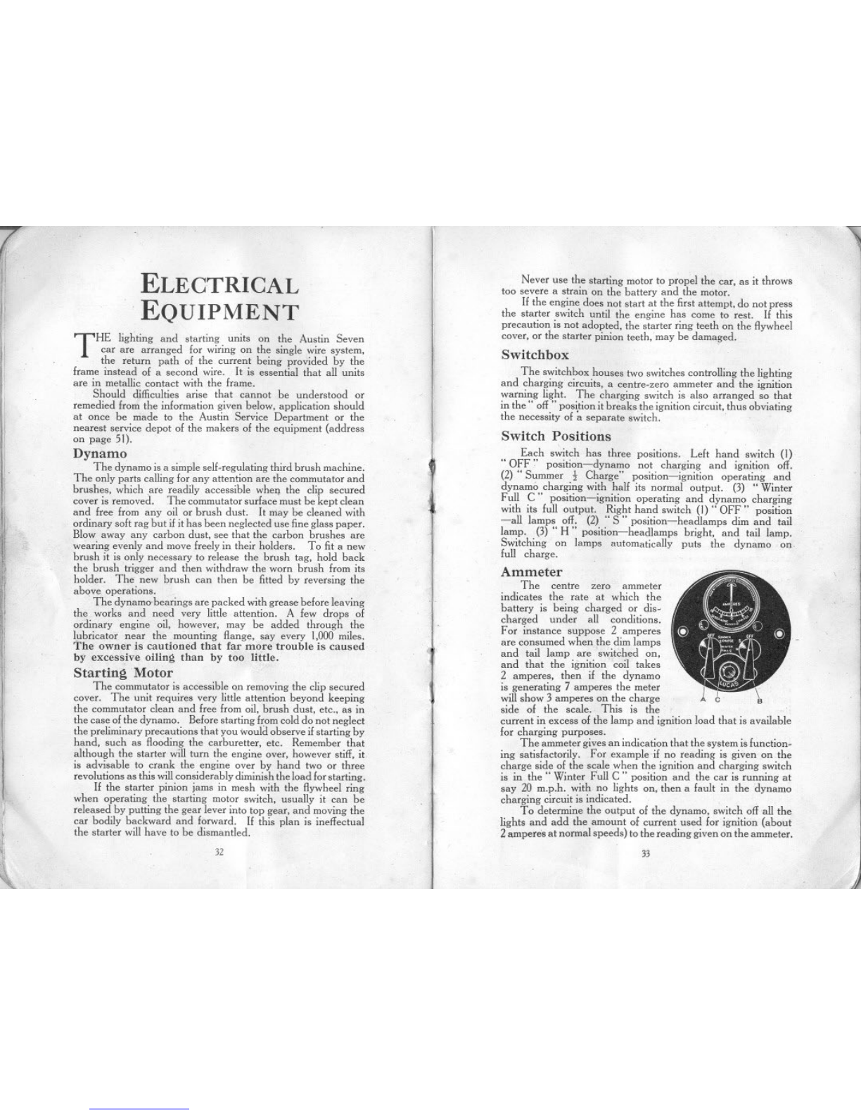
Ammeter
The centre zero ammeter
indicates the rate at which the
battery is being charged or dis-
charged under all conditions.
For instance suppose 2 amperes
are consumed when the dim lamps
and tail lamp are switched on,
and that the ignition coil takes
2 amperes, then if the dynamo
is generating 7 amperes the meter
will show 3 amperes on the charge
side of the scale. This is the
current in excess of the lamp and ignition load that is available
for charging purposes.
The ammeter gives an indication that the system is function-
ing satisfactorily. For example if no reading is given on.the
charge side of the scale when the ignition and charging switch
is in the" Winter Full C " position and the car is running at
say 20 m.p.h. with no lights on, then a fault in the dynamo
charging circuit is indicated. .
To determine the output of the dynamo, switch off all the
lights and add the amount of current used for ignition (about
2amperes at normal speeds) to the reading given on the ammeter.
32 33
This manual suits for next models
1
Table of contents
Other Austin Automobile manuals


