Autani EnergyCenter autaniNet/EnOcean Bridge User manual
Quick Start Guide
autaniNet/EnOcean Bridge
© 2019 Autani, All Rights Reserved.

Page | 2
Table of Contents
1. Introduction.............................................................................................................................. 3
1.1. HVAC Application .................................................................................................................................................... 3
1.2. General Pass-through Application .......................................................................................................................... 3
2. System Overview ...................................................................................................................... 4
3. Specifications............................................................................................................................ 6
3.1. EnOcean Bridge....................................................................................................................................................... 6
3.2. EnOcean Temperature Sensor ................................................................................................................................ 6
3.3. EnOcean Temperature + Humidity Combo Sensor ................................................................................................. 6
3.4. Pressac Temperature + Humidity + CO2Combo Sensor ......................................................................................... 6
4. Mounting the EnOcean Bridge................................................................................................... 7
5. Connecting EnOcean Bridge to Thermostat ............................................................................... 7
5.1. Mounting the Thermostats ..................................................................................................................................... 8
6. Connect EnOcean Bridge to Remote Sensors ............................................................................. 9
6.1. Pairing Locally ......................................................................................................................................................... 9
6.2. Commissioning Remotely...................................................................................................................................... 12
6.2.1. Commissioning EnOcean Bridge................................................................................................................ 12
6.2.2. Commissioning Remote Sensors ............................................................................................................... 15
6.2.3. Commissioning Thermostats..................................................................................................................... 19
7. Mounting the EnOcean Remote Sensors.................................................................................. 21
8. Mounting the Pressac Remote Sensor ..................................................................................... 22
9. General Application ................................................................................................................ 23
This document contains the Proprietary and Confidential Information of Autani, LLC. Any use of this information without the expressed written consent of Autani, LLC
is prohibited. Copyright Autani, LLC, 2010-2019. All rights reserved. Please refer to www.autani.com/legal for licensing, intellectual property, and other legal notices
and information.
Page | 3
1. Introduction
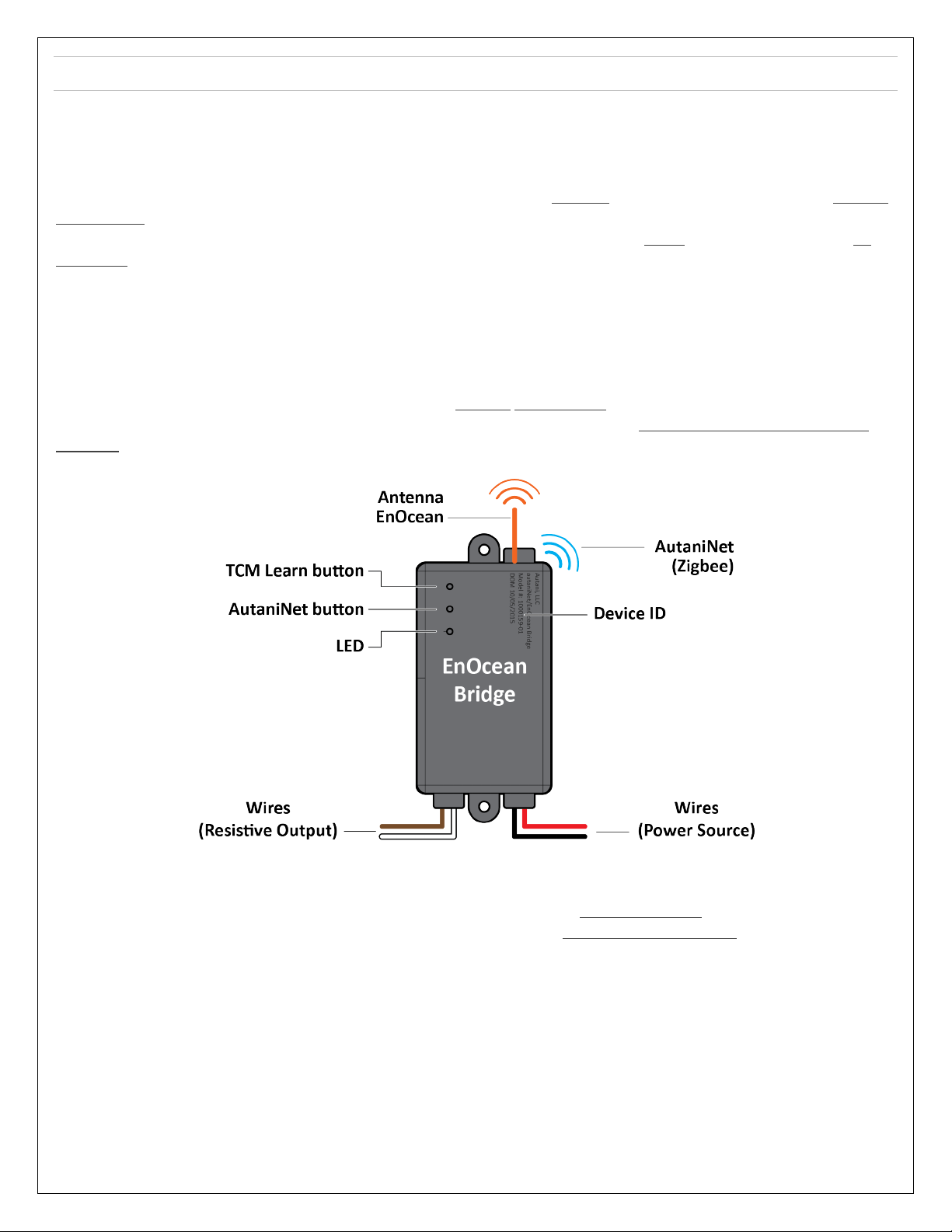
The EnOcean Bridge acts as a communication bridge between the Autani System and EnOcean devices for the following
applications.
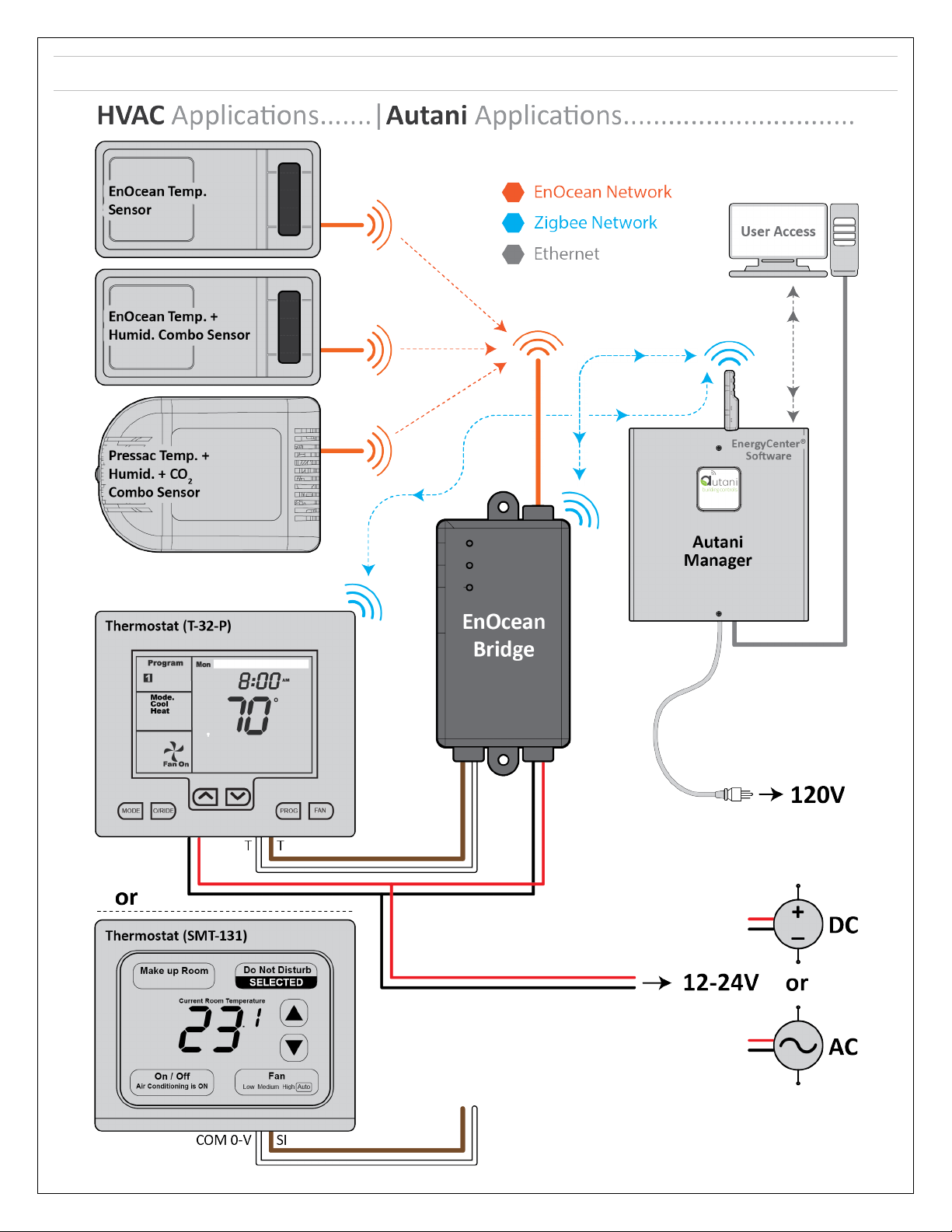
1.1. HVAC Application
In general, the EnOcean Bridge will receive temperature readings from multiple remote sensors and provide an average
temperature reading to the thermostat. Based on the average readings from the EnOcean Bridge, the thermostat would
trigger the HVAC system to maintain the temperature of an area. If the system has a single remote sensor, there is no
averaging, and the gateway would transmit only the single remote sensor data to the thermostat.
Parallel to the above bridging process, the EnOcean Bridge will also allow the devices to be connected to the Autani
Manager’s EnergyCenter® Software, via the AutaniNet wireless network. The software can commission the remote
sensors and also generate reports for all the devices.
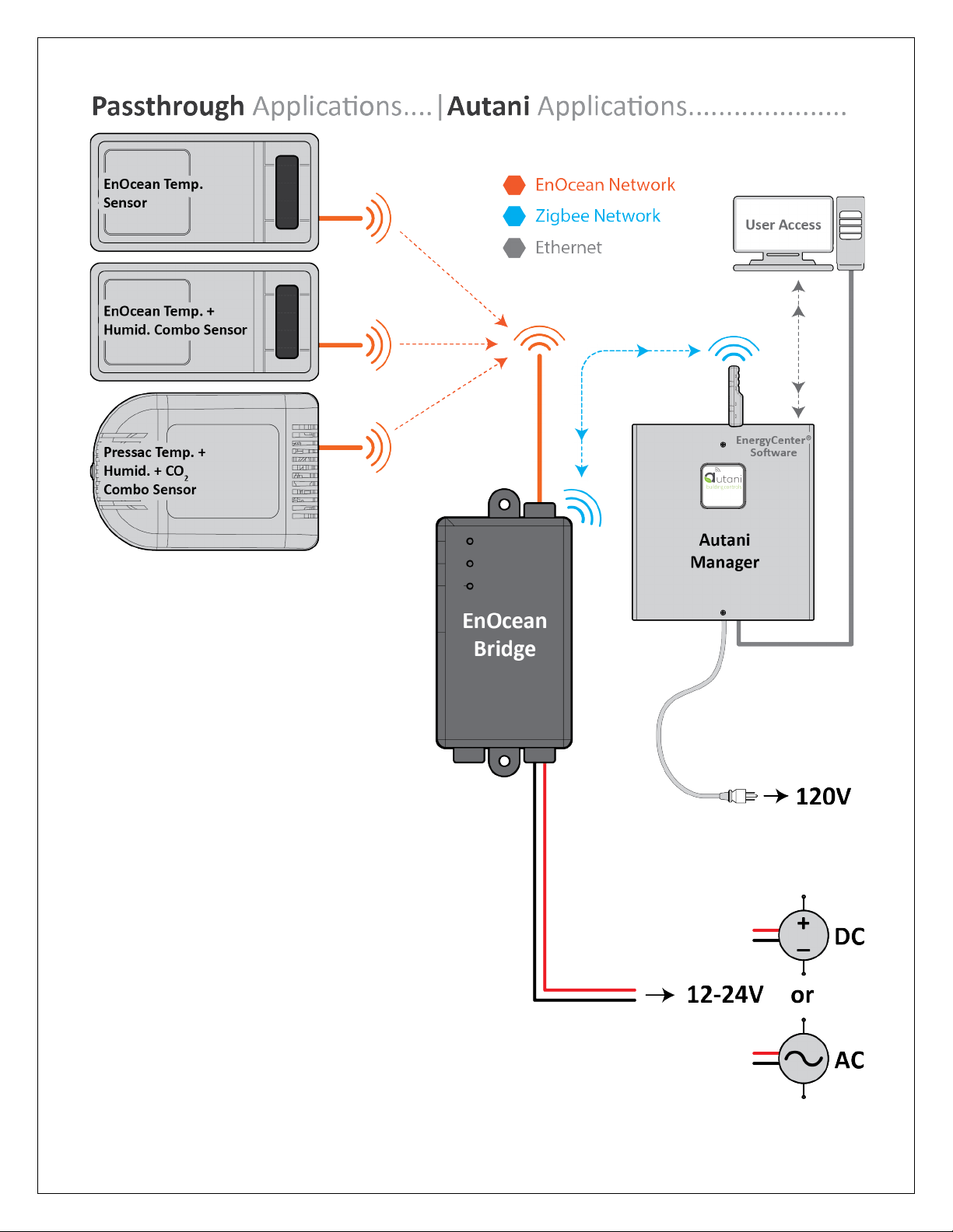
1.2. General Pass-through Application
Another major functionality of the EnOcean Bridge is the General Pass-through feature in the absence of a thermostat.
The sensor readings received by the EnOcean Bridge are directly transmitted to the Autani Manager’s EnergyCenter®
Software, via the AutaniNet wireless network. The pass-through application can also be used with other select EnOcean
sensors that Autani has certified capability with.
The EnOcean Bridge can locally pair with remote temperature sensors, or they can be remotely commissioned
through EnergyCenter® Software.
The EnOcean Bridge can locally pair with the following SENSORS inside HVAC Application; it also supports other
types of EnOcean devices (like motion or contact sensors) within the Pass-through Application.
•EnOcean Temperature Sensor (Model: EEP: A5-02-05).
•EnOcean Temperature + Humidity Combo Sensor (Model: EEP: A5-04-01).
•Pressac Temperature + Humidity + CO2Combo Sensor (Model: EEP: A5-09-04).
NOTE: Each EnOcean Bridge can map up to ten remote sensors within a range of 80 - 100 ft LOS.
The EnOcean Bridge supports any thermostat with a 10k ohm type 2 thermistor. This Quick Start Guide describes
the connection with following thermostats:
•Autani SMT-131.
•Autani T-32-P.
Page | 4
2. System Overview
Page | 5
Page | 6
3. Specifications
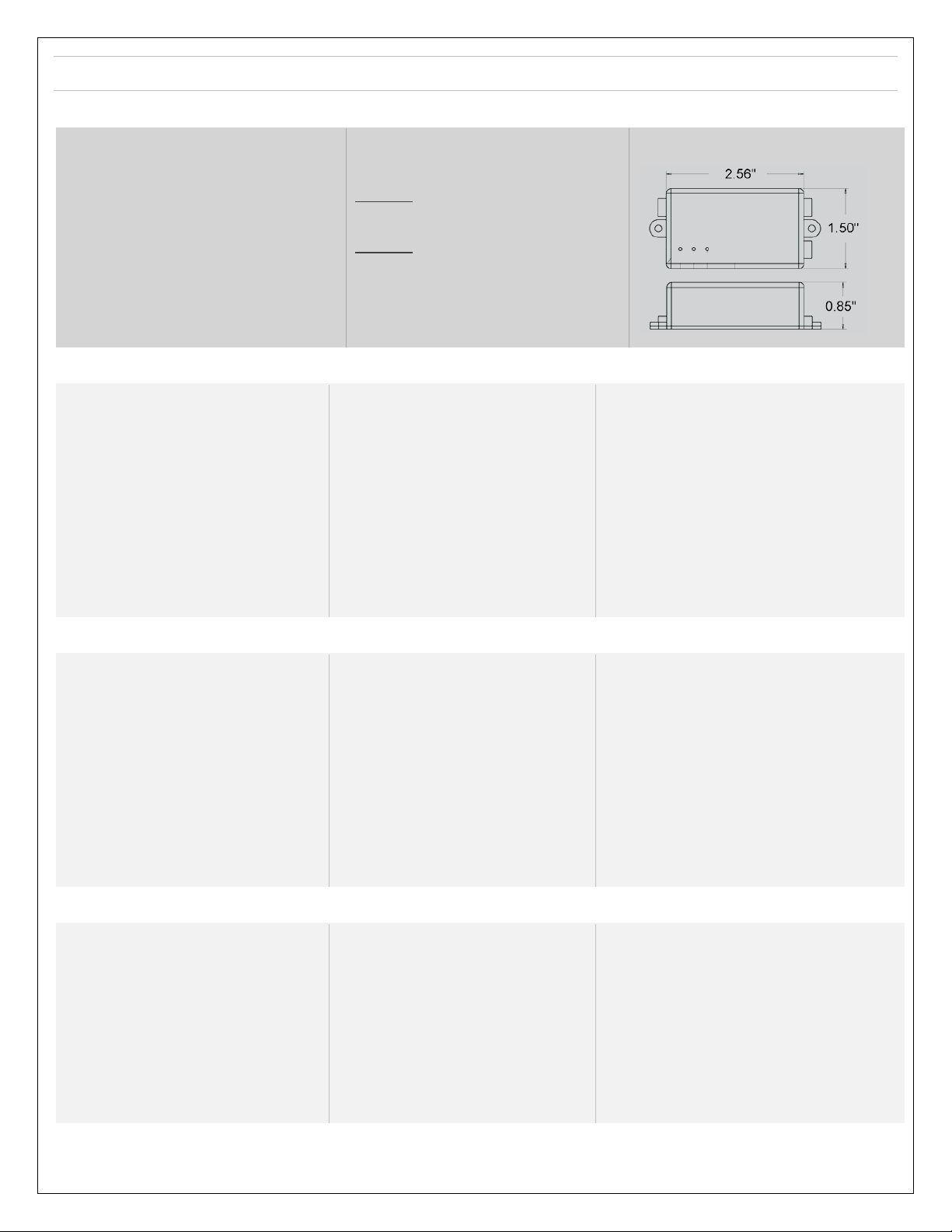
3.1. EnOcean Bridge
Electrical
Input Voltage: 12-24V AC/DC
Environmental
Operating Temperature: 0° to 60°C
Storage Temperature: -25° to 80°C
Range
AutaniNet: Approx. 600’ LOS transmit/receive
EnOcean: Approx. 80-100’ LOS transmit/receive
(see individual device)
Radio Network (AutaniNet)
IEEE 802.15.4-2003 2.4GHz ISM
Radio Network (EnOcean)
EnOcean 902 MHz
Regulatory Approvals
Module 1:
FCC ID: V8NWAT1000153 and SZVSTM300U
IC: 7737A-WAT1000153 and 5713A-STM300U
Module 2:
FCC ID: SZV-STM300U and SZVSTM300U
IC: 5713A-STM300U and 5713A-STM300U
Ordering Information
SKU: A06-01-0440-01
Description: AutaniNet/EnOcean Bridge
Physical
Dimensions (HxWxD): 2.56 x 1.5 x 0.85 in
3.2. EnOcean Temperature Sensor
Power supply
Solar cell
Antenna
Whip or helix antenna
Frequency
868.3 MHz (STM 33x) / 902.875 MHz (STM 33xU)
Radiated output power
STM 330 / 331: max. 6.4 dBm / 5 dBm (EIRP)
331U and STM 333U: typ 92 dBμV/m / 99 dBμV/m
Data rate / Modulation type
125kBit/s / ASK (868.3MHz) / FSK (902.875MHz)
Start-up time with empty energy storage
typ. <2.5 min @ 400 lux, 25 °C
Initial operation time in darkness @25°C1
Typ. 4 days, if energy storage fully charged
wake-up every 100 s, transmission every 1000 s
on average.
Input Channels
Internal: temperature sensor, LRN button
External via 20 pin connector: occupancy button,
set point dial, HSM 100
Temperature sensor
Measurement range 0-40 °C, resolution 0.16 K
Accuracy typ. ±0.5 K between 17 °C and 27 °C,
typ. ±1 K between 0 °C and 40°C
Transmission indicator
1x LED
EnOcean Equipment profiles
Configurable EEPs: A5-02-05, A5-02-30, A5-10-05,
A5-10-03 and with HSM 100: A5-04-01, A5-10-10,
A5-10-12
Module dimensions
43 x 16 x 8 mm
Operating temperature1
-20 up to +60 °C
Radio approvals
STM 330 (max. radiated power +6.4dBm whip): RED (EU)
STM 331 (max. radiated power+5 dBm helix) : RED (EU)
STM 331U, 332U and STM 333U: FCC (US) / ISED (CA)
3.3. EnOcean Temperature + Humidity Combo Sensor
Power supply
Solar cell
Antenna
Whip or helix antenna
Frequency
868.3 MHz (STM 33x) / 902.875 MHz ( STM 33xU)
Radiated output power
STM 330 / 331: max. 6.4 dBm / 5 dBm (EIRP)
331U and STM 333U: typ 92 dBμV/m / 99 dBμV/m
Data rate / Modulation type
125kBit/s / ASK (868.3MHz) / FSK (902.875MHz)
Start-up time with empty energy storage
typ. <2.5 min @ 400 lux, 25 °C
Initial operation time in darkness @25°C1
Typ. 4 days, if energy storage fully charged wake-
up every 100 s, transmission every 1000 s on
average
Input Channels
Internal: temperature sensor, LRN button
External via 20 pin connector: occupancy button,
set point dial, HSM 100
Temperature sensor
Measurement range 0-40 °C, resolution 0.16 K
Accuracy typ. ±0.5 K between 17 °C and 27 °C,
typ. ±1 K between 0 °C and 40°C
Transmission indicator
1x LED
EnOcean Equipment profiles
Configurable EEPs: A5-02-05, A5-02-30, A5-10-05,
A5-10-03 and with HSM 100: A5-04-01, A5-10-10,
A5-10-12
Module dimensions
43 x 16 x 8 mm
Operating temperature1
-20 up to +60 °C
Radio approvals
STM 330 (max. radiated power +6.4dBm whip): RED (EU)
STM 331 (max. radiated power+5 dBm helix) : RED (EU)
STM 331U, 332U and STM 333U: FCC (US) / ISED (CA)
3.4. Pressac Temperature + Humidity + CO2Combo Sensor
Measurement Range
CO20 to 2550 PPM
Temperature 0 °C to +51 °C
Humidity 0 to 100% RH
Accuracy
CO2+/- 125PPM
Temperature +/- 0.5 °C
Humidity +/- 5% RH
Sampling Rate
Can be fixed to 15 minutes or can dynamically
adjust between 5 and 15 minutes dependent on
power source and light conditions
Repeater : No
Telegram
4BS
Environment
IP2X
Battery* Back Up
3.6v A size non rechargeable Lithium
Enclosure Material
ABS
Calibration
Manual or auto recalibrates every 8 days
Solar
Amorphous Silicon Solar Cells
Operating Temperature Range
-5 °C to +60 °C
Storage Temperature Range
-20 °C to +55 °C
Sensor Response Time
Telegram transmission is within 2 seconds of
measurement
Dimensions: 115 x 80 x 35 mm approx.
EEP : A5-09-04
1Full performance is achieved after several days of operation (up to two weeks) at a good illumination level. Performance degrades over life time, especially if energy storage is exposed to
higher temperatures. Each 10 K drop in temperatures doubles the expected life span.
*Battery life dependant on ambient light conditions.
Page | 7
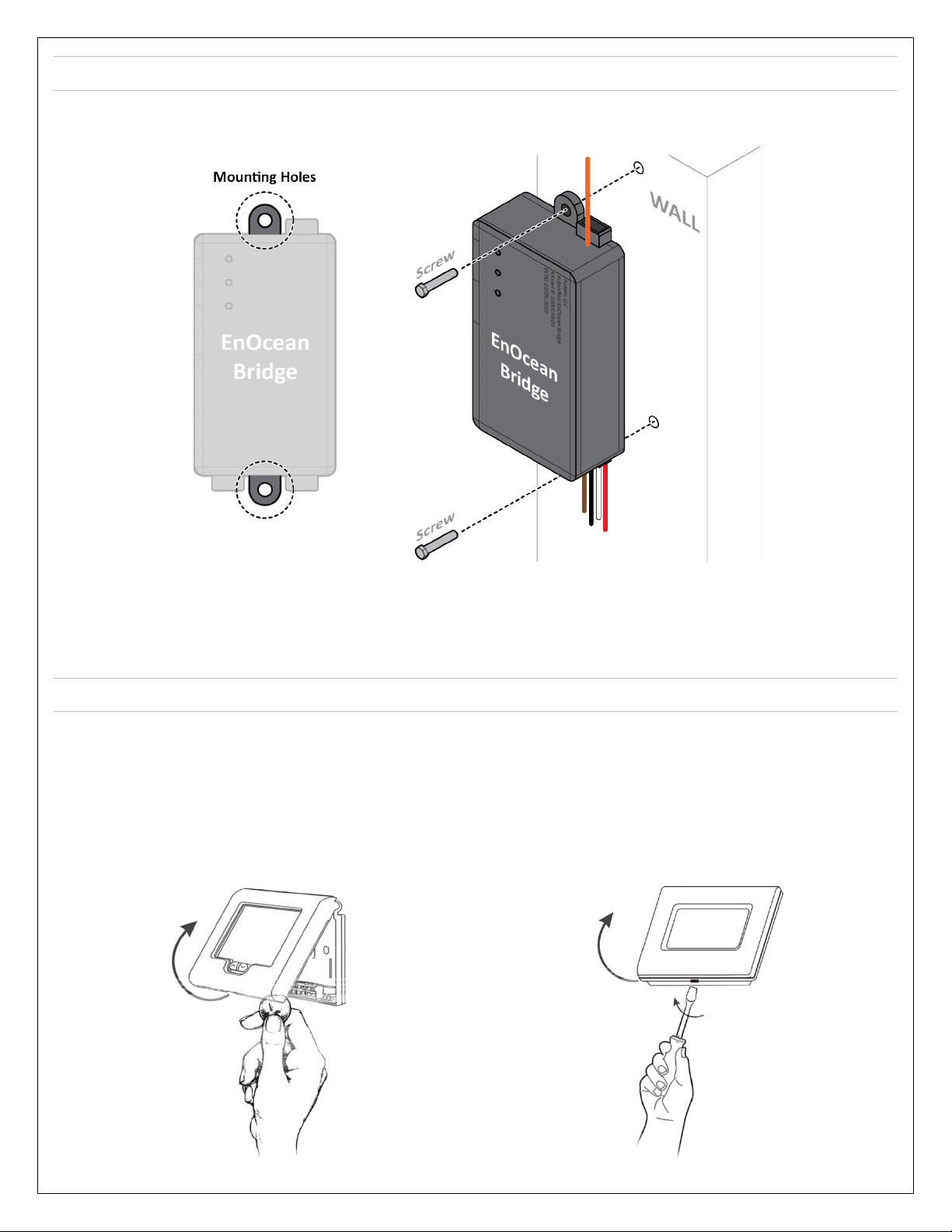
4. Mounting the EnOcean Bridge
1. Mount the EnOcean Bridge in a convenient location at a desired distance from the ground, and within a range of 80-
100 ft to the remote sensors.
2. There are two mounting holes provided on the EnOcean Bridge. Locate a place to mount the EnOcean Bridge, mark
the holes to be drilled, and drill two holes on the wall.
3. Place and align the EnOcean Bridge mounting holes with the holes on wall. Insert screws on both ends of the Bridge
and torque tighten the screws.
5. Connecting EnOcean Bridge to Thermostat
CAUTION: Ensure the thermostat is not connected to the main line or power source (24VDC).
1. If the thermostat is already mounted to a wall, unmount the thermostat to proceed. (Please refer to the Installation
Manual of respective thermostat.)
2. Locate the release slot on the bottom of the thermostat. Insert a small coin or a flat screwdriver and gently twist to
open the sensor housing upside. Handle the sensor housing gently, not to stress the LCD or bend the terminal
connector pins.
Thermostat: T-32-P
Thermostat: SMT-131
Page | 8
NOTE: After each connection detailed in below procedure, ensure the terminal connections are secure by fastening
a screw into the terminals. DO NOT over tighten.
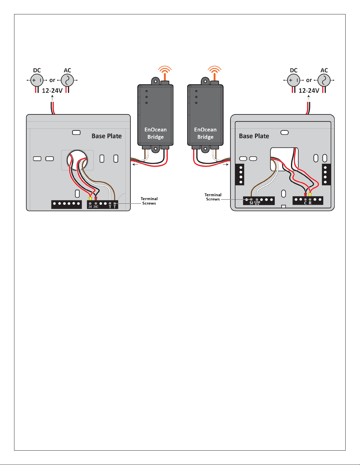
3. Except for the antenna, insert all the wires from the EnOcean Bridge into the large hole provided on the Base Plate
of Thermostat. (NOTE: INSERT THE WIRES FROM THE BACKSIDE OF THE BASE PLATE).
Thermostat: T-32-P
4. Connect the Red wire from EnOcean Bridge with the
Red wire from thermostat. Insert the connected wires
into the terminal 24 of the thermostat.
5. Connect the Black wire from EnOcean Bridge with the
Black wire from thermostat. Insert the connected wires
into the terminal 24C of the thermostat.
6. Connect the White wire from EnOcean Bridge to the
first TT terminal of the thermostat.
7. Connect the Brown wire from EnOcean Bridge to the
second TT terminal of the thermostat.
Thermostat: SMT-131
4. Connect the Red wire from EnOcean Bridge with the
Red wire from thermostat. Insert the connected wires
into the terminal Rof the thermostat.
5. Connect the Black wire from EnOcean Bridge with the
Black wire from thermostat. Insert the connected wires
into the terminal Cof the thermostat.
6. Connect the White wire from EnOcean Bridge to the
COM 0-V terminal of the thermostat.
7. Connect the Brown wire from EnOcean Bridge to the SI
terminal of the thermostat.
8. Connect the HVAC and others wires to thermostat. (Please refer to the Installation Manual of respective
thermostat.)
9. Mount the thermostat to the wall. (Please refer to the Installation Manual of respective Thermostat.)
10. Gently close the sensor housing onto the base plate of Thermostat and proceed to section “Connect EnOcean Bridge
to Remote Sensors” of this guide to pair with remote sensors.
5.1. Mounting the Thermostats
This Quick Start Guide will not cover mounting instructions for the thermostat. For instructions on thermostat
installation, please refer to the installation manual of respective thermostat on the Autani web portal.
NOTE: The brown and white Resistive Output wires MUST be shielded from the 24V wire run, using dedicated conduit
and shielding as needed. Failure to do so will cause an incorrect temperature reading into the thermostat from the
remote sensors.
Page | 9
6. Connect EnOcean Bridge to Remote Sensors
The EnOcean Bridge can pair with the sensors locally or be commissioned remotely through the EnergyCenter® software.
6.1. Pairing Locally
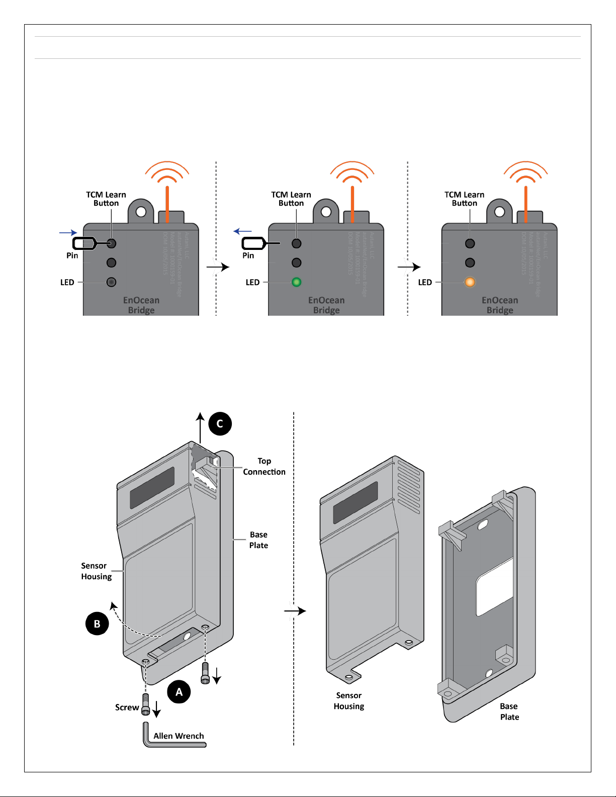
1. Put the EnOcean Bridge into Learning Mode
a. Insert a pin into the TCM-LRN (learn) button.
b. Press and hold the TCM-LRN button until the Green LED turns on (after about 2-3 seconds).
c. Release the button. The LED will turn Amber.
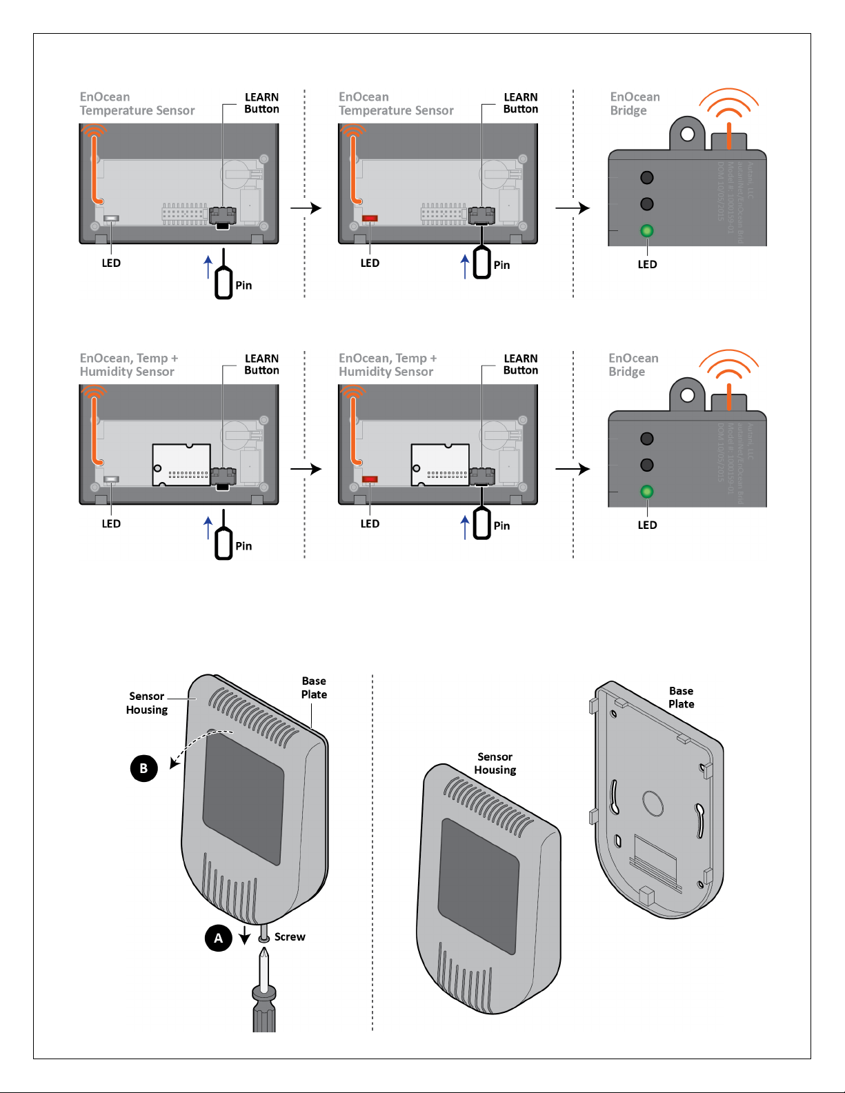
2. Pair the EnOcean Temperature Sensor to the EnOcean Bridge
NOTE: Pair the sensor within 30 seconds. The 30 second timer resets when a new device is mapped.
WARNING: Handle the sensor housing gently while dismantling the sensor to avoid damaging internal parts.
a. Use a 1/16” Allen Wrench to access the Learning Button by removing the screws from the bottom of the sensor
housing. Slightly open the bottom of the sensor housing and then slide it up to disconnect it from the top of the
base plate.
Page | 10
b. Press the Learn Button on the sensor housing. If a message is sent, the Red LED will flash on the sensor. If the
Bridge has received the message, its LED will briefly turn Green.
3. Pair the EnOcean Temp + Humidity Combo Sensor to the EnOcean Bridge
a. Repeat step 2. NOTE: Pair the sensor within 30 seconds. The 30 second timer resets when a new device is mapped.
4. Pair the Pressac Temp + Humidity + CO2Combo Sensor to the EnOcean Bridge
NOTE: Pair the sensor within 30 seconds. The 30 second timer resets when a new device is mapped.
WARNING: Handle the sensor housing gently while dismantling the sensor to avoid damaging internal parts.
a. Use a Philips screwdriver to access the Learning Button by removing the screws from the bottom of the sensor
housing. Slightly open the top of the sensor housing and disconnect it from the base plate.
Page | 11
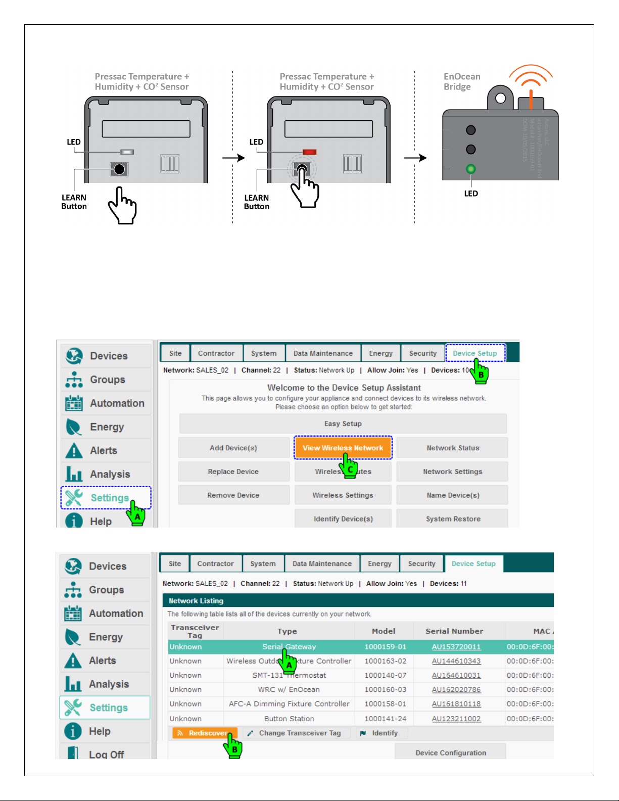
b. Press the Learn Button on the sensor housing. If a message is sent, the Red LED will flash on the sensor. If the
Bridge has received the message, its LED will briefly turn Green.
NOTE: WAIT AT LEAST 30 SECONDS FOR LEARN MODE TO EXIT.
5. Verify sensors were paired (when the EnOcean Bridge is not in Learn Mode)
a. Press the Learn Button on the sensor.
b. The EnOcean Bridge LED should briefly turn solid green.
NOTE: If the EnOcean Bridge was already connected to AutaniNet before the local binding, then the user must
‘Rediscover’ the EnOcean Bridge before the local bindings will show from the Bridges GUI within EnergyCenter®.
A device can be rediscovered from Settings > Device Setup > View Wireless Network accordingly’.
Select the Gateway and click on Rediscover button.
Page | 12
6.2. Commissioning Remotely
The EnOcean Bridge and the remote sensors can also be paired and commissioned through the Autani Manager’s
EnergyCenter® Software.
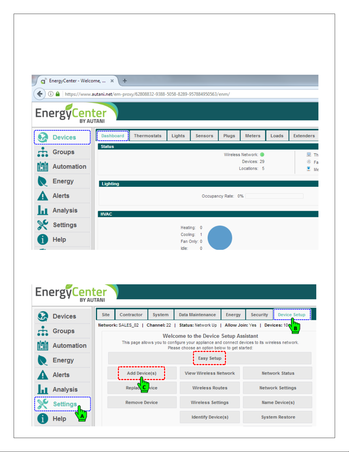
1. Login to the Autani web portal using the credentials provided.
2. By default the browser will load the Device page with the Dashboard data. (For more information on the User
Interface, please refer to the Help section of EnergyCenter.)
6.2.1. Commissioning EnOcean Bridge
1. To add the EnOcean Bridge, click Settings > Device Setup > Add Device(s).
NOTE: If the Add Device(s) button is not available, proceed with the Easy Setup wizard.
Page | 13
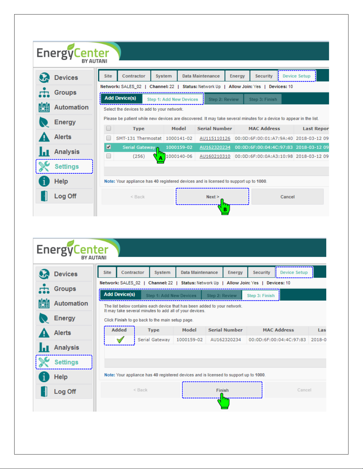
2. The Add Device(s) page loads. Select the EnOcean Bridge from the list of devices and click Next.
NOTE: The system may need a moment to search for and list nearby devices.
3. Review the selected device and click Next.
4. The last screen confirms the addition of an EnOcean Bridge to the system. Click Finish to complete the process.
5. The EnOcean Bridge is now available inside the Devices Section under Extender Tab.
Page | 14
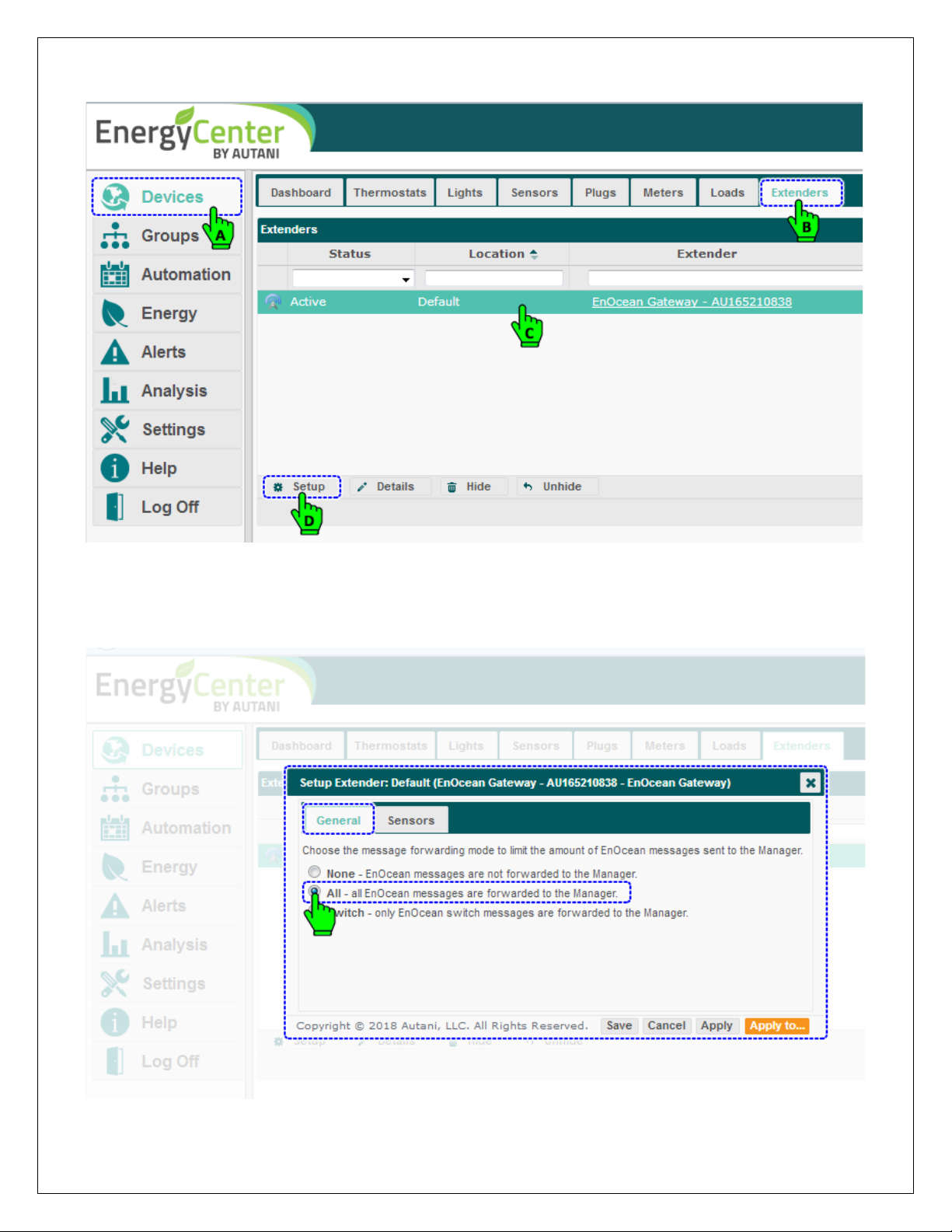
6. To commission the remote sensors, click Devices and then click the Extender tab, select the 'EnOcean Gateway –
AU165210838' from the list, and click Setup.
7. The Setup Extender pop-up menu appears containing General and Sensors tabs. The General tab is selected by
default and contains three options for the Pass-through feature of EnOcean Bridge. Here the user can choose to
limit the amount of EnOcean messages sent to Autani Manager.
8. Select the option “All - all EnOcean messages are forwarded...” to forward all the messages. Save & Apply.
Page | 15
6.2.2. Commissioning Remote Sensors
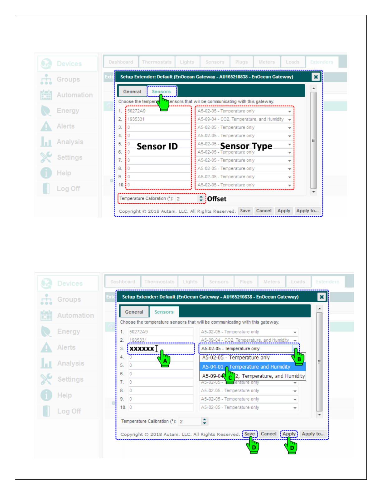
1. Click on the Sensors tab, which will allow the user to commission the sensors. The tab should have already listed the
sensors added during Learning Mode, or the user can add them directly to the list and set the type of sensing.
•There are two columns inside the Sensor tab, one for Sensor ID and another for Sensor Type.
•NOTE: There is also a feature to calibrate the averaged temperature if the averages are not inline. This can be
done by providing the offset to the average by few degrees; this offset is stored inside the EnOcean Bridge.
2. To commission another sensor, locate the next available empty list, and place the cursor inside the ID field, and key
in the Sensor ID. Select the type of sensor from the drop down list. Click Save followed by Apply button.
Page | 16
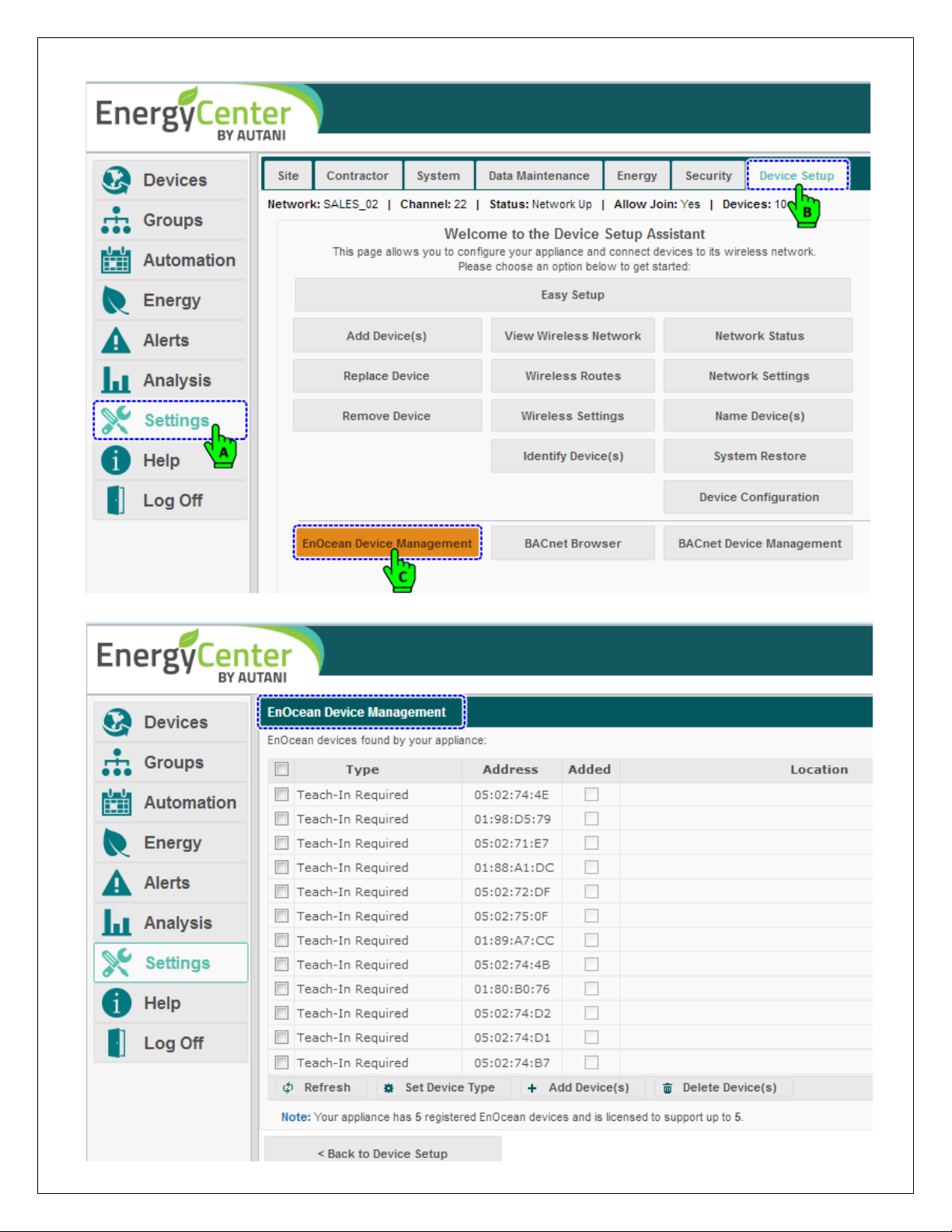
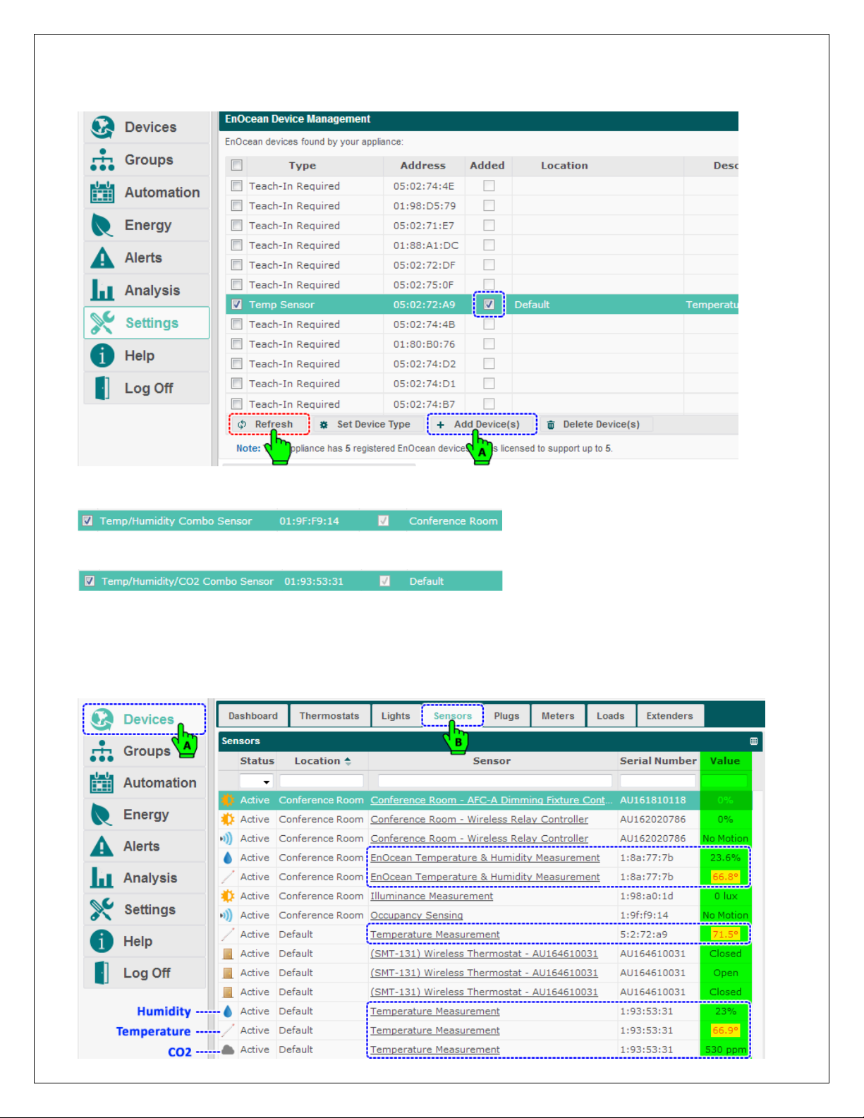
3. Start adding the sensors to the EnergyCenter® system. Click Settings > Device Setup >EnOcean Device Management.
4. The EnOcean Device Management page, lists all the EnOcean devices within the range of EnOcean Bridge.
Page | 17
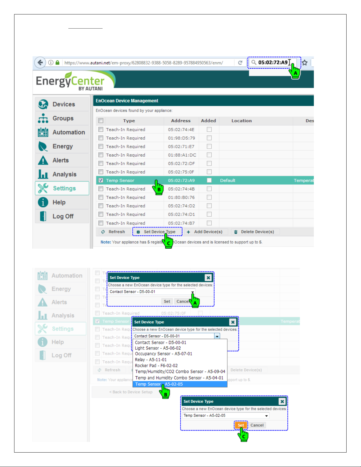
5. Search/find a Temp Sensor in the list using Serial Number/Address. Select the desired sensor and click on
Set Device Type to set the type of sensor.
NOTE: The user can skip setting the device type if the sensor is already set with a device type while pairing locally, or
if it is set inside the Sensor tab.
6. The Set Device Type pop-up menu appears; select the “Temp Sensor - A5-02-05” from the drop down list and
click Set button to set the device type.
Page | 18
7. With the Temp Sensor still selected, click Add Device(s) button to add the Temp Sensor to EnergyCenter System.
NOTE: If the sensor is added, the check box in the Added column should be in checked state, or else click the
Refresh button for the checked state to appear, confirming the addition of sensor to the system.
8. Repeat steps 5-7 to add Temp + Humidity Sensor to the system. Ensure the device type is set to “Temp and
Humidity Combo Sensor - A5-04-01”.
9. Repeat steps 5-7 to add Temp + Humidity + CO2Sensor to the System. Ensure the device type is set to
“Temp/Humidity/CO2Combo Sensor - A5-09-04”.
10. The Sensors added to the system should soon start reporting their values inside the Sensors tab.
11. Along with the temperature values, other values like humidity, CO2, illuminance, etc., are also reported by respective
sensors. These values are further utilized by EnergyCenter® software to generate reports as needed. This is one of
the important features of pass-through application.
12. Click Devices and then click Sensors tab; all the sensors added to the system will report their values in Value column.
Page | 19
6.2.3. Commissioning Thermostats
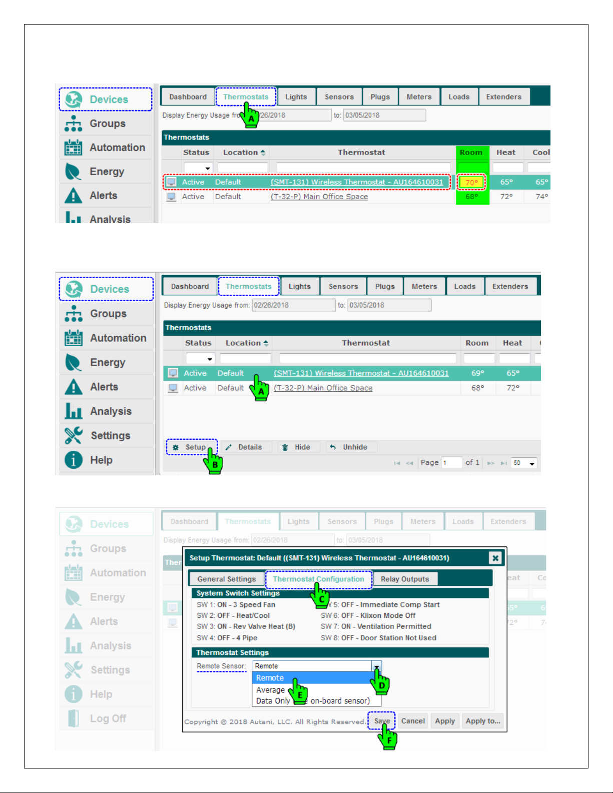
1. The temperature readings from the sensors are averaged, which can be verified against the thermostat value. Click
on the Thermostat tab and verify the average temperature displayed in the respective thermostat.
2. If the EnOcean Bridge is connected to a SMT-131 Thermostat, the remote sensor inside the Thermostat
Configuration is set to Data Only (use on-board sensors) by default. This need to be changed to Remote Sensor.
3. Select the SMT-131 Thermostat from the list of thermostats, and click the Setup button.
4. The Setup Thermostat pop-up menu appears. Click the Thermostat Configuration tab and set Remote Sensor to
Remote.
Page | 20
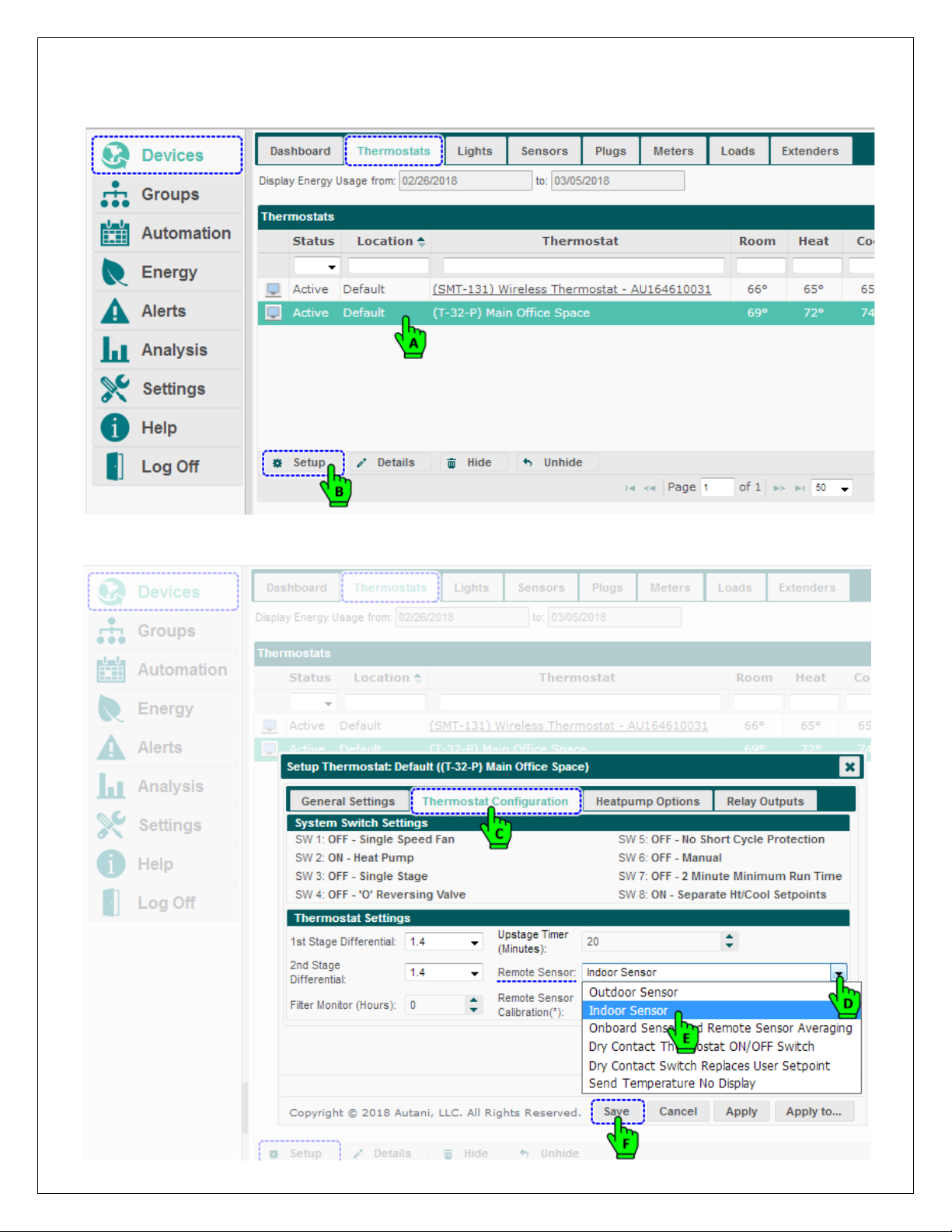
5. If the EnOcean Bridge is connected to a T-32-P Thermostat, the remote sensor inside the Thermostat Configuration
is set to Indoor Sensor by default. If it is not, change it to Indoor Sensor.
6. Select the T-32-P Thermostat from the list of thermostats, and click the Setup button.
7. The Setup Thermostat pop-up menu appears. Click the Thermostat Configuration tab and set Remote Sensor to
Indoor Sensor from the drop-down list. Click Save.
Table of contents


