AUTIC APPC-8429T User manual

Autic System Marine PC Rev. 1.3 Jan 2017
AUTIC SYSTEM MARINE PC
INSTALLATION AND USER MANUAL
Autic System Marine PC Rev. 1.1 Page 2
Disclaimer
Only qualified personnel can take care of installing and repairing these products. Autic System AS does not take
responsibility for products where the seal is broken by the customer. Claims for errors or omissions with the
item must be carried out without undue delay. Autic System AS liability is limited to repair or replacement of
the products. Autic System AS is not responsible for replacement costs or other consequential damages.
Trademarks
Windows XP, Windows 7 and Windows 10 are registered trademarks of Microsoft Corporation.
Intel®™ Bay Trail and Intel® Gen7 Intel® Graphics DX 11 are registered trademarks of Intel Corporation.
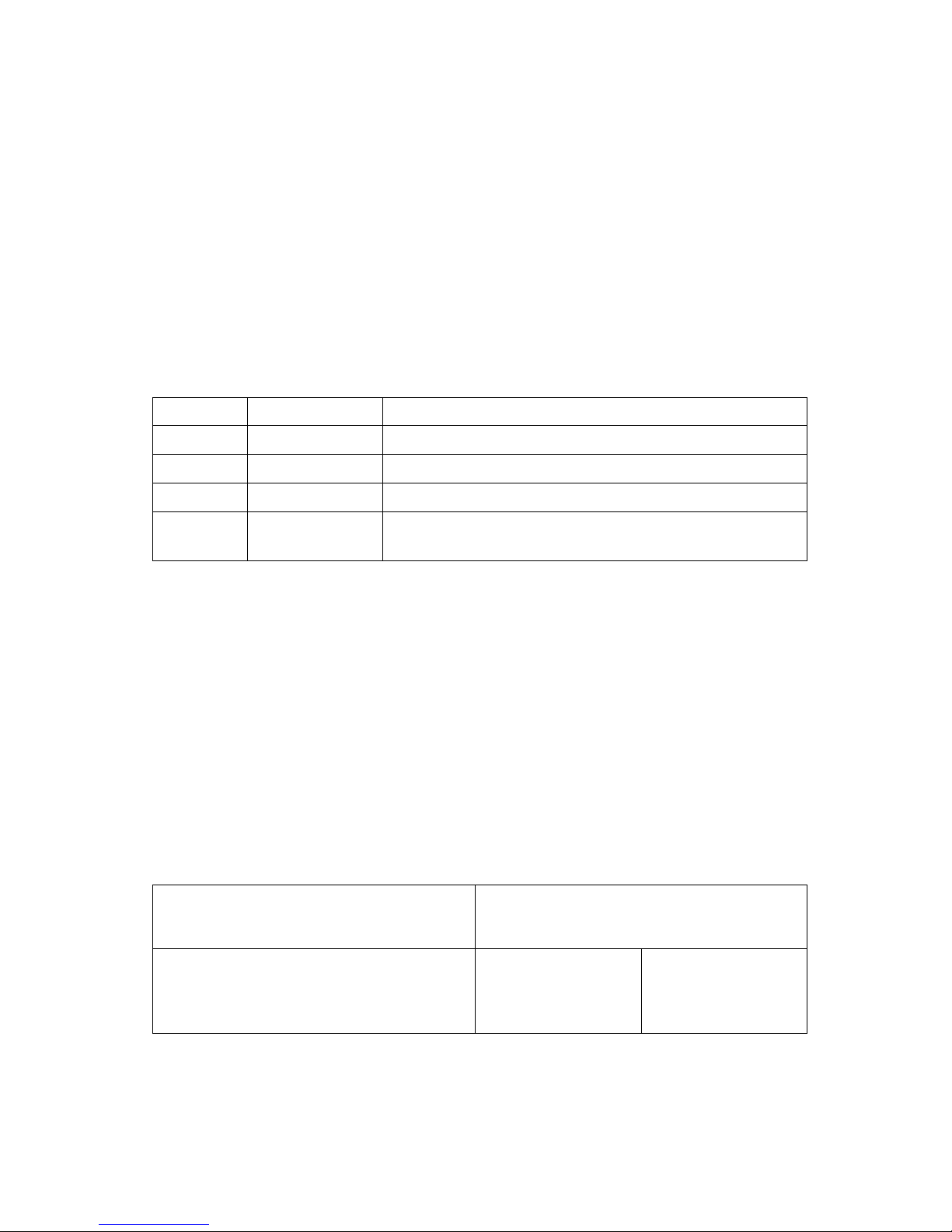
Revisions
Rev. No.
Date
Description
Rev. 1.0
June 2016
Draft
Rev. 1.1
26. Aug 2016
Final version
Rev. 1.2
28. Nov 2016
Added more detailed description of dimming buttons
Rev. 1.3
30. Jan 2017
Updated info regarding changed default settings of COM port
(+5VDC on PIN 9: disabled)
Addresses
Postal address:
Box 2099, 3103 Tønsberg, Norway
Visiting address:
Stoltenbergsgate 48, 3110 Tønsberg, Norway
Telephone:
+47 33 30 09 50
Telefax:
+47 33 30 09 55

Autic System Marine PC Rev. 1.1 Page 3
CONTENTS
Contents........................................................................................................................................................... 3
About the Autic Marine PC Product Series ....................................................................................................... 6
Autic Panel PC .................................................................................................................................................. 6
Range of Panel PC products ................................................................................................................................ 7
Product Identification.......................................................................................................................................... 7
Specifications Panel PC........................................................................................................................................ 8
Technical Data................................................................................................................................................. 8
Supported Operating Systems ........................................................................................................................ 8
Motherboard Specification ............................................................................................................................. 9
Panel PC Connectors.......................................................................................................................................... 11
I/O Panel ....................................................................................................................................................... 12
COM Ports ..................................................................................................................................................... 12
Ethernet ........................................................................................................................................................ 13
USB................................................................................................................................................................ 13
Installing the Panel PC....................................................................................................................................... 14
Package contents .......................................................................................................................................... 14
Mechanical Installation ................................................................................................................................. 14
Compass Safety Distance .............................................................................................................................. 14
Installation Methods ..................................................................................................................................... 15
Electrical Installation..................................................................................................................................... 16
Verification.................................................................................................................................................... 16
Using the Panel PC ............................................................................................................................................ 17
On-Off and Reset Buttons ............................................................................................................................. 17
Remote On-Off Switch .................................................................................................................................. 17
Restore on AC/Power Loss............................................................................................................................ 17
Monitor Adjustment, models with High brightness...................................................................................... 18
Autic Box PC................................................................................................................................................... 19
Range of Box PC products ................................................................................................................................. 20
Product Identification........................................................................................................................................ 20
Specifications Box/Mini PC................................................................................................................................ 20
Technical Data............................................................................................................................................... 21
Supported Operating Systems ...................................................................................................................... 21
Motherboard Specification ........................................................................................................................... 22
Box PC Connectors............................................................................................................................................. 24
I/O Panel ....................................................................................................................................................... 25
COM Ports ..................................................................................................................................................... 25
Ethernet ........................................................................................................................................................ 26
USB................................................................................................................................................................ 26
Installing the Box/Mini PC ................................................................................................................................. 27
Package contents .......................................................................................................................................... 27

Autic System Marine PC Rev. 1.1 Page 4
Mechanical Installation ................................................................................................................................. 27
Compass Safety Distance .............................................................................................................................. 27
Installation Options....................................................................................................................................... 27
Electrical Installation..................................................................................................................................... 28
Verification.................................................................................................................................................... 28
Using the Box/Mini PC....................................................................................................................................... 29
On-Off and Reset Buttons ............................................................................................................................. 29
Remote On-Off Switch .................................................................................................................................. 29
Restore on AC/Power Loss............................................................................................................................ 29
Autic Marine Monitors................................................................................................................................... 30
Range of Products ............................................................................................................................................. 31
Product Identification........................................................................................................................................ 31
Specification Monitors ...................................................................................................................................... 32
Technical Data............................................................................................................................................... 32
Monitor Connectors .......................................................................................................................................... 33
Installing the Monitor ....................................................................................................................................... 34
Package Contents.......................................................................................................................................... 34
Mechanical Installation ................................................................................................................................. 34
Compass Safety Distance .............................................................................................................................. 34
Installation methods ..................................................................................................................................... 35
Electrical Installation..................................................................................................................................... 36
Verification.................................................................................................................................................... 36
Using the Monitor ............................................................................................................................................. 37
Monitor Adjustments.................................................................................................................................... 37
Monitor Adjustments (old version)............................................................................................................... 38
Product Dimensions ....................................................................................................................................... 39
Panel PC Dimensions ......................................................................................................................................... 39
Panel PC 4:3 models...................................................................................................................................... 40
Panel PC 16:9 models.................................................................................................................................... 43
Box/Mini PC Dimension ..................................................................................................................................... 45
Monitor Dimensions .......................................................................................................................................... 46
UEFI and BIOS Settings ................................................................................................................................... 47
Introduction....................................................................................................................................................... 47
UEFI Menu Bar .............................................................................................................................................. 47
Navigation Keys............................................................................................................................................. 48
Main Screen....................................................................................................................................................... 48
Advanced Screen ............................................................................................................................................... 49
Instant Flash .................................................................................................................................................. 49
CPU Configuration......................................................................................................................................... 50
Chipset Coniguration..................................................................................................................................... 51
Storage Configuration ................................................................................................................................... 52

Autic System Marine PC Rev. 1.1 Page 5
Intel® Smart Connect Technology ................................................................................................................. 53
Super IO Configuration.................................................................................................................................. 53
ACPI Configuration ........................................................................................................................................ 54
USB Coniguration .......................................................................................................................................... 55
Hardware Health Event Monitoring Screen ...................................................................................................... 55
CPU_FAN1 Setting......................................................................................................................................... 55
CHA_FAN1 Setting......................................................................................................................................... 56
Case Open Feature........................................................................................................................................ 56
Clear Status ................................................................................................................................................... 56
Security Screen .................................................................................................................................................. 56
Supervisor Password ..................................................................................................................................... 56
User Password............................................................................................................................................... 56
Secure Boot................................................................................................................................................... 56
Boot Screen ....................................................................................................................................................... 57
Fast Boot ....................................................................................................................................................... 57
Boot From Onboard LAN............................................................................................................................... 57
Setup Prompt Timeout.................................................................................................................................. 57
Bootup Num-Lock ......................................................................................................................................... 57
Boot Beep...................................................................................................................................................... 57
Full Screen Logo ............................................................................................................................................ 57
CSM (Compatibility Support Module) ........................................................................................................... 58
Exit Screen ......................................................................................................................................................... 58
Save Changes and Exit................................................................................................................................... 58
Discard Changes and Exit .............................................................................................................................. 58
Discard Changes ............................................................................................................................................ 58
Load UEFI Defaults ........................................................................................................................................ 58
Launch EFI Shell from filesystem device ....................................................................................................... 59
Operating System........................................................................................................................................... 59
Customer Specified or Trial Version .................................................................................................................. 59
Shutting Down Properly .................................................................................................................................... 59
Declaration of Conformity for LCD Display ..................................................................................................... 60
Service ........................................................................................................................................................... 61
Return of products to Autic System................................................................................................................... 61
Accessories ........................................................................................................................................................ 62

Autic System Marine PC Rev. 1.1 Page 6
ABOUT THE AUTIC MARINE PC PRODUCT SERIES
Autic System provides a series of Panel PCs, Box/Mini PC and Monitors approved for use in industrial and
marine applications. All products are designed for operation without any moving parts, like ventilation fan and
mechanical hard disk drive. We offer Panel PCs with all functions included or Box/Mini PC with external
monitor(s). All parts are based on the same base of hardware. DNV GL 2.4 and IEC 60945 approve the products
for Marine usage.
1. Touch-screen Panel PCs with screen sizes from 8,4” to 24”
2. Box PC with identical Motherboard as the Panel PC series.
3. Touch-screen Monitor’s with screen sizes from 8,4” to 24”
This manual covers the Panel PC, Box/Mini PC and Monitors.
AUTIC PANEL PC
The APPC series is Panel PCs designed for Autic System for optimal solution of HMI functionality to marine and
industrial markets. Fanless design with solid aluminium front bezel. Powerful CPU based on Intel Bay Trail
N2930 quad Core processor provides maximum performance based on known platform. Intel® Gen7 Intel®
Graphics processor for quick screen refresh. The PC provides practical functionality such as easy access to the
hard drive and connectors for redundant power supplies.
Front bezel
Membrane keypad for monitor
adjustment
Touch screen
IO and power connectors
Autic System Marine PC Rev. 1.1 Page 7
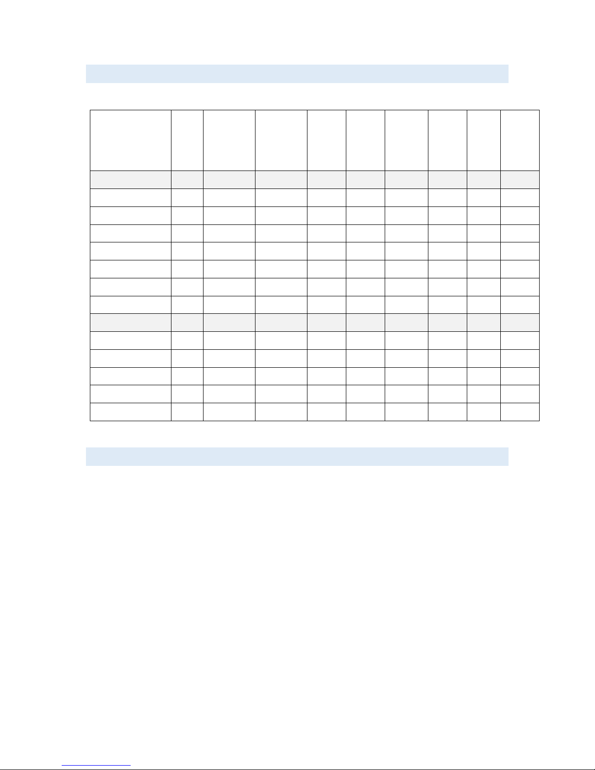
RANGE OF PANEL PC PRODUCTS
DNV GL 2.4 and IEC60945 approved.
Screen
size
Screen
resolution
Display
brightness
Colours
RS-232
RS-485
RS-422
Additiona
l RS-232
ports
USB
(2.0)
USB
(3.0)
PCIe x1
slot
Power
consum
ption
Display format 4:3
APPC-8429T
8.4”
800x600
450 nit LED
262K
3
0
2+ 2
0
30 W
APPC-1029T
9.6”
800x600
300 nit CCFL
262K
3
0
4 + 2
0
30 W
APPC-10429T-XG
10.4”
1024x768
300 nit LED
262K
3
0
4 + 2
0
30 W
APPC-1229T-XG
12”
1024x768
420 nit LED
16.7M
3
2
4 + 2
0
30 W
APPC-1529T
15”
1024x768
250 nit LED
16.7M
3
0
4 + 2
1
50 W
APPC-1729T
17”
1280x1024
250 nit LED
16.7M
3
0
4 + 2
1
40 W
APPC-1929T
19”
1280x1024
300 nit LED
16,7M
3
1
4 + 2
1
40 W
Display format 16:9
APPC-11629T
11,6”
1366x768
250 nit LED
262K
3
2
4 + 2
0
30 W
APPC-15629T
15,6”
1920x1080
300 nit LED
262K
3
0
4 + 2
1
40 W
APPC-18529T
18,5”
1920x1080
300 nit LED
16.7M
3
1
4 + 2
1
50 W
APPC-2229T
22”
1920x1080
300 nit LED
16.7M
3
1
4 + 2
1
60 W
APPC-2429T
24”
1920x1080
300 nit LED
16.7M
3
2
4 + 2
1
70 W
PRODUCT IDENTIFICATION
Product description: APPC-2429T-MK-8N
APPC Product family name (Autic Panel PC)
24 Size of display
29 Motherboard Id. (Intel 2930)
TTouch screen
MK Membrane keypad for monitor adjustment. Located at the front bezel.
8N/10N Sun readable. LED backlight (800 / 1000 nit)
Serial number: 1929T-AMK-10N-DC-SSD120G-1604022-C
TTouch Screen
AMK Aluminium bezel with membrane keypad
10N Display brightness. 10N=10 nits, 8N=8 nits, 5N= 5 nits
DC DC power supply built-in
SSD120G120GB SSD
1604022 16 = 2016; 04 = April, 022 = 22th unit of this batch
CMechanical version C

Autic System Marine PC Rev. 1.1 Page 8
SPECIFICATIONS PANEL PC
All models are as standard fitted with 4 GB of RAM, 2 Gb LAN ports, PCIe x1 slot*, RS-232/422/485 ports*,
resistive touch screen, 120GB SSD drive. Power supplied by 9 to 32 VDC. Adapter 100 –240 VAC to 12 VDC
included in the delivery. HDMI / VGA output for additional monitor.
*PCIe x1 slot and number of serial ports depend on the size of the Panel PC.
Optional equipment
- Membrane keypad in front for backlight dimming and display adjustment
- 2 LAN port (Total 4 ports)
- Sun readable monitor
- Up to 8GB RAM
- LPT printer port
- 2nd SDD/HDD
- Isolated PCIe- IO board for serial ports RS-422/485 and CAN bus. (DNV approved)
TECHNICAL DATA
Front panel protection
IP55
Rear panel protection
IP20
Power supply
+24 VDC (9-32 VDC).
Power adapter (Model according to
consumption)
100 –240 VAC to 12 VDC
Power consumption
30 to 80 W
Ambient temperature. Vertical mounting
0° to +60°C
Ambient temperature. Horizontal mounting
0° to +50°C
Storage temperature
-20°to+80°C
Relative humidity
5-85% non-condensing
Approvals
CE/ FCC/Rohs
Marine certification
DNV 2.4 and IEC60945
SUPPORTED OPERATING SYSTEMS
The CPU supports Windows 7, 8 and 10 operating system. Linux Kubuntu. Ask for other Linux versions.
It does not support Windows XP.

Autic System Marine PC Rev. 1.1 Page 9
MOTHERBOARD SPECIFICATION
Form Factor
Dimensions
Mini-ITX (6.7-in x 6.7-in)
Processor System
CPU
Intel® TM Bay Trail-M/D Processor Supports Hyper-Threading
Technology
Core Number
4
Max Speed
2,16GHz
Cache
2MB
Chipset
N/A
BIOS
UEFI
Expansion Slot
PCI
0
Mini-PCIe
1 (Half Size)
mSATA
1
PCIe
1 (x1 slot)
CFast Card
Socket
0
Memory
Technology
Dual Channel DDR3L 1333 MHz SDRAM
Max.
8GB
Socket
2 x SO-DIMM
Graphics
Controller
Intel® Gen7 Intel® Graphics DX 11, OGL3.2
VRAM
Shared Memory
VGA
Supports max. resolution 1920x1200
LVDS
Dual Channel 24-bit, max resolution
1920x1200@60Hz
HDMI
Supports HDMI 1.4a, max resolution 1920x1200
DVI
No
DisplayPort
No
Multi Display
Yes (Dual Display)
Ethernet
Ethernet
10/100/1000 Mbps
Controller
GbE LAN: 2 x Realtek RTL8111G-CG
Connector
2 x RJ-45
SATA
Max Data
Transfer
Rate
SATA2 (3.0Gb/s)
Rear I/O
VGA
1
DVI
0
HDMI
1
DisplayPort
0
Ethernet
2
USB
4 (2 x USB 3.0, 2 x USB 2.0)
Audio
2 (Mic-in, Line-out)
Serial
3 (RS232/422/485)
PS/2
2 (1 x keyboard, 1 x mouse)

Autic System Marine PC Rev. 1.1 Page 10
Internal Connectors
USB
6 (2 x USB 3.0, 4 x USB 2.0)
LVDS/Inverter
1/1
VGA
0
Serial
2 (RS232)
SATA
2 x SATA2(3.0Gb/s)
mPCIe
1
Parallel (LPT)
1
mSATA
1(shared)
IrDA
0
GPIO
8-bit 4 x GPI + 4 x GPO
SATA PWR
Output Con
1
Speaker
Header
1
Watchdog Timer
Output
Output from super I/O to drag RESETCON#
Interval
256 Segments, 0,1,2…255 Sec/Min
Power Requirements
Input
PWR 9-19V DC-In (4-pin ATX PWR Con)
Power On
AT/ATX Supported
-AT : Directly PWR on as power input ready
-ATX : Press button to PWR on after power input ready
Environment
Temperature
0ºC –60ºC
Autic System Marine PC Rev. 1.1 Page 11
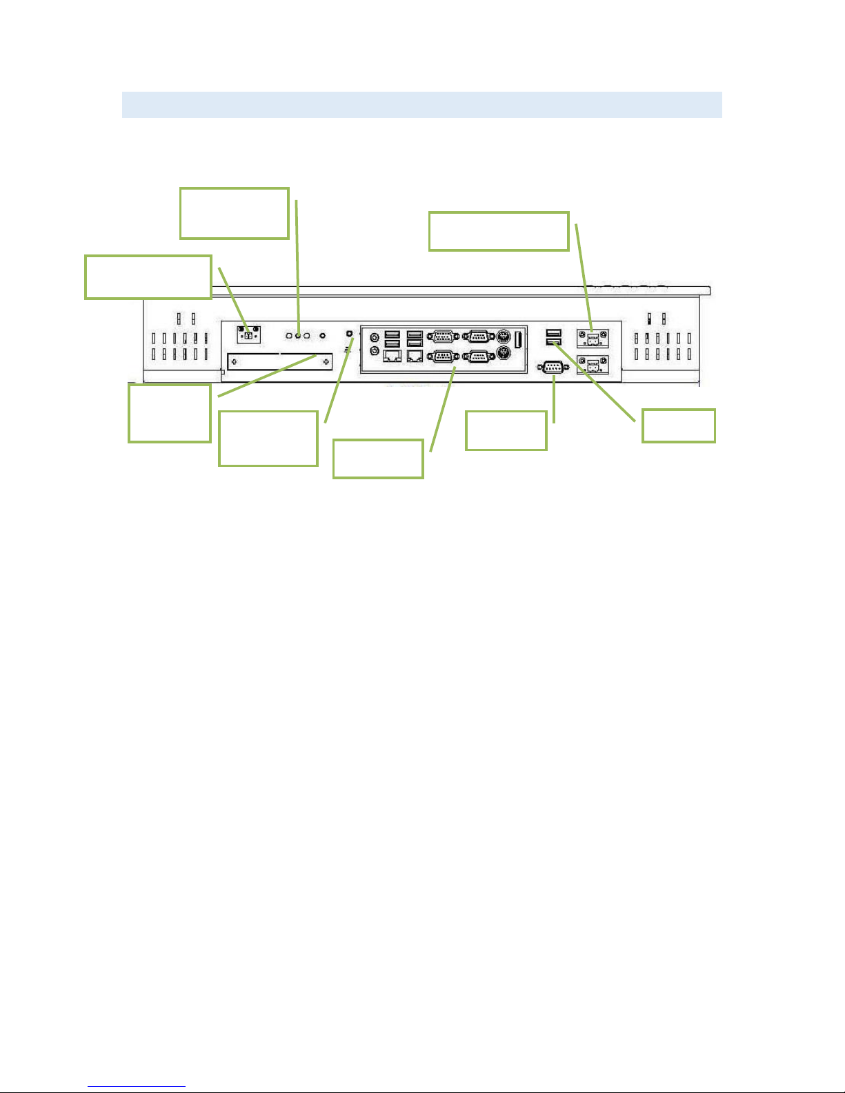
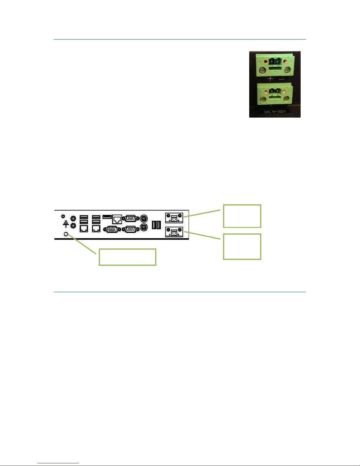
PANEL PC CONNECTORS
*The number of serial ports depend on the size of the Panel PC.
2xUSB
Dual 9-32VDC Power
ON/OFF and
Reset button
COM port*
Ground
terminal
PCIe x1
Slot
Remote ON/OFF
I/O Panel

Autic System Marine PC Rev. 1.1 Page 12
I/O PANEL
13 12 11 10 9 8
1: PS/2 Mouse Port
8: USB 3.0 Ports (USB3_0_1)
2: COM Port 1 (COM1)*
9: USB 2.0 Ports (USB_0_1)
3: COM Port 3 (COM3)*
10: VGA Port (VGA1)
4: LAN RJ-45 Port
11: COM Port 2 (COM2)*
5: LAN RJ-45 Port
12: PS/2 Keyboard Port
6: Line out (Green)
13: HDMI Port (HDMI1)
7: Microphone (Pink)
* This motherboard supports RS232/422/485 on COM ports 1~3. Please refer to below table for the pin
definition. In addition, COM1~3 ports (RS232/422/485) can be adjusted in BIOS setup utility > Advanced Screen
> Super IO Configuration
COM PORTS
COM1-3 D-sub 9-Pin RS-232/485/422
PIN
RS232
RS422
RS485
1
DCD
TX-
RTX-
2
RXD
RX+
N/A
3
TXD
TX+
RTX+
4
DTR
RX-
N/A
5
GND
GND
GND
6
DSR
N/A
N/A
7
RTS
N/A
N/A
8
CTS
N/A
N/A
9
COM1:
+5V/+12V/+5VSB
COM2, 3: +5V/+12V
COM1:
+5V/+12V/+5VSB
COM2, 3: +5V/+12V
COM1:
+5V/+12V/+5VSB
COM2, 3: +5V/+12V
When setting COM 1~3 to RS-485 in BIOS, also enable Auto Flow Control if applicable.
6
1
2
4
3
5
7

Autic System Marine PC Rev. 1.1 Page 13
COM 4 and 6 D-sub 9-Pin RS-232
PIN
RS232
1
DCD
2
RXD
3
TXD
4
DTR
5
GND
6
DSR
7
RTS
8
CTS
9
COM1: +5V/+12V/+5VSB. COM2, 3: +5V/+12V
For units ordered up to and including 2016: The COM ports supplies
+5VDC by default, so it could cause reset of the computer if short
circuited (i.e. Pin 9 ↔ Shielding). Please do not plug/unplug COM ports
when PC is powered ON.
For units ordered in 2017 and later, +5VDC on Pin 9 is disabled by default.
ETHERNET
Activity LED status
Description
Activity LED
Speed LED
Speed LED status
Description
Off
No Link
Off
10Mbps
Blinking
Data Activity
Orange
100Mbps
On
Link
Green
1Gbps
USB
USB Pin Configuration
The Panel PC has galvanic isolation against the 24 VDC feed. There is no galvanic isolation between the
communication ports for RS-232, RS-422/485 and USB.
Autic System Marine PC Rev. 1.1 Page 14
INSTALLING THE PANEL PC
PACKAGE CONTENTS
The Panel PC is shipped in customized dual layer cardboard packaging with polystyrene protection.
Standard delivery:
Panel PC
Power cable with connector
Power adapter 100 –240 VAC to 12 VDC
Gasket for panel mounting
Quick mounting kit
CD with drivers
When specified, Operating System Recovery DVD
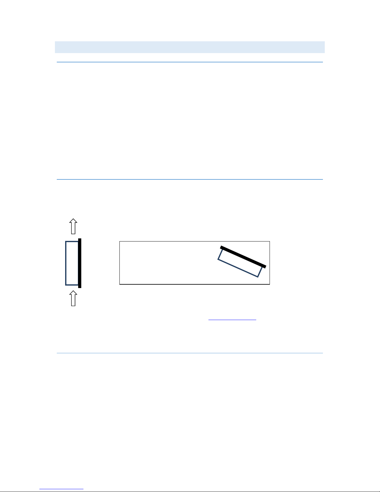
MECHANICAL INSTALLATION
Panel PC should be installed in vertical position to prevent overheating.
For product and cutout dimensions, please refer to the chapter Product Dimensions. Make the cutout
according cutout dimension for the selected model.
COMPASS SAFETY DISTANCE
The Panel PC is certified according to DNV 2.4 and IEC60945 for bridge installation.
Standard compass safe distance: 95 cm
Steering compass safe distance: 65 cm
Air flow
IMPORTANT!
For installation at an angle, the PC
must be equipped with a ventilation
fan.

Autic System Marine PC Rev. 1.1 Page 15
INSTALLATION METHODS
There are four methods for installation. Quick mounting is standard.
Quick mounting fittings.
10 screws with nuts behind front bezel.
4 screws through holes in the front bezel (OPTIONAL). Suitable when there is no access from rear.
Prepared for VESA standard bracket at rear side.
Various sizes according to size of Panel PC.
Fastening holes in monitor back plate.
Autic System Marine PC Rev. 1.1 Page 16
ELECTRICAL INSTALLATION
The Panel PC is certified for the connection to grounded power supply according to
EN60950. The panel PC’s shall be supplied by the standard power adapter or by
another galvanically isolated supply of approved type.
There are two power connectors allowing the use of two individual power sources
to obtain redundancy. One power connector can be used for single input. Operating
voltage is from 9 to 32 VDC. Be aware of the current consumption for wire
dimension when using low supply voltage. Total power consumption can be up to 80
W.
The power input has polarity protection if + and –should be interchanged during installation.
Data cables connected to the unit should to be of the shield type.
We recommend that the shield is connected to ground on both sides.
We recommend using min. 4 mm² grounding wire.
Isolate PCB ground (0 V) from chassis ground (earth).
Signal ground (0 V) is isolated from chassis ground.
NOTE! Make sure the power is off when connecting and disconnecting the connectors.
VERIFICATION
Please observe the following during installation and startup.
1) Be accurate when mounting the gasket tape between the front bezel and the panel.
2) Cover the ventilation holes with a piece of paper to prevent metal shavings from entering the unit.
Remove again after installation to ensure sufficient ventilation.
3) Ground the unit according to installation instruction.
4) Make sure the polarity is correct for power connection before connecting to power outlet.
5) Keep signal cable and high voltage cable separated.
6) After power on, make sure that the system performs a normal startup of the OS.
7) The system may be delivered with a 30 day trial version of Windows OS. Make sure you have a valid
OS.
9-32VDC
Power
9-32VDC
Power
Ground
Autic System Marine PC Rev. 1.1 Page 17
USING THE PANEL PC
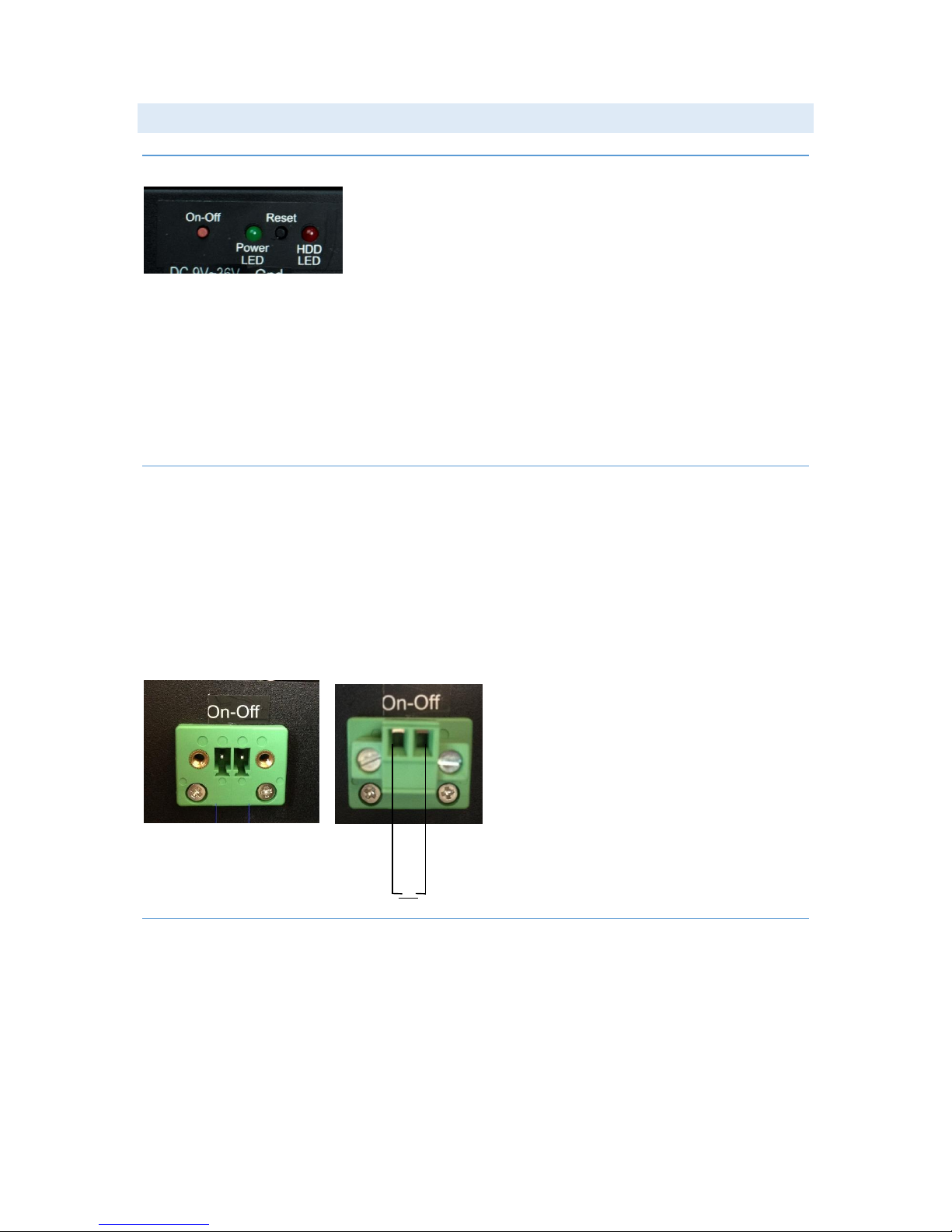
ON-OFF AND RESET BUTTONS
The On-Off button is at the rear side of the Panel PC. This button shuts down the system in a proper way. We
strongly recommend to first shut down the system via application software or operating system.
IMPORTANT!
Do not use the Reset button for normal restart! This button makes a hard reset of the system, and may cause
abnormal behavior for the operating system.
REMOTE ON-OFF SWITCH
Remote button/switch can control on-off operation of the Box PC. Attach a potential free Switch or relay for
operation.
Toggle function.
When Panel PC is off. Single touch/pulse will start the unit.
When Panel PC is on. Single touch/pulse will stop the unit.
RESTORE ON AC/POWER LOSS
The Restore on AC/Power loss is hard coded to “Power On”. Regardless of the value set in BIOS, the PC powers
on when the AC/power is restored.
Autic System Marine PC Rev. 1.1 Page 18
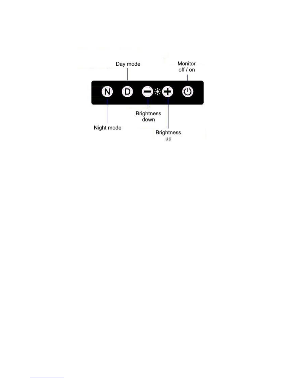
MONITOR ADJUSTMENT, MODELS WITH HIGH BRIGHTNESS
Membrane keypad for Panel PC with High Brightness display (Sun readable, 10N or 8N option)
For bridge solutions with dimming according to IEC 62288, the “Sun Readable”option have to be selected. For
operation in other locations on the ship, standard screen brightness is suitable.
Note:
1. The monitor off/on button does not switch off the touch functionality.
2. The + or –buttons may appear to react slowly. Try holding the button pressed in for about 3-5 seconds
to adjust the brightness. This is due to the number of dimming levels.
3. For models with a serial number prior to 1608004-A (manufactured before Aug 2016):
- After pushing Fully Dark, use Night Mode, Day Mode or + to bring light back.
Autic System Marine PC Rev. 1.1 Page 19
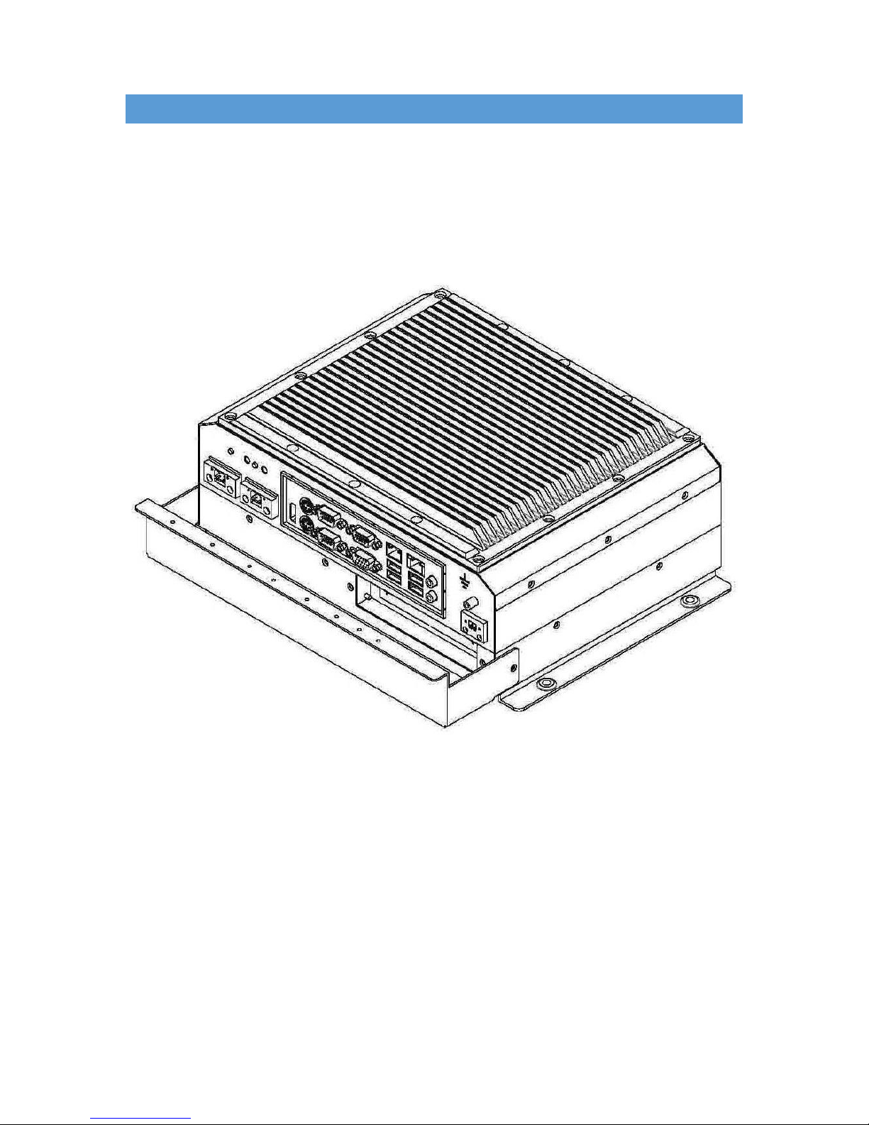
AUTIC BOX PC
The AMPC-2930 is a Box (or Mini) PC intended for marine and industrial use. A powerful CPU based on Intel Bay
Trail N2930 quad Core processor provides maximum performance based on known platform. Intel® Gen7 Intel®
Graphics DX 11 for quick screen refresh. The PC is delivered with practical functionality such as easy access to
the hard drive and redundant power supply connectors.

Autic System Marine PC Rev. 1.1 Page 20
RANGE OF BOX PC PRODUCTS
DNV GL 2.4 and IEC60945 approved.
LAN
RS-232-
C
RS-232,
RS-485,
RS-422
USB
(2.0)
(3.0)
Internal
Mini PCIe
Connector
PCIe
x1
slot
Power
consumption
AMPC-2930
2
2
3
4 + 2
1
1
25 W
The number of LAN and serial ports can be increased on request.
PRODUCT IDENTIFICATION
Product description: AMPC-2930
AMPC Product family name (Autic Mini PC)
2930 Motherboard Id. (Intel 2930)
Serial number: A2930-SSD120G-HS-DC-1604022-A
SSD120G 120GB SSD
HS Heat sink
DC DC power supply built-in
1604022 16 = 2016, 04 = April, 022 = 22th unit of this batch
A Mechanical version A
SPECIFICATIONS BOX/MINI PC
The mini/box PC is fitted with 4 GB of RAM, 2 Gb LAN ports, PCIe x1 slot*, RS-232/422/485 ports*, 120GB SSD
drive. Power supplied by 9 to 32 VDC. Adapter 100 –240 VAC to 12 VDC included in the delivery. HDMI / VGA
output for dual monitors.
Optional equipment
- 2 LAN port (Total 4 ports)
- Up to 8GB RAM
- LPT printer port
- 2nd SDD/HDD
- Isolated PCIe- IO board for serial ports RS-422/485 and CAN bus. (DNV approved)
This manual suits for next models
11
Table of contents
Popular Marine Equipment manuals by other brands


System Sensor
System Sensor B200S Application guide

Protekt
Protekt AT 183 instruction manual

Risco
Risco WL S42 installation instructions

Simrad
Simrad ITI TRAWL SYSTEM - SERIAL DATA COMMUNICATION REV... instruction manual

MAVIMARE
MAVIMARE GM2-MRA01 Installation instructions and owner's manual

Garmin
Garmin GPSMAP 527 Guide Reference