manuals.online logo
Brands
  1. Home
  2. •
  3. Brands
  4. •
  5. Kohler
  6. •
  7. Marine Equipment
  8. •
  9. Kohler 6EKOD User manual

Kohler 6EKOD User manual

TT-1696 11/16
INSTALLATION INSTRUCTIONS
Original Issue Date: 11/16
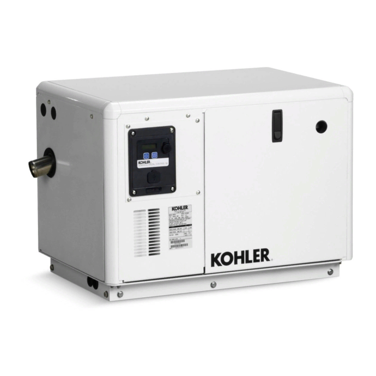
Model: 6EKOD/5EFKOD, 9EKOZD/7EFKOZD, and 11EKOZD/9EFKOZD Marine
Market: Marine with ADCIId Controller
Subject: Circuit Breaker Kit
Introduction
The AC circuit breakers protect the wiring from the
breakers to the vessel’s distribution panel. Install the
circuit breaker on the junction box side panel. Contact
an authorized distributor/dealer for application and
selection information.
Safety Precautions
Accidental starting.
Can cause severe injury or death.
Disconnect the battery cables before
working on the generator set.
Remove the negative (--) lead first
when disconnecting the battery.
Reconnect the negative (--) lead last
when reconnecting the battery.
WARNING
Disabling the generator set. Accidental starting can
cause severe injury or death. Before working on the
generator set or equipment connected to the set, disable the
generator set as follows: (1) Press the generator set off/reset
button to shut down the generator set. (2) Disconnect the
power to the battery charger, if equipped. (3) Remove the
battery cables, negative (--) lead first. Reconnect the negative
(--) lead last when reconnecting the battery. Follow these
precautions to prevent the starting of the generator set by the
remote start/stop switch.
Hazardous voltage.
Can cause severe injury or death.
Operate the generator set only when
all guards and electrical enclosures
areinplace.
Moving parts.
WARNING
Grounding electrical equipment. Hazardous voltage can
cause severe injury or death. Electrocution is possible
whenever electricity is present. Ensure you comply with all
applicable codes and standards. Electrically ground the
generator set, transfer switch, and related equipment and
electrical circuits. Turn off the main circuit breakers of all
power sources before servicing the equipment. Never contact
electrical leads or appliances when standing in water or on wet
ground because these conditions increase the risk of
electrocution.
Short circuits. Hazardous voltage/current can cause
severe injury or death. Short circuits can cause bodily injury
and/or equipment damage.Do not contact electrical
connections with tools or jewelry while making adjustments or
repairs. Remove all jewelry before servicing the equipment.
2TT-1696 11/16
Installation
Note: Read all safety precautions at the beginning of
this publication before performing any work on
the generator set.
1. Remove the generator set from service.
1.1 Press the generator set OFF/RESET button to
shut down the generator set
1.2 Disconnect the generator set engine starting
battery, the negative (--) lead first.
2. Install the circuit breaker.
2.1 Remove the screws from the right side junction
box panel and remove the panel.
2.2 Install the circuit breaker on the right side of the
junction box. Position the ON side of the circuit
breaker toward the rear of the junction box.
2.3 Single Pole Circuit Breaker Attach the stator
lead marked 1 to the side of the circuit breaker
marked LINE (see Figure 1). Bolt together leads 2
and 3 and tape to insulate them from ground.
Attach the stator lead marked 4 to L0. Attach the
customer load lead connection to the LOAD side
of the circuit breaker.
Two Pole Circuit Breaker Attach the stator leads
(1 and 2) to the LINE side of the circuit breaker and
attach the customer load lead connection to the
LOAD side of the circuit breaker (see Figure 2).
Attach the stator leads marked 3 and 4 to LO.
Three Pole Circuit Breaker Attach the stator
leads (1, 2, and 3) to the LINE side of the circuit
breaker and attach the customer load lead
connection to the LOAD side of the circuit breaker
(see Figure 3). Attach the stator lead marked 4 to
LO.
Note: The neutral (L0) connection is located in
the junction box. See Figure 4.
2.4 If the kit includes cover plate(s) (229183), use the
cover plate(s) to cover any opening. See Figure 7.
3. Restore the generator set to service.
3.1 Check that the generator set is OFF.
3.2 Reconnect the generator set engine starting
battery, the negative (--) lead last.
Stator Leads
3412
L0 (NEU)
LINE
LOAD
Customer
Load Lead
Customer
Load Lead
1. Tape to insulate from ground
2. Circuit breaker, single pole
1
2
Figure 1 Single Pole Circuit Breaker Connections
Stator Leads
LINE
Customer
Load Lead
LOAD
Customer
Load Lead
L0 (NEU)
34 12
Figure 2 Double Pole Circuit Breaker Connections
TT-1696 11/16 3
Stator Leads
LINE
Customer
Load Lead
LOAD
Customer
Load Lead
L0 (NEU)
4321
Figure 3 Triple Pole Circuit Breaker Connections
1. L0 Connection
2. Ground connection
3. Junction box
1
2
3
GM76137-F
Figure 4 Neutral (L0) Connections
ADV-5875A-T
Figure 5 Generator Set Connections for units with
ADCIId Controller
Kit No.
Circuit
Breaker Amps. Poles
Max.
Voltage
GM77889-KP1 X-506-40 25 2250
GM77889-KP2 X-506-43 42 2250
GM77889-KP3 X-506-38 50 2250
GM77889-KP4 X-506-78 50 1250
GM77889-KP5 X-506-58 27 1250
GM77889-KP6 X-506-70 85 1250
GM77889-KP7 X-506-46 35 1250
GM77889-KP8 X-506-49 30 1250
GM77889-KP9 X-506-80 100 1250
GM77889-KP10 X-506-50 40 1250
GM77889-KP11 X-506-57 22 2250
GM77889-KP12 X-506-42 35 2250
GM77889-KP13 X-506-63 18 3480
GM77889-KP14 X-506-67 35 3480
GM77889-KP15 X-506-81 40 3250
GM77889-KP16 X-506-64 23 3480
GM77889-KP17 X-506-10 20 3250
GM77889-KP18 X-506-40 25 2250
GM77889-KP19 X-506-43 42 2250
GM77889-KP20 X-506-38 50 2250
Figure 6 Circuit Breaker Selection/Ratings (Listed
Numerically by Kit Number)
4TT-1696 11/16
1. Plate, cover (229183), if equipped.
2. Breaker, circuit (See Figure 6)
3. Teminal, jumper (249956), if equipped.
1 2
3
GM77889-B
USE EXISTING
HARDWARE
Figure 7 Circuit Breaker Assembly Drawing
Parts List
Qty. Description Part Number
Kits:GM77889-KP1/-KP2/-KP3/-KP11/-KP12
1Circuit breaker SeeFigure6
1Plate, cover 229183
Kits:GM77889-KP4/-KP5/-KP6/-KP7/-KP8/-KP9/-KP10
1Circuit breaker SeeFigure6
2Plate, cover 229183
Kits: GM77889-KP13/-KP14/-KP15/-KP16/-KP17
1Circuit breaker SeeFigure6
Kits: GM77889-KP18/-KP19/-KP20
1Circuit breaker SeeFigure6
1Plate, cover 229183
1Terminal, jumper 249956
KOHLER CO., Kohler, Wisconsin 53044 USA
Phone 920-457-4441, Fax 920-459-1646
For the nearest sales and service outlet in the
US and Canada, phone 1-800-544-2444
KOHLERPower.com
Kohler Power Systems
Asia Pacific Headquarters
7 Jurong Pier Road
Singapore 619159
Phone (65) 6264-6422, Fax (65) 6264-6455
Availability is subject to change without notice. Kohler Co. reserves the
right to change the design or specifications without notice and without any
obligation or liability whatsoever. Contact your local Kohlerrgenerator
set distributor for availability.
2016 by Kohler Co. All rights reserved.

Other manuals for 6EKOD

4

This manual suits for next models

5

Other Kohler Marine Equipment manuals

Kohler 40EFOZDJ User manual

Kohler

Kohler 40EFOZDJ User manual

Kohler 6EKOD User manual

Kohler

Kohler 6EKOD User manual

Kohler K-9246 Assembly instructions

Kohler

Kohler K-9246 Assembly instructions

Kohler 4EOZ Assembly instructions

Kohler

Kohler 4EOZ Assembly instructions

Kohler 13EKOZD User manual

Kohler

Kohler 13EKOZD User manual

Kohler 40EFOZ User manual

Kohler

Kohler 40EFOZ User manual

Kohler GM89754-KP1 User manual

Kohler

Kohler GM89754-KP1 User manual

Kohler 150EOZDJ User manual

Kohler

Kohler 150EOZDJ User manual

Kohler GM89754-KP2 User manual

Kohler

Kohler GM89754-KP2 User manual

Kohler 5E/4EF User manual

Kohler

Kohler 5E/4EF User manual

Kohler 5EOZ User manual

Kohler

Kohler 5EOZ User manual

Kohler GM31994-KP1 User manual

Kohler

Kohler GM31994-KP1 User manual

Kohler 5ECD User manual

Kohler

Kohler 5ECD User manual

Kohler 6EOD Instruction Manual

Kohler

Kohler 6EOD Instruction Manual

Kohler GM93516-KP1 User manual

Kohler

Kohler GM93516-KP1 User manual

Popular Marine Equipment manuals by other brands

POWERWINCH 825 Operation manual

POWERWINCH

POWERWINCH 825 Operation manual

JRC JLN-628 brochure

JRC

JRC JLN-628 brochure

DIGITAL YACHT PilotLink2 Product handbook

DIGITAL YACHT

DIGITAL YACHT PilotLink2 Product handbook

Clarion CMS2 Owner's manual & installation manual

Clarion

Clarion CMS2 Owner's manual & installation manual

EBS M7000 installation manual

EBS

EBS M7000 installation manual

Kongsberg M3 Bathy installation manual

Kongsberg

Kongsberg M3 Bathy installation manual

NPK SCS-1002 operating manual

NPK

NPK SCS-1002 operating manual

Furuno FE-800 installation manual

Furuno

Furuno FE-800 installation manual

Harken 1561 instructions

Harken

Harken 1561 instructions

Simrad DD15 manual

Simrad

Simrad DD15 manual

Notifier FS-BSO Installation and maintenance instructions

Notifier

Notifier FS-BSO Installation and maintenance instructions

Raymarine ST40 Quick reference guide

Raymarine

Raymarine ST40 Quick reference guide

Raymarine Maxiview ST80 Owner's handbook

Raymarine

Raymarine Maxiview ST80 Owner's handbook

E2S E2XS112UL Instructions/service manual

E2S

E2S E2XS112UL Instructions/service manual

GUIDANCE MARINE 20- Series Installer's guide

GUIDANCE MARINE

GUIDANCE MARINE 20- Series Installer's guide

R2Sonic 2026 Operation manual

R2Sonic

R2Sonic 2026 Operation manual

COBHAM SAILOR 6000 installation manual

COBHAM

COBHAM SAILOR 6000 installation manual

Raymarine ST60 Tridata Owner's handbook

Raymarine

Raymarine ST60 Tridata Owner's handbook

manuals.online logo
manuals.online logoBrands
  • About & Mission
  • Contact us
  • Privacy Policy
  • Terms and Conditions

Copyright 2025 Manuals.Online. All Rights Reserved.