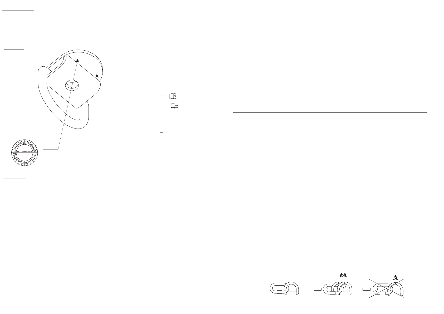
Fig.2. The marking
2
TIME OF USAGE
Anchor device can be used for 5 years . After this period device must be made a subject to detailed manufacturer's control.
The control can be carried out by:
- manufacturer
- or person recommended by manufacturer
- or company recommended by manufacturer.
During the control will be established time of usage till next fabric control.
MARKING
AT183
reference number
05/12
number
of manufacturing series
caution: read the manual
manufacturer
or distributor
load direction
European standard
EN795:2012 type A
Number person
1
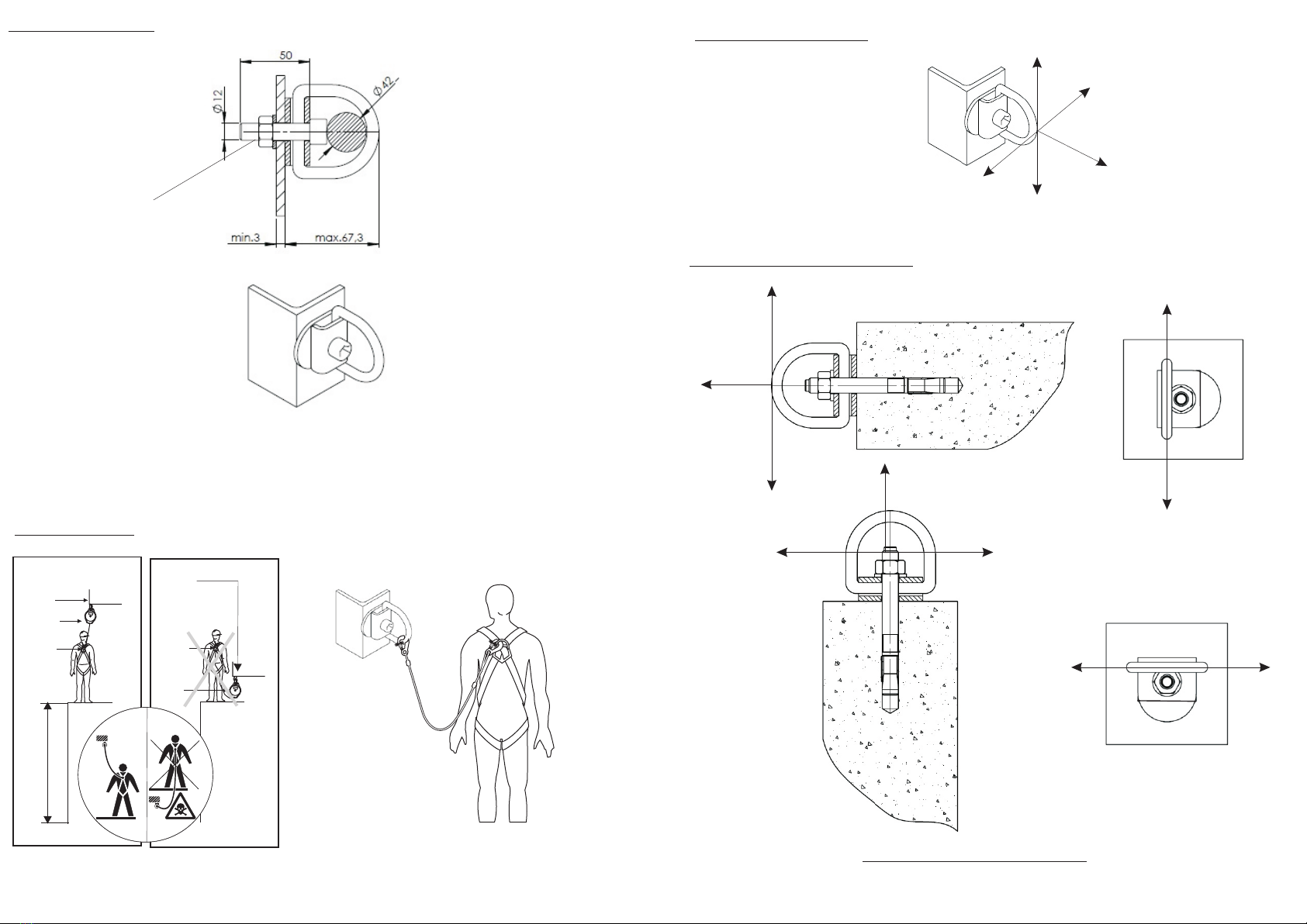
INSTALATION
Using the anchor point AT183 in connection with fall arrest system must be compatibile with use instructions of the fall arrest
systems and obligatory standards:
- EN 361 - for safety harness;
- EN 353-2, EN 355, EN 360 - for fall arrest equipment.
- EN 362 - for the connectors.
1. Before installing, the AT183 anchor point should be stored in a clean, dry place, in the conditions which prevent from
mechanical damage.
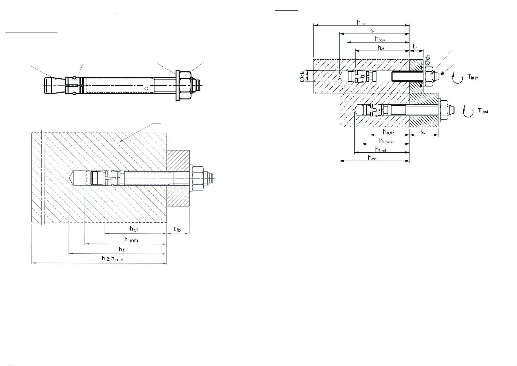
2. The installation of the anchor point must be conducted in accordance with the principles of making mechanical and
construction connections. For joining, use M12 screws for AT183 anchors , made of at least stainless steel class A2-70. Screw
length should be chosen according to the thickness of the elements combined.
3. Take into account the environmental conditions prevailing at the installation site, which might cause the corrosion of the
anchor point and connectors.
4.Please follow the instructions concerning the installation, contained in the information annex to the EN795 standard.
5.The connection to concrete substrate must be performed using mechanical anchors with the M12 threaded shank. The
concrete substrate should have a compressive strength of not less than 20MPa.
6.Installation examples are shown in the drawings.
7.Force transmitted to the structure is less than 12kN. For possible force directions see figure 3.
8. The deflection point does not exceed 5 mm.
9. Check clearance beneath the user!!!
BASIC PRINCIPLES OF USE
1. Before installing the anchor point,read this manual and strictly adhere to its recommendations.
2. This manual must always be available for the installer or operator of the anchor point.
3. The anchor point can be installed only by persons with appropriate knowledge and experience in this field, in particular the knowledge of the
EN795 standard, the knowledge of anchor installation in accordance with the guidelines of their manufacturers and the knowledge of this
manual. The installed anchor point must be checked (approved) by a person competent in this area (e.g. an engineer or a qualified designer),
who must also check the construction the building at the attachment point in terms of its strength.
4. The constructor of the anchor point is entirely responsible for its installation. Neither the manufacturer nor the distributor is responsible for careless or
inconsistent with the recommendations assembly. Upon request, the manufacturer and/or distributor provide all necessary technical information
concerning the product, its assembly technology, inspection and the product's declaration of conformity.
5. The personal protective equipment used with the anchor point must be attached using a connector compliant with EN362, taking into account the
recommendations contained in the instructions for use of this equipment.
6. AT183 must only be used for the attachment of personal protective equipment against falls from a height, in accordance with EN795 type A , in
such a way that the created protective system complies with EN363 standards.
7. In the case of the installation in materials other than those specified in this manual (e.g. in wood) the calculations checking the compliance of the
strength of the attachment with EN795 must be commissioned to a qualified designer.
8. It is forbidden to use the anchor point with apparent defects (corrosion, cracks, deformation).
9. It is forbidden to use the anchor point, which was involved in arresting a fall.
10. It is forbidden to attach more than one person.
11. Using the anchor point for hoisting loads is forbiden.
12. Unauthorized modifications of the device are forbidden.
13. During the installation, the protective system must be planned in such a manner that the anchor point is located above the user.
14. In the protection system limiting force of fall below < 6 kN has fo be used for example retractable fall arrester or lanyard with
energy absorber.
THE ESSENTIAL PRINCIPLES FOR USERS OF PERSONAL PROTECTIVE EQUIPMENT AGAINST FALLS FROM A HEIGHT
*personal protective equipment shall only be used by a person trained and competent in its safe use.
*personal protective equipment must not be used by a person with medical condition that could affect the safety of the equipment user in normal and
emergency use.
*a rescue plan shall be in place to deal with any emergencies that could arise during the work.
*it is forbidden to make any alterations or additions to the equipment without the manufacturer's prior written consent.
*any repair shall only be carried out by equipment manufacturer or his certified representative.
*personal protective equipment shall not be used outside its limitations, or for any purpose other than that for which it is intended.
*personal protective equipment should be a personal issue item.
*before use ensure about the compatibility of items of equipment assembled into a fall arrest system. Periodically check connecting and adjusting of the
equipment components to avoid accidental loosening or disconnecting of the components.
*it is forbidden to use combinations of items of equipment in which the safe function of any one item is affected by or interferes with the safe function of
another.
*before each use of personal protective equipment it is obligatory to carry out a pre-use check of the equipment, to ensure that it is in a serviceable
condition and operates correctly before it is used.
*during pre-use check it is necessary to inspect all elements of the equipment in respect of any damages, excessive wear, corrosion, abrasion, cutting or
incorrect acting, especially take into consideration:
- in full body harnesses and belts - buckles, adjusting elements, attaching points, webbings, seams, loops;
- in energy absorbers - attaching loops, webbing, seams, casing, connectors;
- in textile lanyards or lifelines or guidelines - rope, loops, thimbles, connectors, adjusting element, splices;
- in steel lanyards or lifelines or guidelines - cable, wires, clips, ferrules, loops, thimbles, connectors, adjusting elements;
- in retractable fall arresters - cable or webbing, retractor and brake proper acting, casing, energy absorber, connector;
- in guided type fall arresters - body of the fall arrester, sliding function, locking gear acting, rivets and screws, connector, energy absorber;
- in connectors - main body, rivets, gate, locking gear acting.
*after every12 months of utilization, personal protective equipment must be withdrawn from use to carry out periodical detailed inspection. The periodic
inspection must be carried out by
a competent person for periodic inspection. The periodic inspection can be carried out also by the manufacturer or his authorized representative.
*In case of some types of the complex equipment e.g. some types of retractable fall arresters the annual inspection can be carried out only by the
manufacturer or his authorized representative.
*regular periodic inspections are the essential for equipment maintenance and the safety of the users which depends upon the continued efficiency and
durability of the equipment.
*during periodic inspection it is necessary to check the legibility of the equipment marking.
*it is essential for the safety of the user that if the product is re-sold outside the original country of destination the reseller shall provide instructions for use,
for maintenance, for periodic examination and for repair in language of the country in which the product is to be used.
*personal protective equipment must be withdrawn from use immediately when any doubt arise about its condition for safe use and not used again until
confirmed in writing by equipment manufacturer or his representative after carried out the detailed inspection.
*personal protective equipment must be withdrawn from use immediately and destroyed when it have been used to arrest a fall
,
*a full body harness (conformed to EN 361) is the only acceptable body holding device that can be used in a fall arrest system.
*in full body harness use only attaching points marked with big letter "A" to attach a fall arrest system. Marking like "A/2'" or a half of "A" means the
necessity of attaching a fall arrest system to both attaching points together simultaneously. It is strictly forbidden to attach a fall arrest system to the
single attaching point marked "A/2'" or a half of "A". See drawings below:
A
FALL ARREST SYSTEM HARNESS ATTACHING POINT
AHARNESS ATTACHING HALF POINTS
FALL ARREST SYSTEM
FORBIDDEN!
month and year of the manufacturer's
next inspection
Don't use the device after this date
Attention: Before the first use
mark the date of the first inspection
(date of first use +12 months,
e.g. first use 01.2013 - mark inspection 01.2014)
2013
2014
8
3
E
1
T
N
A
7
9
5
t
:
2
0
1
2
t
y
p
e
A