Auto Spa Cover ASC-2 User manual
Installation Guide
Installation Guide for
Model# ASC-2
Patent# 7,461,415

ASC-2 (Patent# 7,461,415)
AUTO SPA COVER INSTRUCTION MANUAL
Document Number RE:ASC-2-E4
Auto Spa Cover Inc (ASC) has prepared this manual for use by authorized installation personnel. The informa-
tion contained herein is the property of ASC and shall not be reproduced in whole or in part without the prior
written approval of ASC.
ASC reserves the right to make changes without notice to the specication(s) and materials contained herein
and shall not be responsible for any damages (including consequential) caused by reliance on the materials
presented, including but not limited to typographical or listing errors.
Please address any questions, comments and suggestions to:
AUTO SPA COVER INC
Paso Robles, CA 93446
Tel: (805) 226-5030
www.autospacover.com
The ASC-2 is designed for spas 7ft or larger in length with 2 1/2” thick covers.
We offer kits for smaller spas and/or newer 4” thick spa covers.
Disclaimer:
The information contained in this Manual is for general information purposes only. The information is
provided by AutoSpaCover and while we endeavor to keep the information up to date and correct, we
make no representations of any kind, express or implied, about the completeness, accuracy, reliability,
suitability or availability with respect to the information, products, services, or related graphics con-
tained in this Manual for any purpose. Any reliance you place on such information is therefore strictly
at your own risk.
In no event will we be liable for any loss or damage including without limitation, indirect or consequential
loss or damage whatsoever arising from the use of this Manual.
AutoSpaCover is not responsible for water logged or overweight covers , ASC assumes no responsibility
for system failure due to water logged covers.
AutoSpaCover may not function properly with an over weight/water logged cover.
Spa/hot tub covers should not weigh more that 2 times the weight of a new dry cover.
DO NOT LET CHILDREN USE THE REMOTE CONTROL OR OPERATE THE ASC-2
January 12th, 2016
Legal Information

Table of Contents
ASC Installation Instructions
Diagram 4
Parts List 5
TURN OFF POWER TO SPA 6
Clearance chart 7
Installing Control Box 7
Connecting Power to Control Box 8
Locating the Motor mounting points 10
Routing the motor wires 11
Attaching Side Bar Assemblies to Spa 12
Wiring up Motors 13
Initial Motor Test 14
Installing the “C” clamps 15
Installing the Shoulder Bolt and Stop Bolt Assemblies 21
Attaching Cover to Side Bars 23
Finalizing Stop Bolt Positions 24
Installing the Backstops 25
Final Look 27
Maintenance 28
Assembly Guide for Side Bars and Motors 29
Troubleshooting 31
Parts List 32
Warranty 33
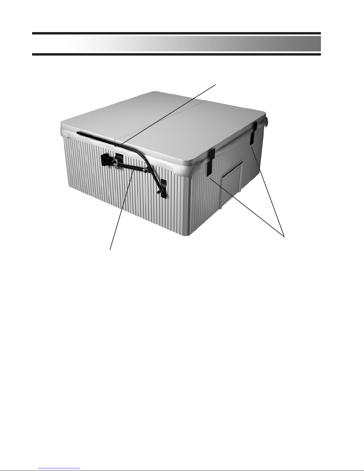
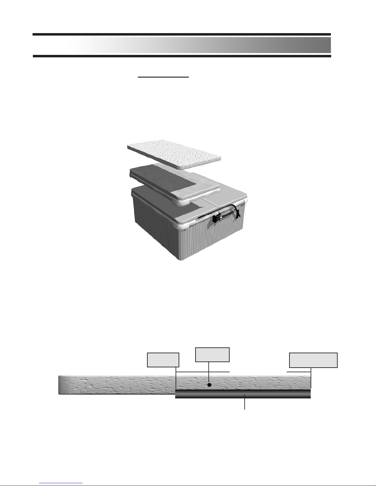
Diagram
Backstops (2)
Side Bar (2)
Motor Assembly (2)
1. Parts included in the kit
a. Electronics control assembly
b. Remote control receiver
c. Motor assembly ( 2 )
d. Backstops ( 2 )
e. Side Bars (2)
f. Assorted hardware w/ wire nuts and 2 sided tape
2. Tools needed
a. Phillips Screwdriver
b. Wrench - 1/2”, 7/16”, 3/4”, and 9/16” or 2 Crescent Wrenches
c. 3/4” Open End Wrench
d. Duct Tape
e. Power Drill
f. 1/4” drill bit
Time to install approximately 1-1/2 hour
REAR
FRONT
(4)
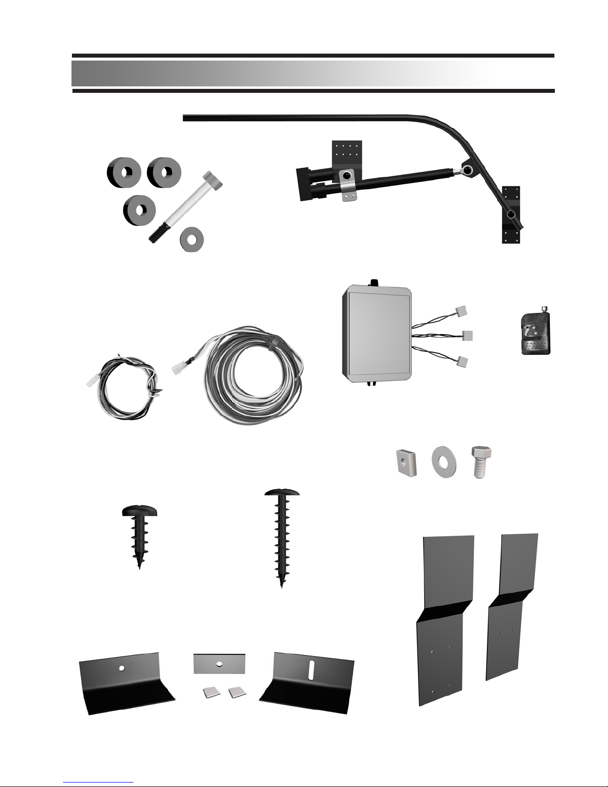
Parts List
(5)
ASC-2 Side bar Kit (2 sets)
Shoulder Bolt
Assembly (2 sets)
“C” Clamp kit (2 sets)
Stop Bolt Assembly (2 sets)
ASC-2 Control Box & Remote Control
ASC-2 Backstops (2)
Control Box
Mounting Screw (2) Wood Screws (40)
Motor & Power Wiring Harnesses

Installation
1a. Find the house electrical breaker box and
1b. Go to spa and make sure the power is off.
(ie: test lights, jets, etc)
IMPORTANT | IMPORTANT | IMPORTANT
IMPORTANT | IMPORTANT | IMPORTANT | IMPORTANT | IMPORTANT
IMPORTANT | IMPORTANT | IMPORTANT
IMPORTANT | IMPORTANT | IMPORTANT | IMPORTANT | IMPORTANT
TURN OFF
POWER TO SPA
(6)
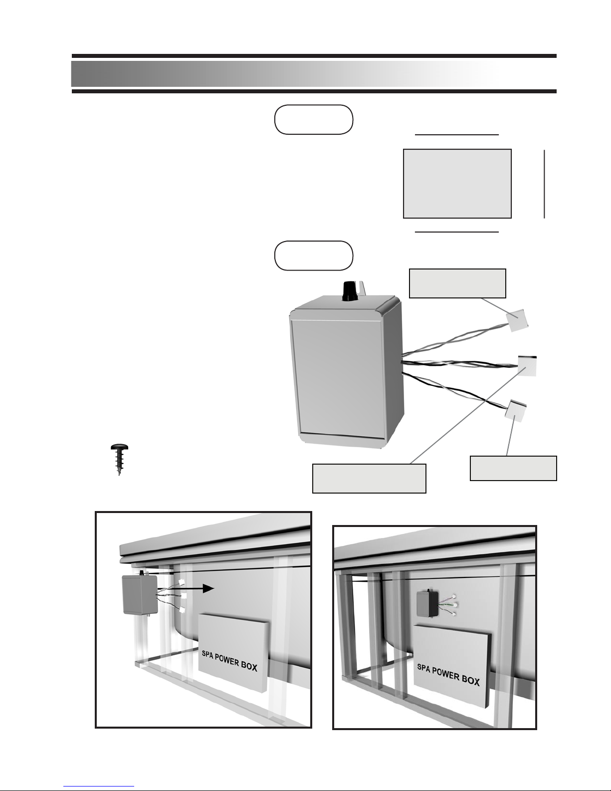
Installation
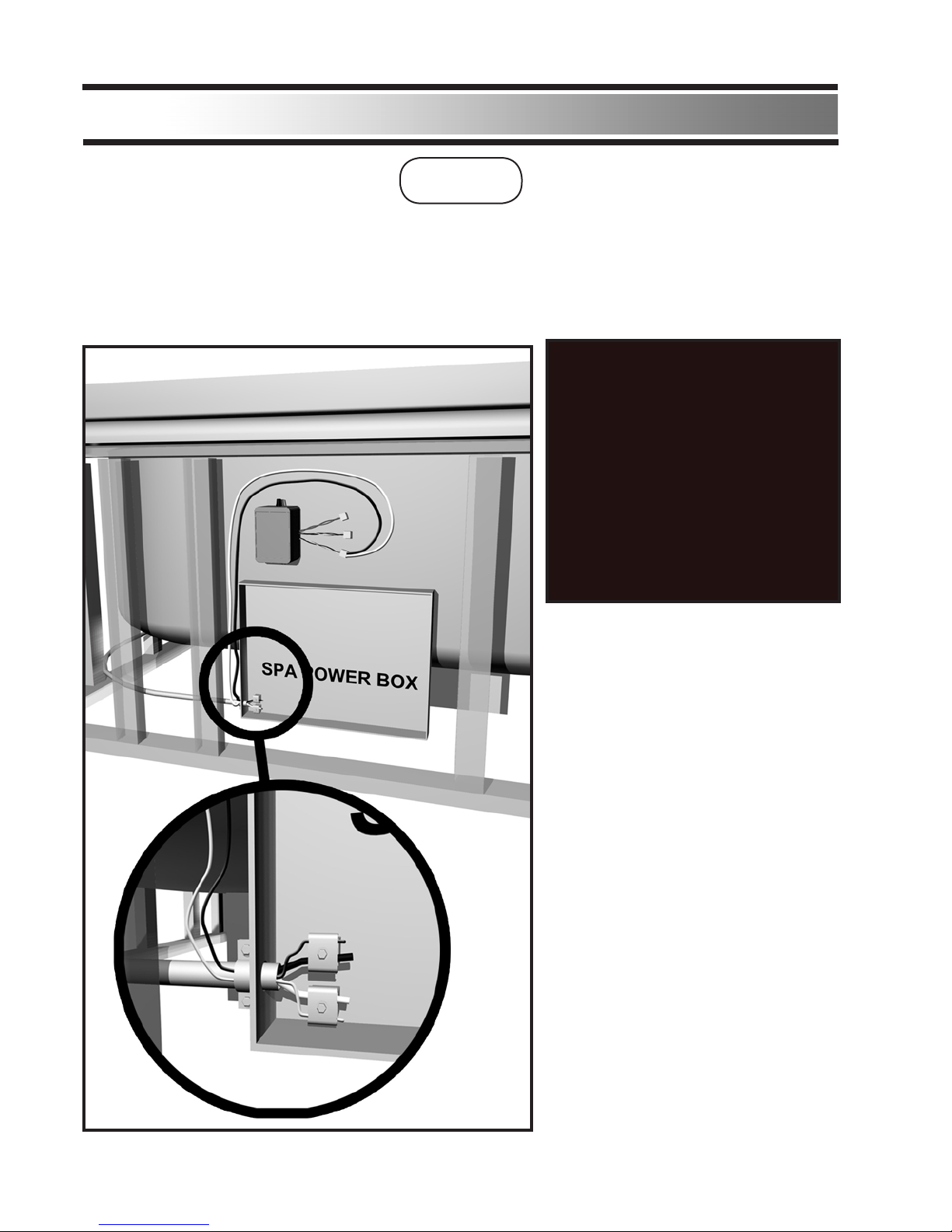
Installing Control Box:
Locate the Spa Power Supply on the
spa. Find a good location for the ASC-2
Control Box as close as possible to the
Spa Power Supply .
Use the 2 Mounting Screws (91555A102)
and mount the ASC-2 Control Box to the
spa.
STEP 2
Final Position
(7)
Mounting Screws
(91555A102) 220 Power Clip
(Green, Black, & White)
110 Power Clip
(Black, & White)
Motor Wire Clip
(Green & White)
STEP 1
Make sure there is sufcient space around the spa for the
ASC-2 to properly operate. The ASC-2 requires 7” of space
on the spa sides for arm clearance. 18” of space on rear
of spa is required for the cover.
18”
7”
7”
SPA
Installation
STEP 3
Take the 2pin BLACK AND WHITE
Wiring Harness and run it into the
Spa Power Box using the same path
as the main line.
(The 110VAC is used mainly for
installation. Use the installer’s AC
power cord to set up the ASC power
system. This can be ordered from
Auto Spa Cover)
(The 110VAC connector has only “2”
wires. 110VAC may be used for main
power if 220VAC is not available.)
Connecting 110-VAC Power to Control Box:
Find out which power level the spa uses. (110VAC or 220VAC)
Remove the Spa Power Box cover. Locate where the main electrical line feeds into the box.
WARNING:
Use a certied electrician to
wire the ASC-2 Control Box
to your Spa Power Box.
Check your electrical panel
box and make sure the power
to the spa is shut off at your
electrical panel.
(8)
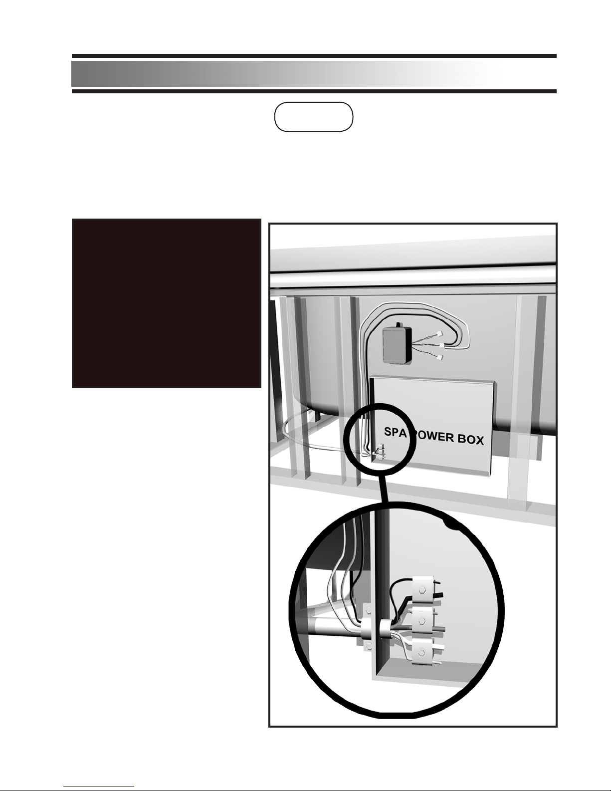
Take the 3pin BLACK, WHITE AND
GREEN Wiring Harness and run it
into the Spa Power Box using the
same path as the main line.
Black=220
White=220
Green=Ground
Attach the Wire Harness to the same
slots that the main line attaches to.
Replace the Spa Power Box Cover.
Plug Wiring Harness into the ASC-2
Control Box.
Installation
Connecting 220-VAC Power to Control Box:
Find out which power level the spa uses. (110VAC or 220VAC)
Remove the Spa Power Box cover. Locate where the main electrical line feeds into the box.
STEP 4
WARNING:
Use a certied electrician to
wire the ASC-2 Control Box
to your Spa Power Box.
Check your electrical panel
box and make sure the power
to the spa is shut off at your
electrical panel.
(9)
Installation
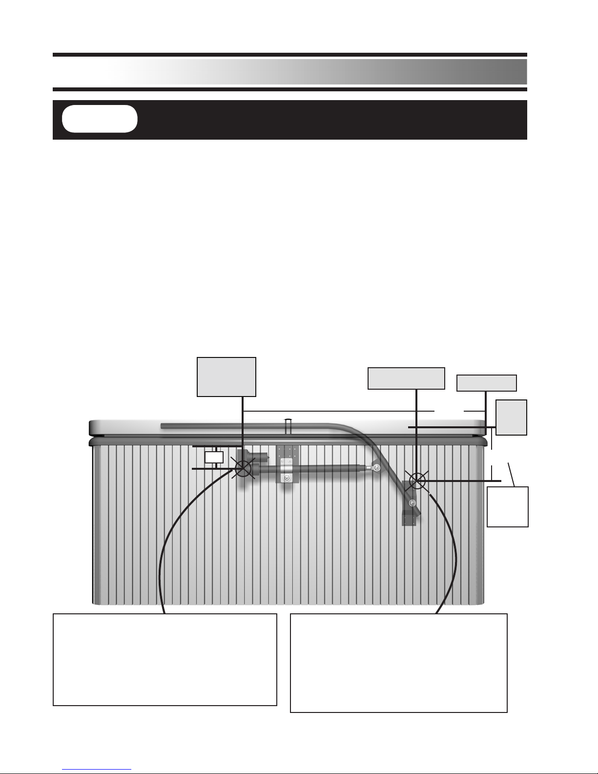
Locating the hardware mounting positions:
Measure 18” from the back of the spa along the side wall. Measure down 14” from the center of
the spa cover. This will be the corner mark for the Side Bar Mount. (For 9ft spas use 21”).
WARNING: DO NOT ATTACH ANY OF THE OUTER HARDWARE TO SPA AT THIS
POINT.
NOTE:
The Motor Wire hole can be adjusted/moved to a different position if the spot is over a spa
stud support.
REAR
OF SPA
FRONT OF SPA
CAUTION - USE THIS GUIDE TO MOUNT THE ASC-2
- FAILURE TO FOLLOW GUIDE WILL VOID WARRANTY -
STEP 5
(10)
18”
Side Bar
Mount Position
Motor
Wire Hole
(optional)
SIDE OF SPA
Measure 18” from back of the Spa and 14” down
from the center of the Spa Cover and make a
mark. This will be the spot where the Top Edge
(closest to the back of the spa) of the Side Bar
Mount will be mounted.
For 9ft size spas use 21” instead of 18”
14”
Center
of Spa
Cover
Back of Spa
7”
OPTIONAL:
Measure 7” down from the bottom edge
of the Spa Fiberglass Shell and 9” to 12”
over from the Motor Mount Position. This
will be the mark for drilling a hole for the
Motor Wiring.
Use 15”
for 6ft &
7ft spas
Installation
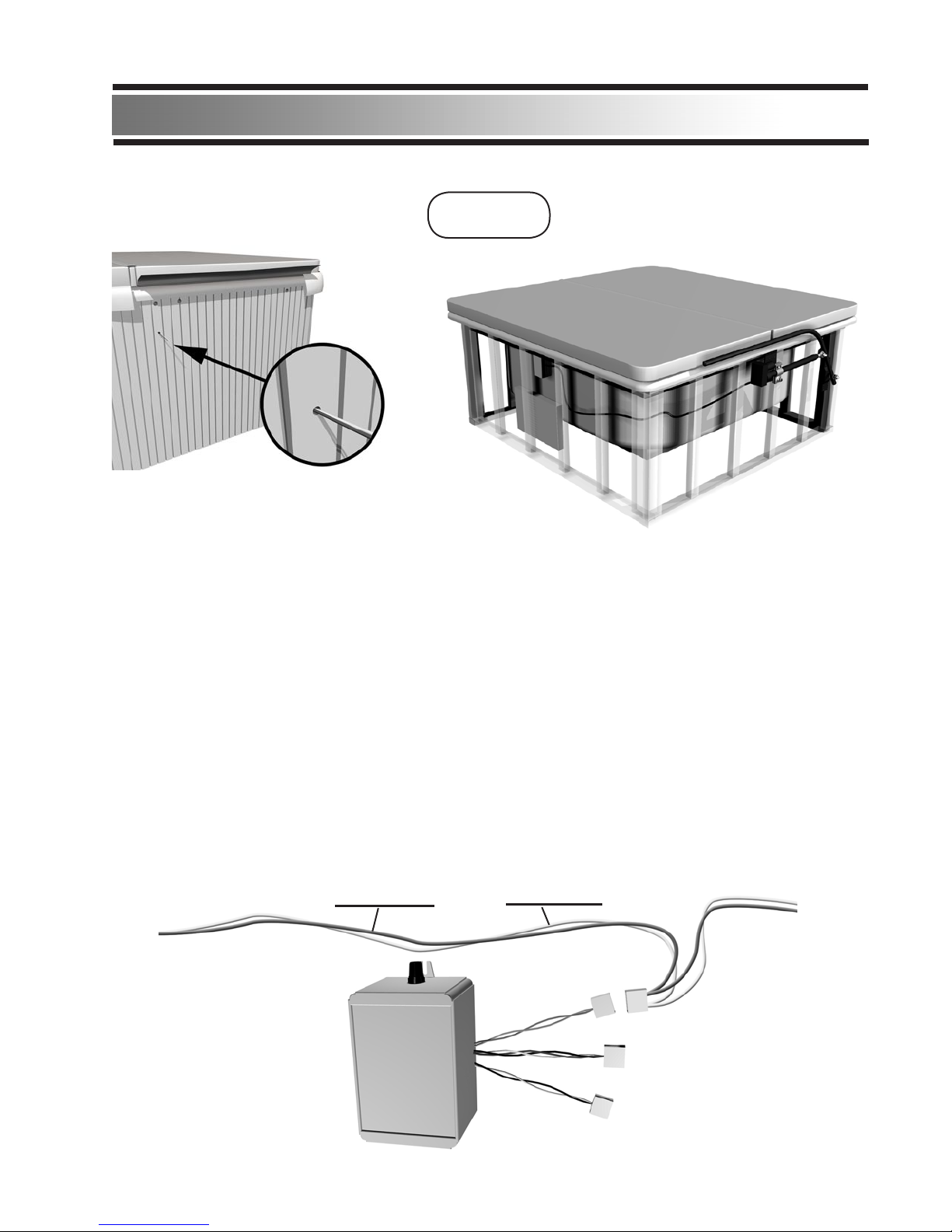
Routing the motor wires:
The Motor Wires need to be routed to the control box location, this can be done several
ways:
1. Between the siding and the supports.
2. Through the side of the spa siding.
3. Down the side of the spa and along the bottom ange of the supports.
If the Motor Wires “through spa wall option” is used, drill a 1/4” hole at the Motor Wire
mark that was previously determined in step 5.
Keep the wires from being crimped by the siding or other components , route the wires inside
of the supports for the siding having them end up at the control box ( leave extra wire length
for future installations )
Attach the Motor Wiring Harness to the Control Box. (Green/White Wires)
STEP 6
Green Wire White Wire
FRONT
REAR
(11)
STEP 7
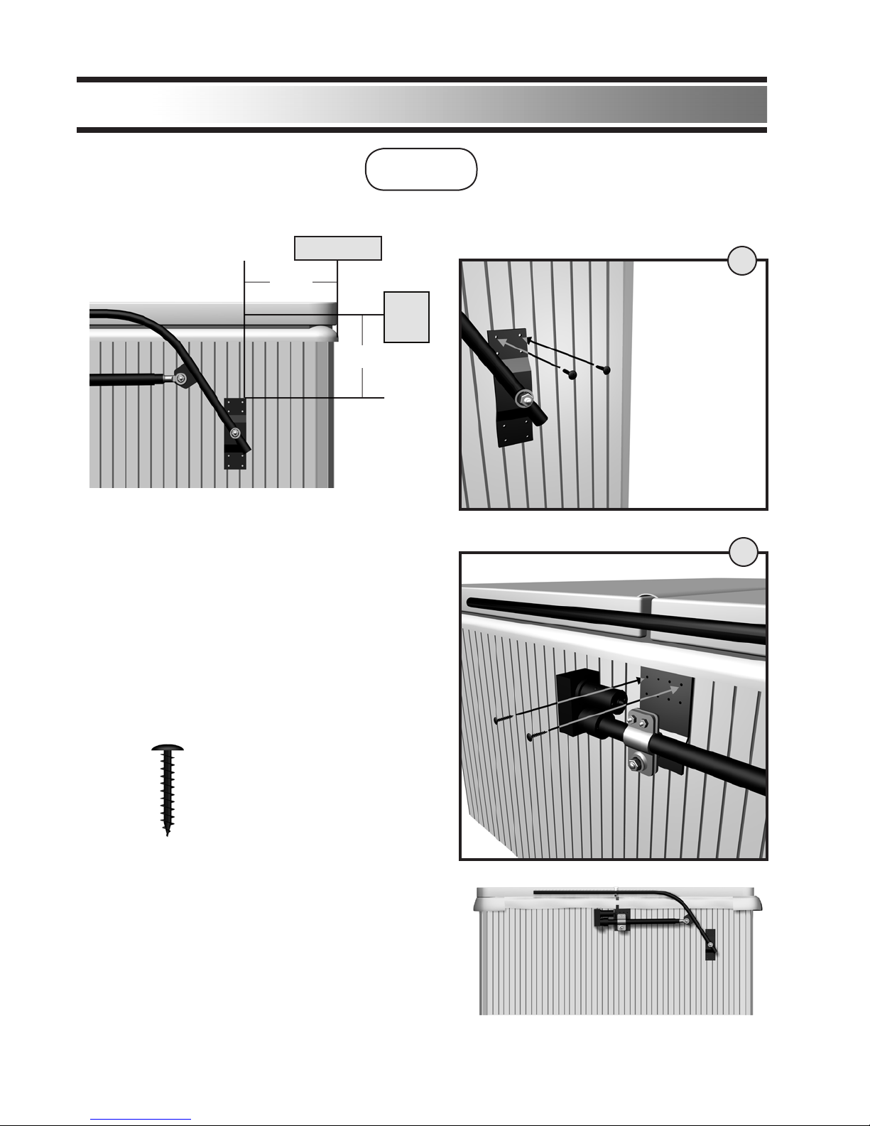
Attaching the Side Bar Assemblies to Spa:
Installation
Attach the Motor Assemblies to the spa. Line
up the ASC-2 Brackets to the guides you
marked earlier and attach using the supplied
Wood Screws (part#1024APTB).
Center the Side Bar Mount (1) over the mark
made in step 5 (pg 10) and attach to spa wall
using 2 wood screws. Next, place the Motor
Mount (2) directly underneath the spa ber-
glass shell lip and attach with 2 wood screws.
1 1/2” Wood Screw
(1024APTB)
(12)
1
2
Check to see if everything placed in their proper
locations and nish inserting the wood screws. If
parts do not line up properly go back and repeat
step 5.
The Motor Assemblies on the spa should look
like the picture on the right.
18”
14”
Back of Spa
Center
of Spa
Cover
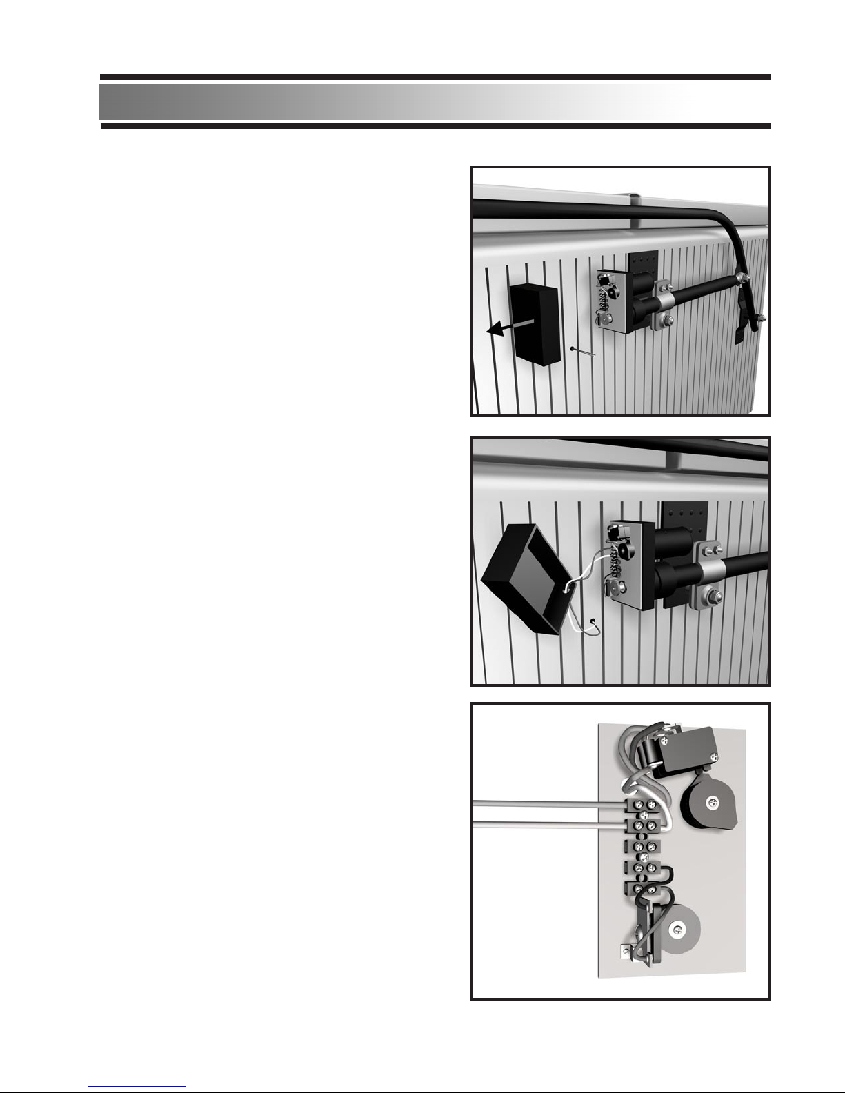
Installation
Wiring up the Motors:
Remove the back covers from the motors.
Place the motor wires protruding from the spa
and run them through the hole on the bottom of
the motor cover.
Attach the Motor Wire to the motors. Make sure
the green/white wires match up to the green/white
wires on the motor.
IMPORTANT: DO NOT CROSS WIRES. WIRES
MUST CONNECT TO MATCHING COLORS.
When completed, re-attach motor covers.
Green Wire
White Wire
(13)
STEP 8
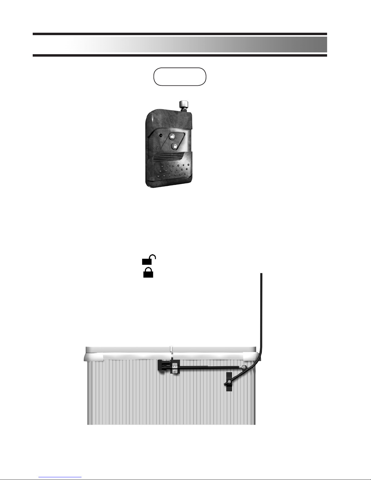
Correct Position:
(14)
The Side Bars should travel towards the back of the spa and stop as shown.
Turn power back on to spa or use the installers 110VAC Power Adapter.
The ASC-2 Assembly will travel to the open position and stop. The ASC-2
Side Bars should stop at the same position.
Use the Remote Control to raise and lower the Side Bars.
To open spa press: or “B”
To close spa press: or “A”
Stand by Power Switch in case of failure.
Installation
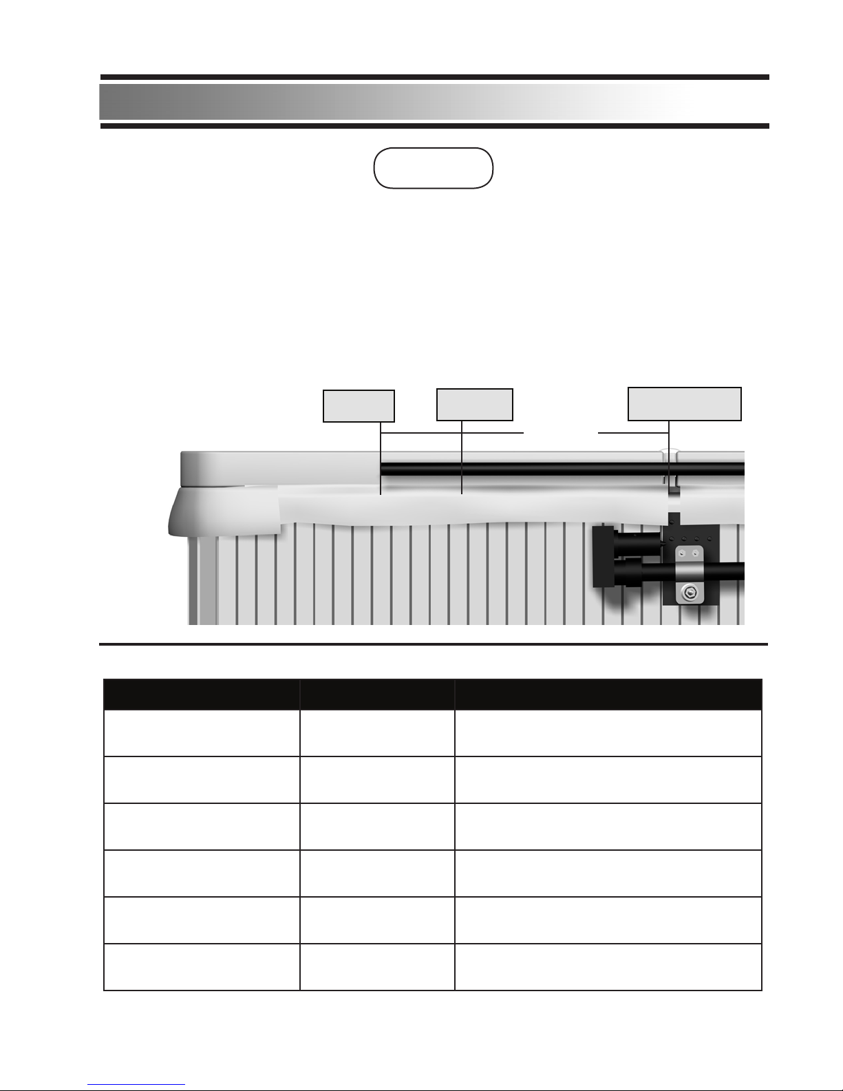
Installing the “C” clamps:
STEP 9
(15)
The unit comes with 2 “C” clamps that are attached to the front half of the cover. These need
to be installed under the vinyl cover.
Use the “C” Clamp Position Installation Chart below to nd where the “C” Clamp needs
to be installed. Use the size of your spa as a starting guide.
End of
Side Bar
“C” Clamp
mark
Center of
Spa Cover
Reference
Measurement
for “C” Clamp
“C” Clamp Position Installation Chart
Spa Size “C” Clamp Stop Bolt Position from “C” Clamp
6ft 21” 7”
7ft 22” 8”
7½ft 20” 5”
8ft 18” 5”
8½ft 18” 6”
Over 9ft 18” 7½” or 21” from back of spa Side Bar
Mounting Point
Installation
Remove the front half of the cover.
Outside Edge Inside Edge
Installing the “C” clamps CONTINUED:
(16)
Side Bar
Reference Measurement
for “C” Clamp
Inside Edge of
Spa Cover
End of
Side Bar
“C” Clamp
mark
Using the “C” Clamp Position Installation Guide, use the length from the “C” Clamp Column
and measure from the inside edge of the spa cover foam insert towards the back edge of the
spa cover foam insert and make a mark.
This will be the position where the “C” Clamp will be centered and attached to the spa cover
foam insert.
Installation
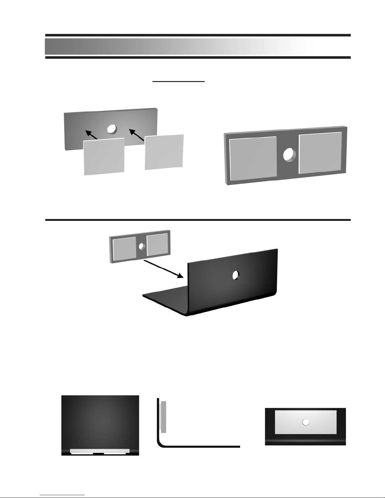
Installing the “C” clamps CONTINUED:
(17)
Apply 2 small strips of double sided tape to the Shoulder Bolt Mounting Plate as shown.
Press the Shoulder Bolt Mounting Plate onto the C Clamp. Make sure the holes line up
before pressing the 2 parts together. The 2 parts together should look like the illustrations
below.
Double
Sided Tape
Ball Joint Mounting Plate
Double
Sided Tape
Final Look
Shoulder Bolt Mounting Plate
“C” Clamp with hole for Shoulder Bolt
Installation
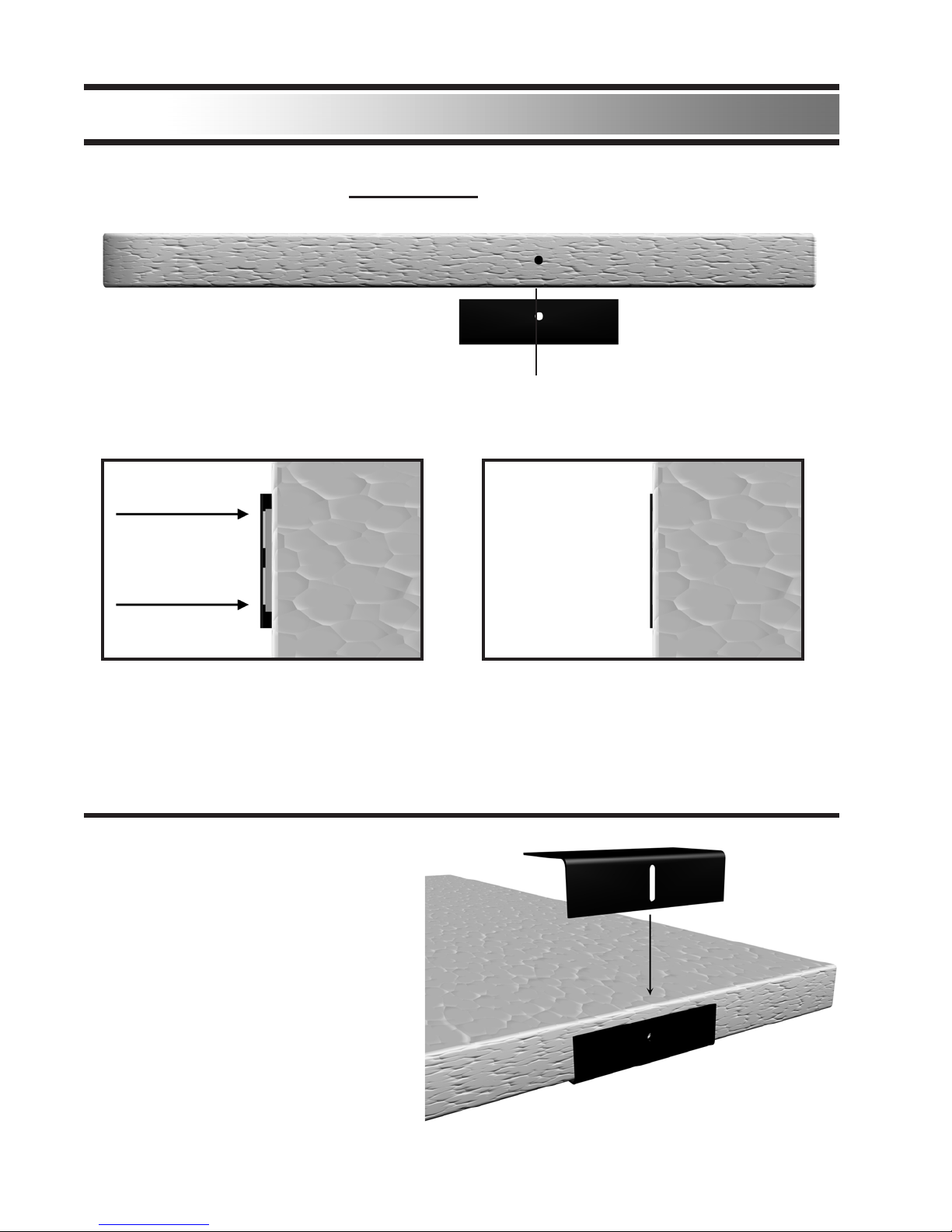
Take the second C clamp and place
it over the bottom piece with the slot
lining up with screw hole.
Perform these instructions to both sides
of the cover.
Line up the C Clamp (with the attached Shoulder Bolt Mounting Plate) to the alignment mark
on the cover.
Press the C Clamp assembly into the foam surface of the cover until the Shoulder Bolt
Mounting Plate is ush with the edge as shown.
Doing this will make the C Clamp assembly t better into the spa cover and avoid possible
tearing of the vinyl fabric.
Press into foam
Installing the “C” clamps CONTINUED:
(18)
Installation
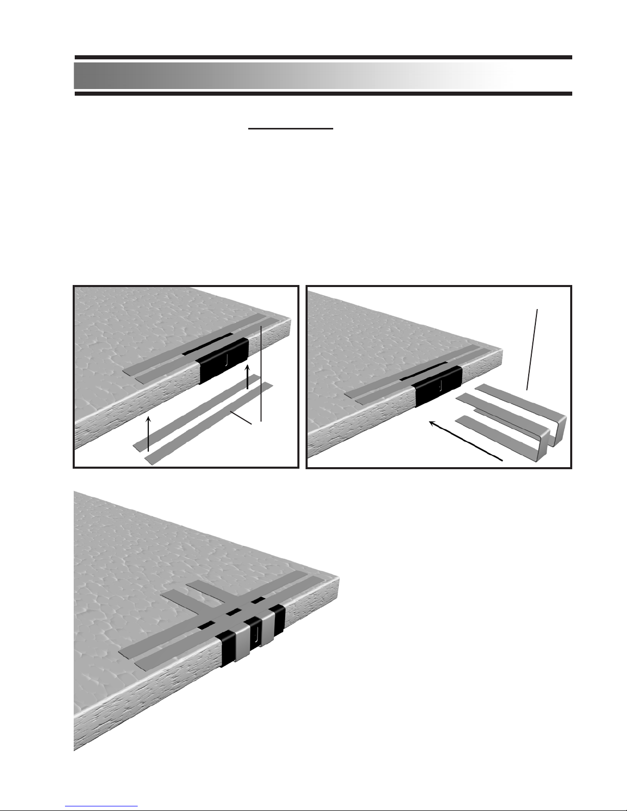
Take the Duct Tape and run 2 pieces lengthwise along the top of cover to hold C Clamp
assembly in place. Repeat along the bottom half of the cover.
Next, place 1 strip of Duct Tape on each side of the C Clamp running perpendicular to the
previously placed Duct Tape.
MAKE SURE THAT THE SHOULDER BOLT MOUNTING HOLE IS NOT COVERED BY
DUCT TAPE. Repeat this for both sides of the C clamp.
Duct Tape
Duct Tape
Installing the “C” clamps CONTINUED:
Final Look
(19)
Installation
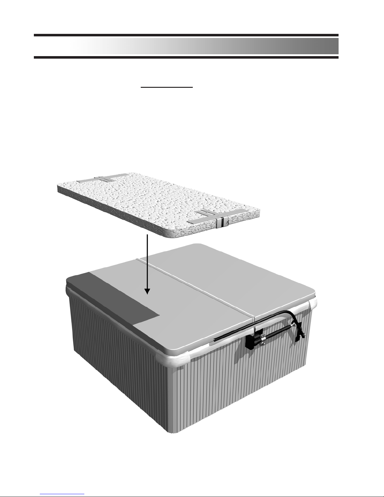
Re-insert the foam into the cover sleeve. Close the zipper on the cover.
NOTE:
DO NOT RIP COVER WHEN RE-INSERTING FOAM INTO SPA COVER.
Installing the “C” clamps CONTINUED:
FRONT
REAR
(20)
Installation
Table of contents
Popular Hot Tub manuals by other brands


 owner's manual")


CalderaSpas
CalderaSpas CalderaSpas Utopia Series owner's manual

anko
anko SS-601A user manual

CalderaSpas
CalderaSpas CANTABRIA owner's manual

Dimension One Spas
Dimension One Spas HYDRO SPORT Installation and owner's guide

Bestway
Bestway Lay-Z-Spa Maldives HydroJet Pro manual

Dimension One Spas
Dimension One Spas Nautilus Specifications