Autobox HIPAK 2675 Assembly instructions
HIPAK 2675 BOXMAKER
OPERATOR INSTRUCTION MANUAL
(2008 version with Rubber Roller and Servo Blade Drive)
Updated: December 2007 - KJP
Autobox Ltd, Unit S1 Cherrycourt Way, Leighton Buzzard, Beds. LU7 4UH U.K.
Tel: +44(0)1525-379 359 Fax: +44(0)1525-382 353
e-mail: info@autobox.co.uk. website: www.autobox.co.uk

2
CONTENTS
Introduction . . . . . 3
Installation . . . . 4
Safety . . . . . . 5
Box Styles . . . . 6
Operator Controls . . . 7-8
Main Menu . . . . . 9
Make a New Box . . . . 9
Screens . . . . . 10-11
Feeding Blanks . . . . 12
Making Base/Lid Boxes . . 12
Making 0933 Divisions . . . 12
Making Flip-Top Boxes . . . 13
The Self-Design (12-Slot) Program . . 13
Using the Auto-Feeder . . . 14
Calibration . . . . . 15-17
Error Messages . . . . 17
Trouble Shooting . . . . 18
Maintenance . . . . . 19
Sensors . . . . . 20
Wiring Schematic . . . . 21-25
Service Spares. . . . . 26-27
Replace Compact Flashcard . . . 28
Warranty . . . . . 29
CE Conformity Certificate . . . 30
3-Phase wiring . . . . 31

3
INTRODUCTION
The Autobox HIPAK 2675 Boxmaker is a sophisticated machine for conversion of
various corrugated board grades into cartons. It is designed for conversion of all grades
of single-wall corrugated and up to 300K/300T AA double-wall.
The Boxmaker utilises a powerful PC with colour touch-screen to reduce the effort of
calculation and set-up time to a minimum. Most styles of box may be made and many
are pre-programmed, requiring only the dimensions to be entered.
Read this manual carefully before using the Boxmaker and ensure that all personnel
required to use the machine are familiar with its contents are given access to this manual
at all times.

4
INSTALLATION
LIFTING
The HIPAK Boxmaker will usually be delivered on a pallet. A forklift truck must be
used when lifting it. Great care must be taken, as the centre of gravity of the HIPAK is
high. Occasionally the HIPAK may be delivered un-palletised, when lifting must be
accomplished from the rear of the machine to prevent tipping.
If a machine is palletised, it will be secured to the pallet with brackets to aid stability.
ENVIRONMENT
Ensure that the machine is mounted on a level surface and bear in mind the weight when
selecting a site. Allow enough space around the HIPAK to handle materials. Extremes
of temperature should be avoided.
The HIPAK is supplied with a motorised conveyor table to ease handling of large
blanks. This is positioned behind the machine, and in front of the catcher table.
A competent, qualified engineer must make all connections to the machine.
Electrical connections to the conveyor from the Boxmaker are via plug and socket.
ELECTRICAL SUPPLY CONNECTIONS
The HIPAK requires a 415V 3 phase and neutral 50Hz supply, at 10A per phase.
Connections are made via the isolator on the left hand side of the machine. Entry is by
cable gland.
For electrical connections, consult the diagram provided at the back of this manual.
A PROTECTIVE EARTH MUST BE PROVIDED.
DISMANTLING
If for any reason, the machine has to be dismantled or removed, full details of the
correct procedure may be obtained by contacting The Technical Department at Autobox
Limited.
Under no circumstances must a person dismantle the machine without instructions being
given by the Autobox Technical Department.

5
SAFETY.
GUARDING
The guarding fitted to your machine is there for your safety. Do not attempt to remove
it at any time. Ensure that it is firmly fixed in place at all times. If the guarding has to
be removed for maintenance etc., it should be undertaken by a suitably qualified
engineer under the instruction and guidance of an Autobox engineer. Please ensure that
the electrical supply is disconnected before removing guarding for any reason. If there is
reason for the electronics to be exposed, the machine must be left for two minutes after
disconnecting the power supply as some components retain current after the machine is
powered down.
If maintenance requires removal of guarding whilst the electrical supply is still
connected, please refer to the maintenance section at the back of this manual and always
ensure that only qualified personnel carry out the procedures.
Remember that powered components and high voltages can be very dangerous when
exposed.
SAFE USAGE
Only use the Boxmaker with the materials recommended for conversion, other materials
might cause damage and/or hazards. Always use light gloves when handling corrugated
materials to avoid paper cuts.
Make sure long hair, loose clothing, etc. are made safe before using the machine.
NOISE LEVELS
Noise levels will vary depending upon weight of board in use, location, etc.

6
Box Styles Programmed into the HIPAK 2675 Boxmaker
½SC

7
OPERATOR CONTROLS
CONTROL FUNCTIONS.
TOUCH SCREEN
The touch screen is the Human-Machine Interface used to select box style, input
dimensions, monitor progress, store and read back boxes, etc.
CREASE LEVER
The crease lever is used to set the depth of the creases along the box. When the lever
points down maximum creasing pressure is applied. Moving the lever upwards reduces
the creasing pressure for lighter creases or for heavier board.
It is recommended that a piece of scrap board be passed through the machine to test the
crease prior to making the first box.
GUIDE/BLADE ADJUSTMENT
A crank handle and a toggle switch are fitted to the side of the machine for adjusting the
board guides and blade. When a box program has been selected, the display will show a
blank size and two settings. The first setting relates to the smaller orange dial on the
end of the machine. It is the slot depth in millimetres and is set using the crank handle.
The second setting is the distance between the slots and this dimension is set on the
larger counter by pushing the switch up to increase, or down to decrease, until the
number shown is the same as that on the display.
Note:
The extreme right hand digit on both dials indicates 0.1mm i.e. to correctly enter a
setting of 100mm the dial should read 100.0
Switch to adjust
‘Setting 2’
Crease Lever
Touch Screen
Crank Handle to
adjust ‘Setting 1’
Conveyor On/Off
and speed adjust
EMERGENCY STOP
Primary 3
-
Phase
Isolator and
Start/Stop
Feeder Gate
Large Counter
Small Counter
Left-Hand Guide

8
DIVISION LEVERS
The division levers are positioned on both sides of the lower back of the machine and
are used when making 0933 divisions.
For most box styles, the levers should be in one of the lower positions to give a crease
across the board between the slots. When making divisions this crease is not required,
so the levers should be moved to the highest position to prevent creasing.
Remember to move both levers back to the lower position before continuing with
normal box making.
It is very important that both levers are fixed in the same position before the machine is
operated.
STARTING
Before starting the machine, first check that the immediate area is clear and that there
are no obstructions under the blade.
Switch on the isolator and press the green, start switch.
The P.C. will ‘boot up’ and the display will show the main menu indicating that it is
ready to be programmed.
The ‘boot up’ screen will show for several seconds during the start process and this
includes a message indicating the number of boxes to be produced before the
recommended service.
It should be noted that the servo unit, that drives the blade, will go through a ‘homing’
sequence to ‘park’ the blade at Top Dead Centre when it is first switched on. If the
blade is already at the TDC position, then there may be an audible noise as the brake is
released then immediately applied again. This is normal.
STOPPING
To stop the machine, press the red, stop button. This will switch off the 3-phase power
that drives the machine and will apply the brake to the blade drive.
To switch off completely, i.e. at the end of the day, switch off the primary, 3-phase
isolator.
In an emergency, press the E-stop button. This will lock in place and must be twisted to
reset.
RATING PLATE
The rating plate, fitted to the end panel, displays Model number, Serial number,
manufacturer contact details, power requirements, etc. This information will be required
by Autobox in the event of any enquiry concerning service or spare parts.

9
MAIN MENU
This will appear when the machine is first started.
Return to Main Menu at any time by touching
the ‘Menu’ button or the ‘Back’ button
TO MAKE A NEW BOX
Touch ‘Make New Box’ in menu.
Touch required box style or ‘menu’ to go back
Select variant where available
Touch ***** to enter dimensions and
numeric keypad will appear on screen
Enter dimension and touch to continue,
to go back or to cancel
When required dimensions are correct, touch
‘Enter’ to continue
Set back guide and blade to ‘Blade Settings’, cut blanks to size
and touch ‘continue’
Set crease lever according to board thickness – at lowest point for thin board and
approximately horizontal for double-wall board. This will vary according to paper
grade, humidity, board thickness and the preferred depth of crease.
Machine is now ready to make boxes.
Place blank on table with inner face up and held gently against the left-hand guide.
Push positively into machine until roller grabs it and continues automatically.

10
SCREENS
The ‘Run’ screen is displayed while making boxes. It displays the
time and date, the box style being made and the number made.
It also allows the operator to select several options including;
save the current box to memory, check the dimensions entered,
adjust the throughput speed or return to the ‘Main Menu’.
‘Running Speed’ and ‘Running Accel’ allows the operator to select the ideal throughput
speed and acceleration rate for making each box accurately and comfortably. Some
large, heavy boxes will need to be run at a slower speed just as very small boxes will
also need to be run slowly to prevent ‘snatching’. For best results, always select a slow
speed, say 20%, and then increase if possible.
‘Last Box Time’ shows the time taken for the previous box to pass through the machine.
This may be useful for batch costing or calculating accurate production times.
Selecting ‘Batch info’ allows the operator to enter the size of a batch to be run. The
‘Number Made’ will then count down from that number
until the batch is completed at ‘0’.
The start and finish times will then be recorded in the Batch Log.
To run a batch, first touch ‘Reset’ to clear the previous data, then
touch the ‘size’ to enter the number of boxes to be run.
Touching the ‘back arrow’ will return to the ‘Run’ screen.
When a batch is cleared, set up and completed in this way, it will be automatically
recorded in the ‘Batch Log’. This can be viewed at any time for a record of productivity.
‘Panel Size’ shows a list of the actual measurements of the box
panels. These include allowances based on the board thickness
entered by the operator.
To check the size of the box, measure the flat box from leading
edge to centre of first slot, then from centre of slot to centre of slot
to check subsequent panels.
‘Dimensions’ will return to the box dimensions that have been entered for confirmation
or to make changes.
‘Base/Lid’ is used when making 0300 and 0301 boxes to switch from the base to the lid
and back. The machine will always default to ‘base’ when entering the dimensions.
Switching to ‘Lid’ will increase the dimensions by the appropriate amount to fit over
the base. Note that the lid will require a larger board blank than the base.
11
SAVING BOXES INTO MEMORY
Touching ‘Save’ will allow the current box to be entered into the
memory for future use.
The virtual alpha-numeric keyboard can be used to give each box a
code, or name, for identification.
MEMORY
The memory can be accessed via the main menu or from other
screens by touching the button.
SAVED BOXES
Touch ‘Saved Boxes’ button to display the list of saved boxes.
These will be saved in alphanumeric order. To reduce the search
time, touch the ‘Goto’ button and enter a letter on the keyboard
that will appear on screen. The cursor will jump to the section
starting with that letter.
Use the up/down arrows to move the cursor to the box required
and touch the ‘Run Program’ button.
Set the guide, prepare the blanks and the machine is ready to use.
CURRENT PRODUCTION DATA
Enter a month and day to recall the number of boxes made on that
day.
ARCHIVE PRODUCTION DATA
At the beginning of each year, the previous year’s production can
Be recorded into the permanent memory. The total number of boxes
produced to date is also displayed.
SYSTEM CONFIGURATION
Touch ‘Configure System’ on main menu.
This screen allows the operator to set the time and date, change
from inches to millimetres and select language.
Engineering parameters are protected by a password.
MANUAL SYSTEM CONTROL
Select ‘Manual Control’ from main menu.
DIAGNOSTICS
Touch and hold the ‘Test Roller’ button to run the board feed roller
or ‘Test Cut’ to operate the blade.
Pushing a piece of board into the machine should operate ‘Sensor 1’,
‘Sensor2’ and ‘Encoder’ to ensure that all are functioning correctly.
MANUAL JOG
Allows the board to be fed into, or out of, the machine.
This screen will automatically appear if a board jams in the
machine. Once the board is cleared, touching the ‘back arrow’ will
return to the run screen.

12
FEEDING IN THE BLANKS.
The blanks (already cut to the correct size) must be fed into the machine held gently
against the left-hand guide to keep them square and must have the inside of the box (the
test or liner) facing up. The right-hand guide is provided to help keep the blanks square.
This should be locked in place leaving 1 or 2mm clear to allow the blanks to slide freely
into the machine.
As each box is converted the 'number made' will increase on the display to keep an
accurate record of each production run.
The blanks can be fed manually, one at a time, or can be fed from the auto-feeder where
fitted. See section on ‘Using the Auto-Feeder’.
0300 AND 0320 BASE AND LID
When making boxes that consist of a base and lid, enter the internal dimensions
required and the base will be calculated to fit these dimensions while the lid will be
automatically calculated to fit over the base. For this reason the two blanks will be
slightly different sizes.
To change from producing the base to the lid and back, touch the ‘Base/Lid’ button at
the bottom of the screen.
Note: In some cases, a deep base may be required with a shallow lid i.e. a 300mm base
with a 100mm lid but the machine will automatically calculate the lid to be the same
height as the base. To change this, first make the number of bases required then touch
the ‘Base/Lid’ button followed by the ‘Dimensions’ button. The height dimension can
then be altered.
The blanks may now be cut to size and the lids will be made to fit over the bases but the
depth will be reduced.
0933 DIVISIONS.
A different set of parameters is required for divisions. Instead of the normal 'Length,
Width and Height', the display will now show 'No. of cells, width, height, thickness and
time'. Enter the dimensions for the required divisions and leave the 'time' set at zero; this
is only used on pneumatic machines.
Before running the blanks through the machine move the division levers at the lower,
back of the machine, to the top position. This will stop the crease forming between the
slots.
Remember to replace the levers to the original position before continuing with other box
programs or there will be no crease between the slots.
The computer will automatically calculate a blank of twice the width to allow two
pieces to be made in each pass. These can then be slit down the centre. This doubles
productivity by utilising both blades.
If it is preferred to make only one at a time, simply cut the blanks to half the width
shown and set the machine as the on-screen instructions.

13
TO MAKE FLIP TOP BOXES.
Enter dimensions as for other box styles but note the following:
The flip top flap is 75mm when the height is 60mm or less. When the height is over
60mm, the flap will be 125% of the height. Minimum length is 155mm.
The flip-top box is measured as shown.
SELF-DESIGN (12 SLOT) PROGRAM.
This program is used to make unusual boxes or fittings, or it can be used to make
standard boxes if all the dimensions are already known. Up to twelve dimensions can
be entered. The first dimension entered will be from the front edge of the board to the
centre of the first slot. Subsequent entries are from the centre of the previous slot to the
centre of the next slot.
Only one blank dimension is displayed and this is the total of the entries made plus the
glue flap. The machine does not calculate the blank width and setting – this must be
done manually.
Length
Width
Height

14
USING THE AUTO FEEDER (IF FITTED)
The automated sheet feeder fitted to your HIPAK consists of a free-standing board
support, as well as the gates, guides and roller assembly on the front table-top.
To operate the feeder, first cut the blanks to size and set up the machine guide and
moving blade as described in the previous pages.
Take one blank, place it against the left-hand guide and set the right-hand guide
approximately 1 or 2mm from it and lock in position with the handle on the front.
It is important to set the right-hand guide loosely to allow the blanks to slide freely into
the machine.
Next, set the gates, (or one gate if making a small box) by sliding the blank under it and
lowering the gate by turning the black plastic knob on the top.
When set correctly the blank should slide forward freely under the gate but there should
be a resistance when pulled back. This shows that the blank is being firmly gripped.
When this has been correctly set, the board support can be pushed into place so that,
when the stack of blanks is placed between the guides and is butted up against the gates,
the end of the stack rests on the lower edge of the angled support.
For larger blanks, an adjustable roller is provided to support the stack and prevent the
blanks from bending. If needed, this should be set so that it is just barely supporting the
stack but not taking all the weight.
When this is done, and the display shows the ‘Ready’ screen, the Auto Feeder ‘Start’
button should be pressed to start it running. Pressing the ‘Stop’ key will stop the feeder.
If the feeder has been set up correctly, each board will be pulled from under the stack,
the back end will immediately fall off the edge of the angled support and it will be fed
into the machine.
There is a safety switch fitted into the tabletop that will stop the feeder if the stack of
board runs out. To start again, replenish the stack and press the 'Start' switch again.
If the automatic feeder is not required, i.e. for a short run, then the two gates can be slid
off the rail to the left and the machine can be used manually.
The number of blanks to be stacked on the feeder will be determined by size and weight
as the bottom blank is pulled out from below. If the stack is too heavy, the boards will
jam and a few should be removed from the top of the stack.
Warped or damaged board may jam in the feeder and should, therefore, be avoided.

15
Hipak 2675/2670 Calibration procedure
As with any electro-mechanical machine, the electronics and mechanics have to be synchronised to
gain maximum performance and accuracy.
The following are instructions for calibrating a Hipak machine with ‘Generation 7’ touch screen
control system. This should normally only be carried out when the machine is first built but,
following servicing, repairs or software upgrades, some further calibration may become necessary.
Calibrating box sizes should always be carried out in the following order:
1. ‘Encoder Setup’ – Set panel sizes but ignore panel 1.
2. ‘Offset – Blade to Sensor 2’ – Set panel 1.
To enter ‘Engineering Setup’ screen:
Select ‘Configure System’, ‘Engineering Parameters’ and Enter Password………
‘Running Parameters’
Running Speed – This shows the speed selected by the operator from the
‘Run’ screen.
Jog Speed – This shows the speed selected by the operator from the ‘Manual
Jog’ screen.
Offset Distance – This is the distance in mm from main blade to sensor 2. Adjusting this offset will
change the length of the first panel of each box.
Nominal setting is 75mm. A larger offset will give a longer first panel.
Number of Boxes to Service – This is set to remind the operator when a service is due.
When the system boots up the screen will show ‘Service Due at……’. The set number will reduce
by the number of boxes made until, at zero, the screen will show ‘Service Due’. Nominal setting is
500,000 which is the average production for six months.
The ‘Service Complete’ button should be pressed, after servicing, to reset.
Move Adjustment Percentage – This is used to set the ratio of the linear movement of the corrugated
board to the number of turns of the motor, which affects the last panel of a box. Under normal
conditions the board travel is monitored by both the surface encoder and the motor encoder with
constant comparisons and corrections electronically. When a box is made with a glue flap of less
than 50mm, the last panel is measured only by the motor encoder and so this has to be calibrated
correctly to take account of any tolerances in the manufacturing process of the knurled roller or
pulleys.
Nominal setting is 0.0. A positive setting will give a longer panel. Negative will be shorter.
16
‘Encoder Setup’
Wheel circumference – this is the size of the knurled wheel on the surface of
the board.
Nominal setting is 200.0mm. A larger setting, say 200.4, will make all box
panels smaller.
‘Calibrate Screen’
Carefully touch each target as it appears on the screen to automatically
synchronise each target to the area touched.
‘Move Test’ This is normally only used by Autobox engineers to check encoder
calibration. Touch ‘Switch Controller Off’ and push a suitable length of
board into the machine. Select ‘Board Encoder’ or ‘Motor Encoder’. Select
suitable Move Distance, Accel/Decel rate and Board Speed (Nominal 50%).
Touch ‘Start Move’ to check distance moved.
‘Burn In’
This is a repetitive cycle to ‘bed in’ the motor drive and the blades/knives.
When started, the roller will turn for one second then stop, the blades will
chop and the cycle will repeat until the ‘Stop’ button is touched.
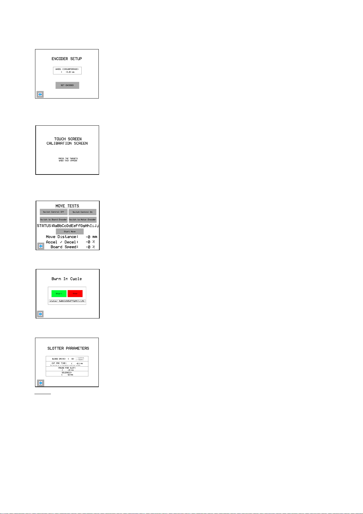
‘Cutter Setup’
Blade Drive – Select 1 for All-Electric or 2 for pneumatic.
Cut Pre Time – This is the time, in ms, that the blade is triggered before the
board actually stops travelling.
Pause for Slot – The time, in ms, that the machine pauses for the blade cycle.
Nominal 350ms for electric blade drive.
Solenoid – The time, in ms, that the solenoid is energised Nominal 100ms.
Note: For pneumatic drive ‘Pause’ and ‘Solenoid’ are 0 as the blade is controlled by cylinder
sensors.

17
‘Change Password’
This enables the owner to enter a password of personal choice.
Any personal password must be made available to Autobox engineers when
needed.
‘Select Motor’ This enables the drive system to be configured to operate with an alternate
motor.
On no account should this be changed without consulting Autobox.
Please Note: The calibration set-up, as detailed above, is intended to allow the machine to be ‘fine
tuned’ to produce consistent, accurate boxes. If the boxes are inconsistent, i.e. the panel sizes are
varying, then the problem will not be solved by re-calibrating. Inconsistencies are caused by
mechanical slippage of the encoder wheel or the drive mechanism, or by the blanks jamming in the
machine.
ERROR MESSAGES
‘Current Drive Error’
This indicates an error in the drive system and is normally seen when the
blade drive motor has not been switched on.
If a ‘lag error’ message is also shown while making a box, this indicates that
the box has not moved through the machine as calculated by the computer.
This may be because the crease wheels are set too light to grip the board, the side guides may be too
tight or there may be a stack of blanks on the Auto-Feeder too heavy to allow the boxes to move
through the machine.
If a box is jammed in the machine and the error message appears, as above, touch the
‘Acknowledge’ button and the ‘Manual Control’ screen will appear. This allows the operator to
drive the box out of the machine, forward or backward, and then touch the ‘Back’ arrow to return to
the ‘Run’ screen and continue.

18
TROUBLESHOOTING
In the unlikely event that your boxmaker does not operate as expected please check the
following:
BOARD NOT ACCEPTED BY MACHINE.
Check that you have fully programmed machine and it is showing a ‘READY’ prompt.
Check that dust or particles of board are not obstructing the light sensors. If this is
suspected then, from ‘Main Menu’ select ‘Manual Control’ and then ‘Diagnostics’.
The screen should show that Sensors 1 and 2 are not made. This will switch to ‘Made’
when a piece of board is pushed into the machine.
If either sensor shows ‘Made’ when there is no board present then it is likely that there
is dirt or debris in the machine and this should be cleaned out to allow the machine to
function.
LAST SLOT MISSING.
This is caused by insufficient board available at the end of the blank, which may be
caused by the blank being cut too short or the preceding panels being too long.
Check that the blank length corresponds to that on the ‘Final Setup’ screen and check
that there is sufficient creasing pressure to grip the blank and pull it through the
machine without slipping.
ADJUSTABLE GUIDE NOISY OR SLOW.
The adjustable back guides and blade may from time to time become slow or noisy to
operate. This can be caused by dust accumulating on the lead screws. It is advisable to
service them occasionally. To gain access to the screws, first disconnect the power
supply and remove the front and rear top guards. Clean the dust from the lead screws
and spray them with a light silicone spray only, the use of grease or oil will cause dust
to build up very quickly, and should be avoided.
The foregoing are some of the more common problems experienced.
If any other problems are experienced, see the section on maintenance.

19
MAINTENANCE
Normal housekeeping procedures should be employed to keep the machine clean and
dry.
Some basic adjustments and maintenance procedures are detailed in the following
pages.
DAILY:
Purge the machine of dust using a suitable vacuum cleaner around the blade and sensor
area or blow out with an airline if safe to do so.
Look under the guard where the board is fed into the machine. The sensors can just be
seen emitting a red light. This area must be kept clean and free from dust and scraps of
paper.
Clear all slotting material and debris away from the outlet chute on the lower, front of
the machine. Never allow the outlet to become obstructed.
Clean the tabletops and guides with a good quality silicone based polish. This helps
reduce friction and makes the machine easier to use.
Failing to polish the tables and guides can cause the board blanks to drag, slip and slew
– this can cause inaccuracies or jamming.

20
SENSORS
Two optical sensors are fitted to the machine to detect the corrugated board entering and
leaving the machine.
The sensor consists of a 24Vdc amplifier unit with digital display, mounted at the top
left corner of the machine, and a fibre-optic cable that is mounted such that the end of
the cable ‘sees’ the corrugated board and emits a red light that is clearly visible to the
human eye.
TO SET UP SENSOR.
Switch on the machine. The red and green numbers will show and a red light will be seen shining
from the end of the fibre.
Press the mode button and hold for three seconds – the number display will be replaced with the
word EASY or FuLL.
Press the manual button – to show FuLL (full access mode).
Press the mode button then press the manual button until display reads rESo (high resolution).
Press the mode button SEVEN (7) times – display will scroll through:
‘toFF ----’,
‘diFF oFF’,
‘Eco oFF’,
‘rE’,
‘Hold’
‘L on rESo’
until red and green numbers show again as above.
It is very important that the display should show the modes listed above. If any of the modes
are incorrect, press the up or down arrow to change.
When all modes are correct and the red and green numbers are displayed, the preset value can be
adjusted as follows:
Press manual button until GREEN number (preset value) reaches the required setting, close the dust
cover, the sensor is now set and will switch when current value reaches the preset value.
Nominal settings are 50 to 70 but should be approximately 50 higher than the red figure when there
is no board in the machine.
Example: If red number is 0, set green number to 50. If red is, say, 17, set green to 70.
1234
1234
Red light
ON when
active Set
button
Preset
value
(green)
Current
value
(red)
Manual button
Preset value
up/down
Mode
button
This manual suits for next models
2
Table of contents


