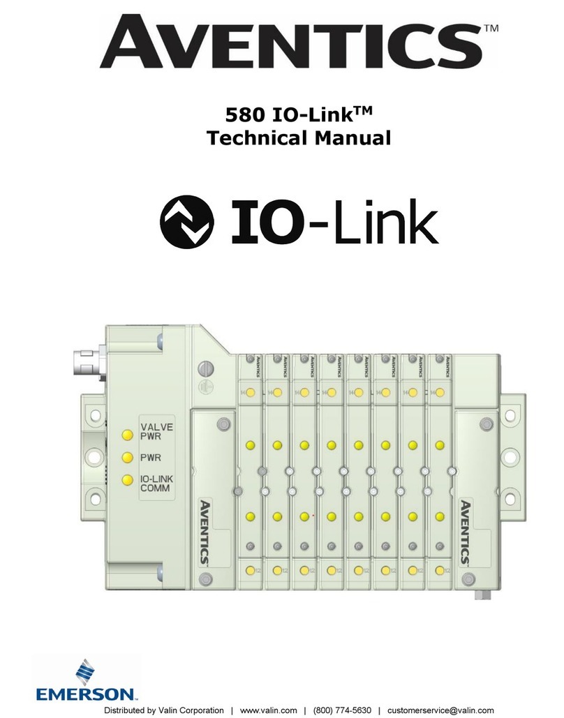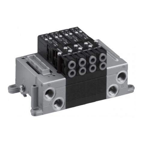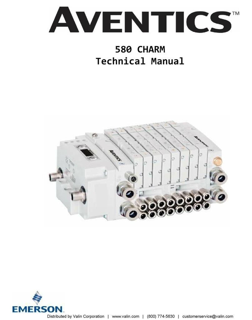
580 PROFIBUSTM DP Technical Manual
1-4
TD580PTTM1-2EN 07/2020
Subject to change without notice
www.asco.com
Table of Contents
PAGE
1. About PROFIBUSTM DP .................................................................................................................................. 1-5
1.1 Overview ........................................................................................................................................... 1-5
1.2 580 PROFIBUSTM DP Node Features ...................................................................................................... 1-5
1.3 Cabling and Drop Line Lengths (as defined by PROFIBUSTM specification) .................................................. 1-5
2. 580 PROFIBUSTM DP Introduction .................................................................................................................. 2-6
2.1 Pneumatic Valve Manifold – 501 Series shown ....................................................................................... 2-7
2.2 Manifold Connectors ........................................................................................................................... 2-8
2.3 Z-Board™ Connectors ......................................................................................................................... 2-9
3. Zoned Power ............................................................................................................................................. 3-10
3.1 503 Series Zoned Power application .................................................................................................... 3-10
3.2 503 Series Zoned Power example ........................................................................................................ 3-11
4. Communication Module ............................................................................................................................... 4-12
4.1 580 PROFIBUSTM DP Node .................................................................................................................. 4-12
4.2 580 Node Description ........................................................................................................................ 4-13
4.3 Connector Pin-Outs ........................................................................................................................... 4-14
4.4 Electrical Connections ........................................................................................................................ 4-15
4.5 Chassis Ground ................................................................................................................................. 4-16
4.6 Power Consumption ........................................................................................................................... 4-17
4.7 Recommended External Fuses............................................................................................................. 4-18
4.8 Diagnostics – 580 PROFIBUSTM DP Node LED Functions .......................................................................... 4-19
5. Extended Coil Capability .............................................................................................................................. 5-20
5.1 Extended Coil Configuration ................................................................................................................ 5-20
5.2 Extended Coil Valve driver IO Mapping ................................................................................................. 5-21
5.3 501 Series, up to 64 solenoid coils ...................................................................................................... 5-22
5.4 501 Series, up to 128 solenoid coils ..................................................................................................... 5-23
5.5 502 and 503 Series, up to 80 coils ...................................................................................................... 5-24
6. 580 PROFIBUSTM DP Node Graphic Display .................................................................................................... 6-25
6.1 Network Address Sub-Menu ................................................................................................................ 6-26
6.2 Set Slave Address Lock Sub-Menu ....................................................................................................... 6-27
6.3 500 Series Extended Coil Capability ..................................................................................................... 6-28
6.4 Advanced Settings – Flip Display ......................................................................................................... 6-29
6.5 Advanced Settings - Parameters ......................................................................................................... 6-30
6.6 Factory Defaults ................................................................................................................................ 6-31
6.8 Diagnostics ....................................................................................................................................... 6-32
6.9 Diagnostics - Self Test Mode ............................................................................................................... 6-33
6.10 Error Messages ................................................................................................................................. 6-34
7. PROFIBUSTM DP Configuration and Mapping ................................................................................................... 7-35
7.1 GSD File ........................................................................................................................................... 7-35
7.2 User Configurable Device Parameters .................................................................................................. 7-35
7.3 Fail Safe Mode Parameter ................................................................................................................... 7-36
7.4 Commissioning 580 ProfibusTM with Siemens TIA Portal Software ............................................................ 7-37
8. PROFIBUSTM DP Mapping ............................................................................................................................. 8-41
8.1 I/O Sizes .......................................................................................................................................... 8-41
8.2 Bit Mapping Rules .............................................................................................................................. 8-41
8.3 Mapping Example No.1 ...................................................................................................................... 8-42
8.4 Mapping Example No.2 ...................................................................................................................... 8-43
9. Appendix................................................................................................................................................... 9-44
9.1 System Specifications ........................................................................................................................ 9-44
9.2 Factory Default Settings ..................................................................................................................... 9-44
9.3 Troubleshooting ................................................................................................................................ 9-44
9.4 Glossary of Terms ............................................................................................................................. 9-45
9.5 Technical Support.............................................................................................................................. 9-45
Distributed
by
Valin
Corporation
|
www.valin.com
|
(800)
774-5630
|
[email protected]