Ice NPRG860 User manual

NPRG 860 – NPRG 870
User’s Guide Issue : b File : A429B Date : 09/2010
This document is the sole property of ICE. No duplication nor release to third party is allowed without prior authorization.
NPRG860 – NPRG870
User Guide
Digital Automatic Synchronizer

This document is the sole property of
ICE. No duplication nor release to third
party is allowed without prior
authorization.
NPRG 870 – NPRG 860
User’s Guide Date : 09/2010
Edition :13/06/2017 Sheet : 1
Issue : D
FOREWORD
This aim of the handbook is to provide to the User information useful for the operation of the
NPRG 860 and NPRG 870 Automatic Synchronizer devices with the local MMI, without
configuration PC. It comes in complement from the First Handling Guide.
We advise you to read it carefully, in order to take note of the available functionalities and to
proceed to connection and power of the product in accordance with the provided
recommendations.
Locally, setting, commissioning and real time or event readings are accessible from keyboard
and displayed on the Automatic Synchronizer device.
To be fully exploited, the available functions must be parameterized and consulted with
SMARTsoft, the setting software PC, provided with the product.
Before any use, we recommend you to read the safety instructions of this User’s guide.

This document is the sole property of
ICE. No duplication nor release to third
party is allowed without prior
authorization.
NPRG 870 – NPRG 860
User’s Guide Date : 09/2010
Edition :13/06/2017 Sheet : 2
Issue : D
CONTENTS
1. SAFETY INSTRUCTIONS __________________________________________________________ 3
1.1 DOCUMENTATION .................................................................................................................................... 3
1.2 CONNECTION OF THE NP800 RANGE ........................................................................................................ 3
1.3 ON LOAD WITHDRAWAL........................................................................................................................... 3
1.4 REMOVAL AND DESTRUCTION.................................................................................................................. 3
2. REGULATION AND OPERATION FUNCTIONS - LOCAL FUNCTIONALITIES___________ 4
2.1 ANSI FUNCTIONS .................................................................................................................................... 4
2.2 OPERATION FUNCTIONS NPRG 860 ......................................................................................................... 4
2.3 OPERATION FUNCTIONS NPRG 870 ......................................................................................................... 4
2.4 USER’S FUNCTIONS AVAILABLE ............................................................................................................... 4
2.5 USER’S FUNCTIONS NOT AVAILABLE ........................................................................................................ 5
3. FIRST USE _______________________________________________________________________ 6
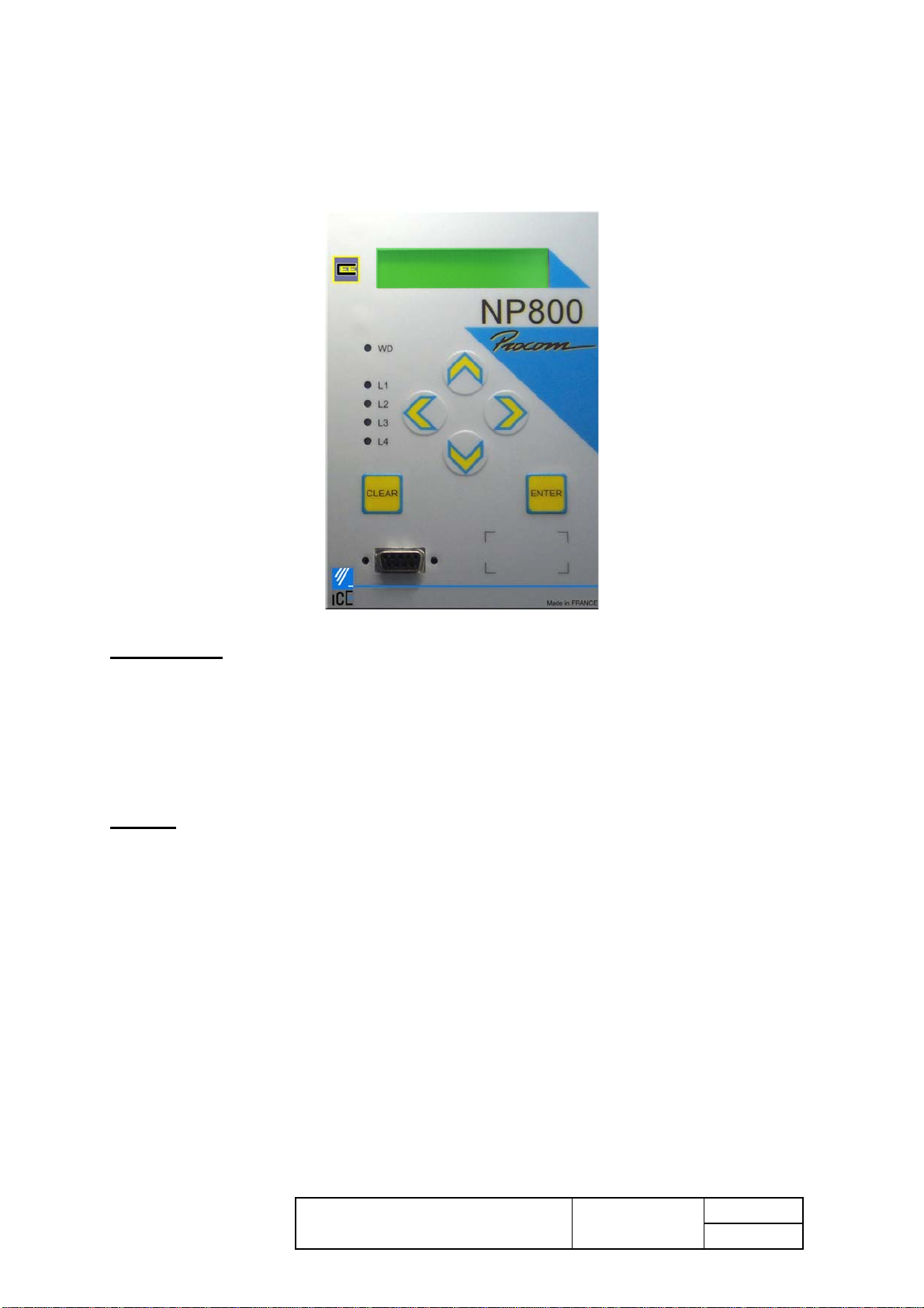
3.1 FRONT PLATE DESCRIPTION...................................................................................................................... 6
3.2 OUTPUT RELAYS ASSIGNMENTS .............................................................................................................. 7
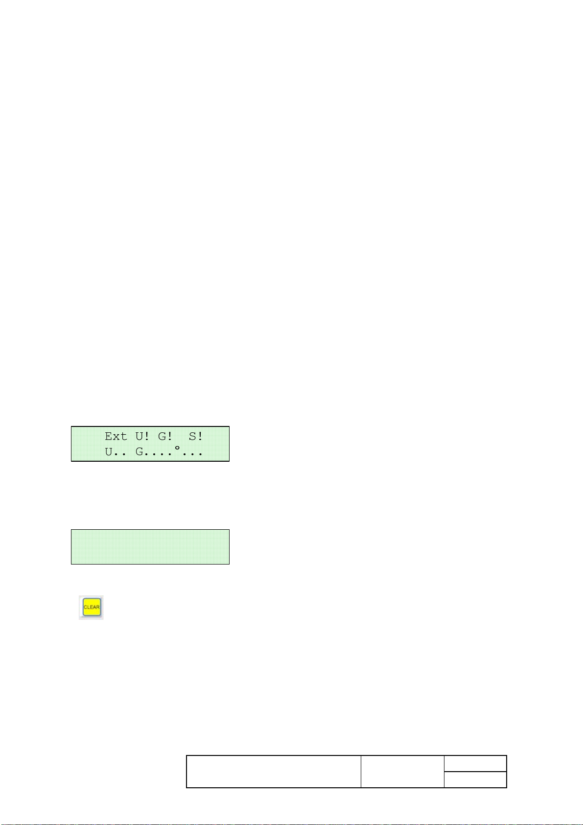
3.3 DEFAULT DISPLAY ................................................................................................................................... 7
3.4 PRESENCE OF EVENT OR FAULT ................................................................................................................ 7
4. GENERAL INFORMATION ON THE USE OF THE MENUS ____________________________ 8
4.1 SETTING MODE (IN /OUT)........................................................................................................................ 8
4.2 MODIFICATION OF A PARAMETER............................................................................................................. 8
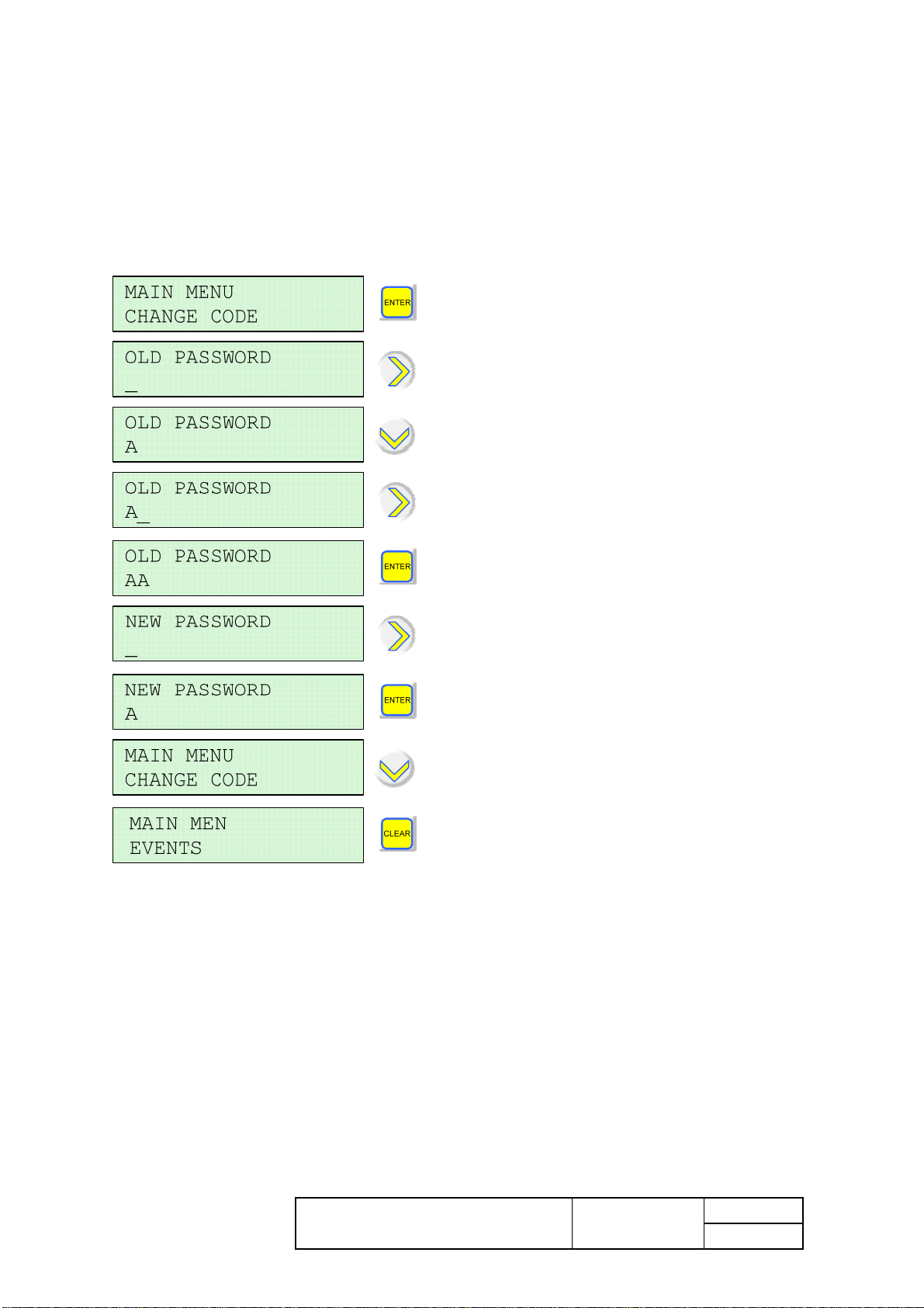
4.3 CHANGING PASSWORD ............................................................................................................................ 9
5. MENU LIST _____________________________________________________________________ 10
5.1 ACCESS TO MAIN MENU ......................................................................................................................... 10
5.2 MEASUREMENTS MENU.......................................................................................................................... 11
5.3 SETTINGS MENU .................................................................................................................................... 12
5.4 DISTURBANCE MENU.............................................................................................................................. 15
5.5 OPERATION MENU.................................................................................................................................. 16
5.6 MODBUS®COMMUNICATION MENU (IF OPTION AVAILABLE) ................................................................ 17
5.7 CHANGING PASSWORD MENU ................................................................................................................ 17
5.8 INFORMATION MENU .............................................................................................................................. 18
6. CONTENT OF AN EVENT_________________________________________________________ 19
6.1 GENERATED EVENTS BY DIGITAL INPUT ACTIVATION............................................................................ 19
6.2 OTHER EVENTS ...................................................................................................................................... 20
6.3 ACKNOWLEDGEMENT OF EVENTS .......................................................................................................... 21
6.4 DISPLAYING OF THE LAST RECORDED EVENTS. ...................................................................................... 21
7. NPRG 860 / NPRG870 CONNECTIONS ______________________________________________ 22
7.1 TERMINALS BLOCKS DESCRIPTION ......................................................................................................... 22
7.2 EXTERNAL CONNECTIONS ...................................................................................................................... 23
7.3 CONNECTION DIAGRAMS REFERENCE..................................................................................................... 23
7.4 CONNECTION OF THE MODBUS RS485 COMMUNICATION ...................................................................... 24

This document is the sole property of
ICE. No duplication nor release to third
party is allowed without prior
authorization.
NPRG 870 – NPRG 860
User’s Guide Date : 09/2010
Edition :13/06/2017 Sheet : 3
Issue : D
1. Safety instructions
For your safety, we recommend you to read the following information carefully. They have
the aim of specifying the precautions essential to the good installation and the correct
operation of the products.
1.1 Documentation
Following documentations are available for the products of range NP800:
General presentation of NP800 Range.
Application Guide of NP800 Range.
User’s Guide of the SMARTsoft Setting Software
User’s Guide (by type of product)
First Handling Guide (by type of product)
Diagram for each relays.
We advise you to read them before any handling.
1.2 Connection of the NP800 range
The terminal blocks of the Automatic Synchronizer are studied to ensure the safety of the
people during the operation of the products.
During installation, commissioning or maintenance, they can however present high voltages
and possibly a thermal heating. Consequently, the following precautions must be respected:
Connection of the terminal blocks at installation must be carried out after having
ensured of the absence of any voltage
Their access during operation must be carried out through adequate means ensuring
as well electric as thermal insulation
The connection of the earth at the back of the relays must imperatively be done with
mean of a 2.5 mm² wire.
Before powering the Automatic Synchronizer, it will be necessary to check in particular:
The value of the voltage rating of the auxiliary supply and its polarization
The good realization of connections
Integrity of the connection to the earth.
1.3 On load withdrawal
It is formally misadvised to withdraw the connectors under voltage or on load.
1.4 Removal and destruction
The Automatic Synchronizer should in no case be opened by the User. During their removal,
they must be completely isolated from any external polarity and capacitors must be
discharged by connecting their external terminals to the earth.
The destruction of the Automatic Synchronizer will have to be carried out in accordance with
the legislation in force, in particular in compliance with the environment and safety
requirements.

This document is the sole property of
ICE. No duplication nor release to third
party is allowed without prior
authorization.
NPRG 870 – NPRG 860
User’s Guide Date : 09/2010
Edition :13/06/2017 Sheet : 4
Issue : D
2. Regulation and operation functions - Local functionalities
2.1 ANSI Functions
Regulation of speed "NPRG 860 - NPRG 870" - ANSI 90.
Regulation of voltage “NPRG 870” - ANSI 90 + management of 4 generators.
Synchrocheck “NPRG860 - NPRG 870” - ANSI 25 + management of 4 generators.
2.2 Operation functions NPRG 860
Calculation of the paralleling circuit breaker closing time for anticipation
Dead Busbar paralleling
Shift phase of the VT “Generator” measurements
Electrical quantities measurements :
Phase voltage UGE, UBB
Frequency FGE, FBB
Difference of voltage U (UGE – UBB)
Angular variation
Compensated angular variation
Variation of frequency F (FGE – FBB)
Acceleration / Deceleration (Hz/s)
Paralleling CB closing time (ms)
anticipation (°)
Storage of the last 250 events and saving of the last 200 events on lack of the auxiliary
supply
Storage of four disturbance recordings, according to COMTRADE®standard
2.3 Operation functions NPRG 870
Idem NPRG860
Four settings groups for the management of 4 Generators
2.4 User’s functions available
In local mode, the following functions are available:
Choice of language
Displaying of the Automatic synchroniser identification
Displaying of the paralleling values
Displaying of each memorized value: measurements
Displaying of each events recorded
Displaying the status of each inputs / Outputs
Change the setting of the disturbance pre-time
Change the settings of the Modbus®communication (speed, format, …)
Adjustment of LCD contrast
NPRG860 – NPRG870 Software Version.

This document is the sole property of
ICE. No duplication nor release to third
party is allowed without prior
authorization.
NPRG 870 – NPRG 860
User’s Guide Date : 09/2010
Edition :13/06/2017 Sheet : 5
Issue : D
2.5 User’s functions not available
In local mode, the following functions are not available:
Enabled or disabled the functions
Setting of each function and primary/secondary values for each setting groups (for each
tables (Generator) NPRG870 version only).
Commissioning tests: LCD display, adjustment of contrast, LEDs
Commissioning tests: relays, wiring and synchroscope
Disturbance viewer
The functions not available locally are however accessible thanks to the settings software.

This document is the sole property of
ICE. No duplication nor release to third
party is allowed without prior
authorization.
NPRG 870 – NPRG 860
User’s Guide Date : 09/2010
Edition :13/06/2017 Sheet : 6
Issue : D
3. First use
3.1 Front plate description
Ext Uok Gok St
U-1 G+.50 °-17
Display of NPRG870 version
LEDs display:
WD: Watchdog
L1: AUTO mode enabled
L2: Synchrocheck mode enabled
L3: Slip OK
L4: Paralleling Order
Display:
When one of the three conditions is filled and that stability is correct, the following message
appears on the two lines of the display:
UG°:ok (ΔU ok) else U!
UG°:ok (ΔF ok) else G!
UG°:00 (Δφ ok) else °+50 for gap +50°
St : (Stability ok) else S!
Uok Gok St (the first two conditions are met with a correct stability)
°00 (gap of correct phase)
Indication of the measurement mode INT or EXT
The value of the difference in voltage, slip and phase shift is indicated:
U+/-x in % G+/-x,xx in Hz °+/-xx in degree °

This document is the sole property of
ICE. No duplication nor release to third
party is allowed without prior
authorization.
NPRG 870 – NPRG 860
User’s Guide Date : 09/2010
Edition :13/06/2017 Sheet : 7
Issue : D
3.2 Output Relays Assignments
The Automatic Synchronizer device with his initial configuration, NPRG860, provides: 3
output relays + 1 watchdog relay. In extended version, NPRG870 version, this one provides
7 output relays + 1 watchdog relay.
The assignment cannot be modified.
WD: Watchdog
Relay A: +f order
Relay B: - f order
Relay C: Paralleling order
The following relays are available only with the NPRG 870 version only.
Relay D: Generator selection fault
Relay E: +U order
Relay F: -U order
Relay G: Paralleling of dead bus line enable
When powering the relay with the auxiliary supply, the displays below can appear. The
advised actions allow reaching the beginning of the setting of the Automatic synchronizer.
3.3 Default display
Without event and measurements, the relay displays the different status of measurements:
3.4 Presence of event or fault
When event appears, message indicates the type:
INVALID SELECT A
14/01 10:21:33 R
This last event will disappear by acknowledgment of the fault by pressing the CLEAR key
or automatically after a time delay of 20s.

This document is the sole property of
ICE. No duplication nor release to third
party is allowed without prior
authorization.
NPRG 870 – NPRG 860
User’s Guide Date : 09/2010
Edition :13/06/2017 Sheet : 8
Issue : D
4. General information on the use of the menus
All parameters can be accessed for reading. On the other hand, parameters are write-
protected by an access code requested on the first modification.
4.1 Setting mode (In / Out)
Press any key except CLEAR to enter in setting mode.
If no parameter has been modified, exit the mode by pressing the CLEAR key:
Ext U! G! S!
U.. G....°... MAIN MENU
MEASUREMENT
ENTER CLEAR
If a parameter has been modified, confirm the exit from settings mode:
Without any operation, return to operation mode is carried out automatically after 5 minutes.
4.2 Modification of a parameter
Use the " " and " " keys to select a menu then press the ENTER key to access the first
parameter.
Use the " " and " " keys to access the various parameters in the menu:
Use the and keys to modify the parameter.
You must confirm your change using the ENTER key after each parameter modification. The
first modification imposes to enter the access code. After storing the new parameter value,
next parameter is displayed:
Press the CLEAR and keys change menu
When you’re in a sub-menu, it’s possible to exit it from anywhere by pressing the CLEAR
key.

This document is the sole property of
ICE. No duplication nor release to third
party is allowed without prior
authorization.
NPRG 870 – NPRG 860
User’s Guide Date : 09/2010
Edition :13/06/2017 Sheet : 9
Issue : D
4.3 Changing Password
On first modification of a parameter, the software requests the access code.
The factory-programmed code is “ICE1".
To enter your own personalised code, use the "CHANGE CODE" menu. The code can be
composed from one up to four alphanumeric characters.
The following example shows how to replace code "AA" with “A":
In case of loss of the code, contact us to obtain an emergency password for your
configuration.

This document is the sole property of
ICE. No duplication nor release to third
party is allowed without prior
authorization.
NPRG 870 – NPRG 860
User’s Guide Date : 09/2010
Edition :13/06/2017 Sheet : 10
Issue : D
5. Menu list
5.1 Access to main menu
The following menus enable setting of the available functions. Each one allows access to the
setting parameters and ensures their coherence.
Access to main menu by
pressing any key.
Press on CLEAR key
to leave the parameter
setting mode
MAIN MENU
MEASUREMENT
Measurements carried out in
real-time by the Automatic
Synchronizer device
Use “ENTER” to select
a menu.
Parameters of the NPRG 860 or NPRG870.
Parameters of the disturbance recording.
Operating parameters to be defined at commissioning.
MENU PRINCIPAL
MODBUS COM.
Configuration of the Modbus®
RS485 communication option (if option available)
Change of the access code.
Last 250 events can be detailed in this menu.
Information about device.
When you’re in a sub-menu, it’s possible to exit it from anywhere by pressing the CLEAR
key.

This document is the sole property of
ICE. No duplication nor release to third
party is allowed without prior
authorization.
NPRG 870 – NPRG 860
User’s Guide Date : 09/2010
Edition :13/06/2017 Sheet : 11
Issue : D
5.2 Measurements menu
This menu displays any real time measurement of the Automatic Synchronizer, the time
stamping and the selected group (NPRG870).
MAIN MENU
MEASUREMENT Measurements available in real-time.
Use the " " and " " keys to access the various
parameters in the “MEASUREMENTS” menu
Generator voltage
measurement. 100 to 500 000 V.
Bus voltage measurement. 100 to 500 000 V.
Generator frequency
measurement. 30 à 70 Hz
Bus Frequency measurement. 30 à 70 Hz
Voltage Difference between
Generator and Bus. -30 000 to +30 000 V
Voltage Difference between
Generator and Bus. -55 to +55 Hz (50Hz)
-65 to +65 Hz (60Hz)
Phase difference between
Generator and Bus. 0 to 360 °
Phase compensated difference
measurement (related to the
measurement of TA). 0 to 360 °
Closing time measurement of
the paralleling CB. 0 to 1 s
Actual anticipation
Measurement. 0 to 360 °
Speed Variation measurement. -10 to +10 Hz/s
Ext U! G! S!
U.. G....°... Measurements default Screen.
Show Digital Input status. I5, I6, I7, I8
(NPRG 870 version
only)

This document is the sole property of
ICE. No duplication nor release to third
party is allowed without prior
authorization.
NPRG 870 – NPRG 860
User’s Guide Date : 09/2010
Edition :13/06/2017 Sheet : 12
Issue : D
Show Output Relays status D, E, F, G
(NPRG 870 version only)
Show selected active
Generator. De 1 to 4 (NPRG 870)
14/01/08
13:38:12 Time & Date.
5.3 Settings Menu
This menu allows reading of all parameters of the NPRG860. The 4 sets of parameters of the
4 groups will be accessible with NPRG870 version.
These settings can be changed only from the setting software.
All the menus below are based on NPRG870 version.
Parameters of the NPRG870.
Use the " " and " " keys to access the various
parameters in the “PARAMETERS” menu
Use the “” and “” keys to access parameters of
GEN1, GEN2, GEN3 or GEN4.
(NPRG 870 only)
Note: The active GEN is indicated by the asterisk.
Bus Rated Voltage. (from
V1.50) 100 to 500 000 V
Generator Rated Voltage.
(from V1.50) 100 to 500 000 V
Rated Voltage of the network.
(until V1.50) 100 to 500 000 V
Primary Voltage of generator
VT. 100 to 500 000 V
VT GEN. – V SEC
100 V GEN1*
Secondary Voltage of
generator VT. 55 to 120 V
VT BUS – V PRIM
10000 V GEN1* Primary Voltage of Bus VT. 100 to 500 000 V
VT BUS – V SEC
100 V GEN1* Secondary Voltage of Bus VT 55 to 120 V

This document is the sole property of
ICE. No duplication nor release to third
party is allowed without prior
authorization.
NPRG 870 – NPRG 860
User’s Guide Date : 09/2010
Edition :13/06/2017 Sheet : 13
Issue : D
Phase shift of the generator 0 to 360 °
Interval between ±U pulses
(only NPRG870) 0 to 250 s
Time of the +U pulse
(only NPRG870) 0 to 0,5 s
Time of the -U pulse
(only NPRG870) 0 to 0,5 s
PULS. WIDTH +U
50 % GEN1*
Pulses width +U
(only NPRG870) 0 to 100 %
Parameter of the
"Proportional" gain for the +U
orders (only NPRG870) 0 to 100
Parameter of the
"Proportional" gain for the -U
orders (only NPRG870) 0 to 100
Interval between ±F pulses 0 to 30 s
Time of the +F pulse 0.1 to 1 s
Minimal pulse Mode Add / Suppress
Time of the -F pulse 0.1 to 1 s
Pulses width +f 0 to 100 %
Parameter of the
"Proportional" gain for the +F
orders 0 to 200
Parameter of the
"Proportional" gain for the -F
orders 0 to 200
Parameter of the "Derived"
gain for the +F orders 0 to 100
Parameter of the "Derived"
gain for the -F orders 0 to 100

This document is the sole property of
ICE. No duplication nor release to third
party is allowed without prior
authorization.
NPRG 870 – NPRG 860
User’s Guide Date : 09/2010
Edition :13/06/2017 Sheet : 14
Issue : D
Black-Start function activation No (out of service) or
Yes (in service)
Waiting Time delay before +F
order for boost. 10 to 200 s
Time pulse of the +F order for
boost. 0,5 to 10 s
Activation of the function
allowing the cut off the ±F
orders after paralleling.
0 (out of service) or
1 (In service)
Positive (+) authorized 1 to 20 °
Negative (-) authorized 1 to 20 °
Minimum operating Voltage of
the generator enabling the
check synchronizing function
[25].
0.50 to 1 Un
Positive (+) Slip Frequency
ΔF allowed. 0.01 to 1.50 Hz
Negative (-) Slip Frequency
ΔF allowed. 0.01 to 1.50 Hz
Positive (+) voltage Difference
ΔU allowed. 0.05 to 0.15 Un
Negative (-) voltage Difference
ΔU allowed. 0.05 to 0.15 Un
Positive Speed Variation
allowed. 0.01 to 0.20 Hz/s
Negative Speed Variation
allowed. 0.01 to 0.20 Hz/s
Maximum anticipatory angle
allowed 1 to 20°
Bus minimum voltage for
allowing the paralleling on Dead
Bus. 0.10 to 0.50 Un
Boost pulsing activation Yes / No

This document is the sole property of
ICE. No duplication nor release to third
party is allowed without prior
authorization.
NPRG 870 – NPRG 860
User’s Guide Date : 09/2010
Edition :13/06/2017 Sheet : 15
Issue : D
Stabilisation time for the
Check Synchro conditions 0.1 to 10 s
Time pulse relay C 0.1 to 10 s
Validation of the too long
paralleling function Yes / No
Time before activate the too
long paralleling function 1 to 3600 s
Positive (>) gap frequency
allowed for paralleling on
Dead Bus. 0.1 to 1.00 Hz
Positive (<) gap frequency
allowed for paralleling on
Dead Bus. 0.1 to 1.00 Hz
Positive (>) gap voltage
authorized for paralleling on
Dead Bus. 0.01 to 0.10 Un
Positive (<) gap voltage
allowed for paralleling on
Dead Bus. 0.01 to 0.10 Un
Monitoring time delay
allowing the activation of the
"paralleling on Dead Bus"
function when all conditions
are correct.
1.0 to 5.0 s
Anticipation Time delay of the
paralleling order to the circuit
breaker 0 to 0.60 s
5.4 Disturbance menu
This menu is used to configure the parameters of the disturbance recording.
MAIN MENU
PERTURBOGRAPHY Settings of disturbance function.
Use "" and "" keys to access into different sub-
menu of « DISTURBANCE »
Pre-time settings. 0 to 170 period (s)

This document is the sole property of
ICE. No duplication nor release to third
party is allowed without prior
authorization.
NPRG 870 – NPRG 860
User’s Guide Date : 09/2010
Edition :13/06/2017 Sheet : 16
Issue : D
5.5 Operation menu
This menu is used to set the parameters of operation function: language choice, LCD
contrast adjustment.
Operation function to be defined during the
commissioning.
Use "" and "" keys to access into different sub-
menu of « OPERATION »
Language choice. French, English,
Spanish, Italian
LCD adjustments. 70 to 255

This document is the sole property of
ICE. No duplication nor release to third
party is allowed without prior
authorization.
NPRG 870 – NPRG 860
User’s Guide Date : 09/2010
Edition :13/06/2017 Sheet : 17
Issue : D
5.6 Modbus® Communication menu (if option available)
This menu is used to define the Modbus® communication parameters: slave number, format,
speed, activity test.
MAIN MENU
MODBUS COM. Modbus® communication function - RS 485.
Use "" and "" keys to access into different sub-
menu of « MODBUS COMMUNIC. »
Slave number. 1 to 255
FORMAT
8b+1p+1s BIN.
Number of bits + parity + bits
of stop + ASCII/Binary format. Binary or ACSII
Speed transmission on
RS485 link.
300, 600, 1200, 1800,
2400, 4800, 9600, 19200,
38400, 57600, 115000
Set the time delay of
reception timeout. 0,10 to 20 s
Set the time delay of activity
timeout. 0,10 to 20 s
Test of the parameter setting
and the wiring of Modbus® Mess.Receiv.com1 or
Mess.Not Received
5.7 Changing Password menu
This menu allows change of code and is described in chapter Changing Password.

This document is the sole property of
ICE. No duplication nor release to third
party is allowed without prior
authorization.
NPRG 870 – NPRG 860
User’s Guide Date : 09/2010
Edition :13/06/2017 Sheet : 18
Issue : D
5.8 Information menu
This menu is used to display information: Substation name, Feeder name, Process version.
MAIN MENU
INFORMATION Information menu.
Use "" and "" keys to navigate into the menu
“INFORMATION”.
NPRG 870
50 Hz Displaying the type of device.
Displaying the process version.
Displaying the Substation name (16 digits / line)
Displaying Feeder number (16 digits / line)
Displaying the serial number

This document is the sole property of
ICE. No duplication nor release to third
party is allowed without prior
authorization.
NPRG 870 – NPRG 860
User’s Guide Date : 09/2010
Edition :13/06/2017 Sheet : 19
Issue : D
6. Content of an event
6.1 Generated events by Digital Input activation
Events are recorded when one of Digital Inputs is activated.
Otherwise, for each type of event, it’s possible to read the detail of them by consulting the
dedicated menu described as follows:
List of the last events available
Use "" and "" keys to access into different
events detail of « EVENTS».
Event’s type:
Starting or Ending of the event.
Dated event: Relative or Synchronous
11/01/08
15:06:42.100
Day / Month / Year
Hour: Minute: Second. Millisecond
Setting group activated during the paralleling.
Generator Voltage value measured during the
paralleling.
Busbars Voltage value measured during the paralleling.
Generator Frequency value measured during the
paralleling.
Busbars Frequency value measured during the
paralleling.
Difference between Generator & Bus voltage values
measured during the paralleling.
Difference between Generator & Bus frequency values
measured during the paralleling.
Difference between Generator & Bus phase values
measured during the paralleling.
SPEED VARIATION
0,18 Hz/s Speed variation value measured during the paralleling.
This manual suits for next models
1
Table of contents