Autocall A4098-5217 User manual

Cautions, Warnings, and Regulatory Information
READ AND SAVE THESE INSTRUCTIONS Follow the instructions in this installation manual. These instructions must be followed to avoid damage to
this product and associated equipment. Product operation and reliability depend upon proper installation.
DO NOT INSTALL ANY AUTOCALL™ PRODUCT THAT APPEARS DAMAGED Upon unpacking your Autocall product, inspect the
contents of the carton for shipping damage. If damage is apparent, immediately file a claim with the carrier and notify an authorized
Autocall product supplier.
ELECTRICAL HAZARD Disconnect electrical field power when making any internal adjustments or repairs. All repairs should be
performed by a representative or an authorized agent of your local Autocall product supplier.
STATIC HAZARD Static electricity can damage components. Handle as follows: Ground yourself before opening or installing
components. Prior to installation, keep components wrapped in anti-static material at all times.
Application Notes
The Wall variants are UL listed for General Signaling only but cannot be used in lieu of UL listed Notification Appliances in the area where they are
listed. The Base variants are not suitable for evacuation notification usage.
Introduction
The Addressable Sounder and Sounder Beacons operate with the 4100ES or 4010ES Fire Alarm Control Panels via their Loop Card's addressable loop
but must not be used with unauthorised third-party equipment. They are available in ceiling and wall mounting variants including an outdoor wall
version. The ceiling mounted variants provide a base for fitting an addressable Fire Detector. Alternatively a blanking cap should be fitted.
Summary of the range
Product Details
Base variant
A4098-5217 Addressable Base Sounder
A4098-5220 Addressable Base Sounder Beacon
Wall variant
A4906-5213 Addressable Wall Sounder Beacon White
A4906-5214 Addressable Wall Sounder Beacon Red
A4906-5215 Addressable Wall Sounder Beacon Weatherproof
Accessories
A4905-5201 Blanking Cap for Sounder Bases
A4905-5202 Conduit Adaptor for Sounder Bases
A4905-5203 Shallow Surface Back Box for Indoor Wall Sounder Red
A4905-5204 Shallow Surface Back Box for Indoor Wall Sounder White
A4905-5205 Flush Backbox Adaptor for Indoor Wall Sounder
579-1317AC Rev B
Sounder and Sounder Beacon Installation Instructions
*05791317ACB*
Product Details
A4905-5206 Deep Surface Back Box for Indoor Wall Sounder Red
A4905-5207 Deep Surface Back Box for Indoor Wall Sounder White
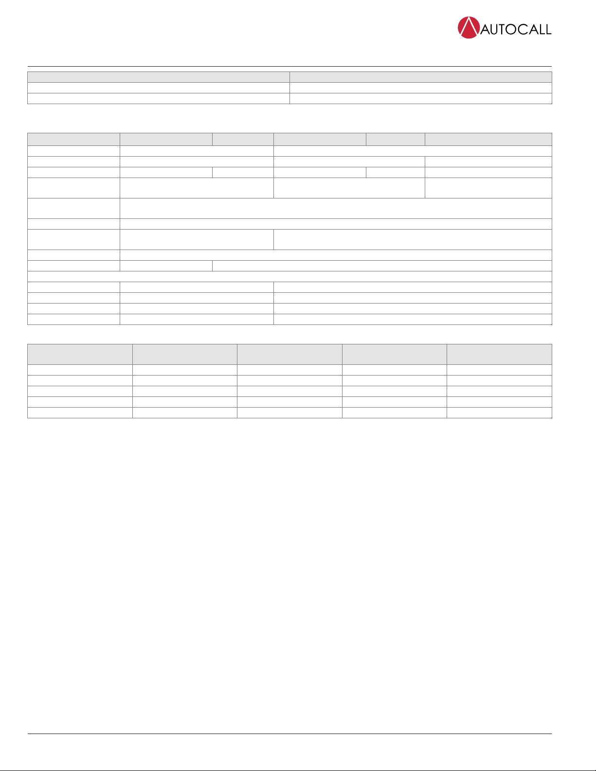
General Information
A4098-5217 A4098-5220 A4906-5213 A4906-5214 A4906-5215
Mounting orientation Ceiling Wall
Indoor/Outdoor Indoor Indoor Outdoor
Weight (g) 146 g (5.15 oz) 154 g (5.4 oz) 194 g (6.8 oz) 194 g (6.8 oz) 372 g (13.1 oz)
Operating
temperature (°C)
0°C to 70°C (-32°F to +158°F) 0°C to 49°C (-32°F to 120°F) -25°C to +70°C (-13°F to +158°F)
Storage temperature
(°C)
-25°C to +70°C (-13°F to +158°F)
Humidity Up to 95% non-condensing
Sounder volume
settings
4 2
Isolator Yes
Beacon flash rates - 0.5 Hz and 1 Hz
Typical Sounder output at 1 metre (3.28 feet)
High volume 90 dBA 100dBA
Mid High volume 80 dBA -
Mid Low volume 70 dBA -
Low volume 60 dBA 90 dBA
Loop loading (A4098-525X series addressable detector fitted to the base variants)
Sounder volume Beacon flash rate (if
applicable)
Wall sounder beacon Base sounder Base sounder beacon
OFF OFF 0.35 mA 0.88 mA 0.88 mA
LOW OFF 3.2 mA 3.0 mA 3.0 mA
HIGH OFF 8.6 mA 4.8 mA 4.8 mA
HIGH 0.5 Hz 11.2 mA - 8.0 mA
HIGH 1 Hz 13.6 mA - 9.6 mA
Note: Please refer to the loop loading calculator for these units.
Address programming and configuration
Default address = 255. Set the address before installation using either the 801AP service tool with its ancillary lead. Remove the front cover to access
the programming port on wall devices. The 850EMT tool can be used to set the tone, flash rate and volume level. Refer to the document 125.515.058:
850 Engineering Tool User Manual for details.
page 2 579-1317AC Rev B
Sounder and Sounder Beacon Installation Instructions
Installation
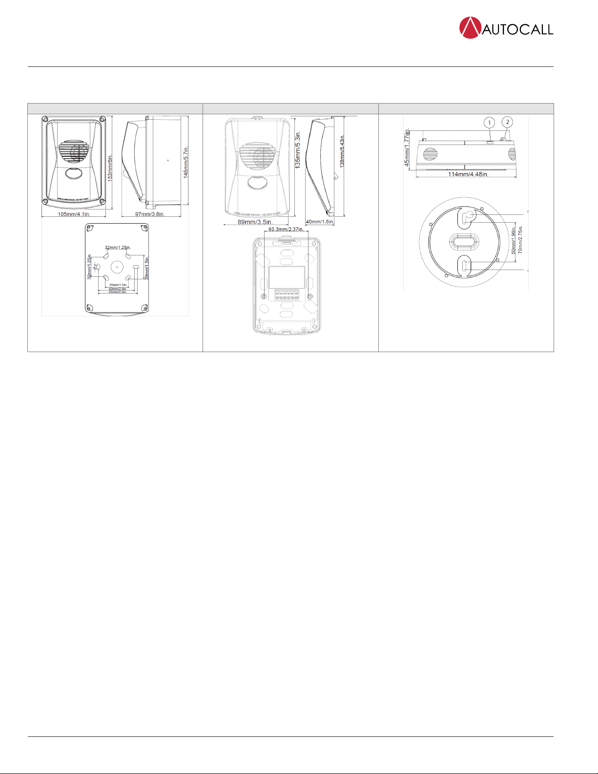
Dimensions
Weatherproof wall units Indoor wall units Base units
Figure 1: Sounder Beacon
Figure 2: Sounder Beacon
Figure 3: Base unit
1. Temporary park plunger and indicator (yellow)
for short circuit isolator.
2. Address flag holder.
page 3 579-1317AC Rev B
Sounder and Sounder Beacon Installation Instructions
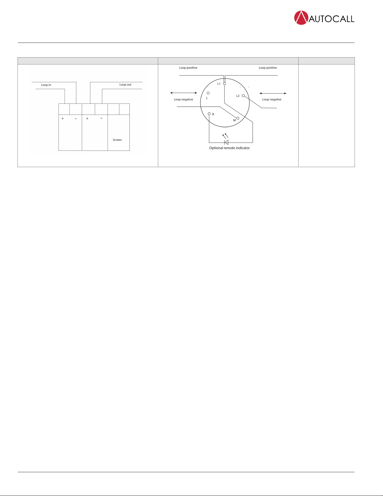
Wiring
Wall variant wiring Base variant wiring Contact and Function
Figure 4: Wall variant wiring
Figure 5: Base variant wiring
L: Not used
L1: Positive line in and
out
L2: Negative line
(isolator in and out)
M: Negative line (isolator
in or out)
R: Remote LED out,
wired only if a remote
indicator is required.
Wiring notes
• All wiring must comply with local installation regulations and local fire system design requirements.
• Ensure all conductors are free of earths.
• Verify correct wiring and wiring polarity before connecting the devices to the addressable loop.
• Cables are to be selected in accordance with local standards, and with document 17A-02-D: MX Range of Addressable Controllers.
page 4 579-1317AC Rev B
Sounder and Sounder Beacon Installation Instructions
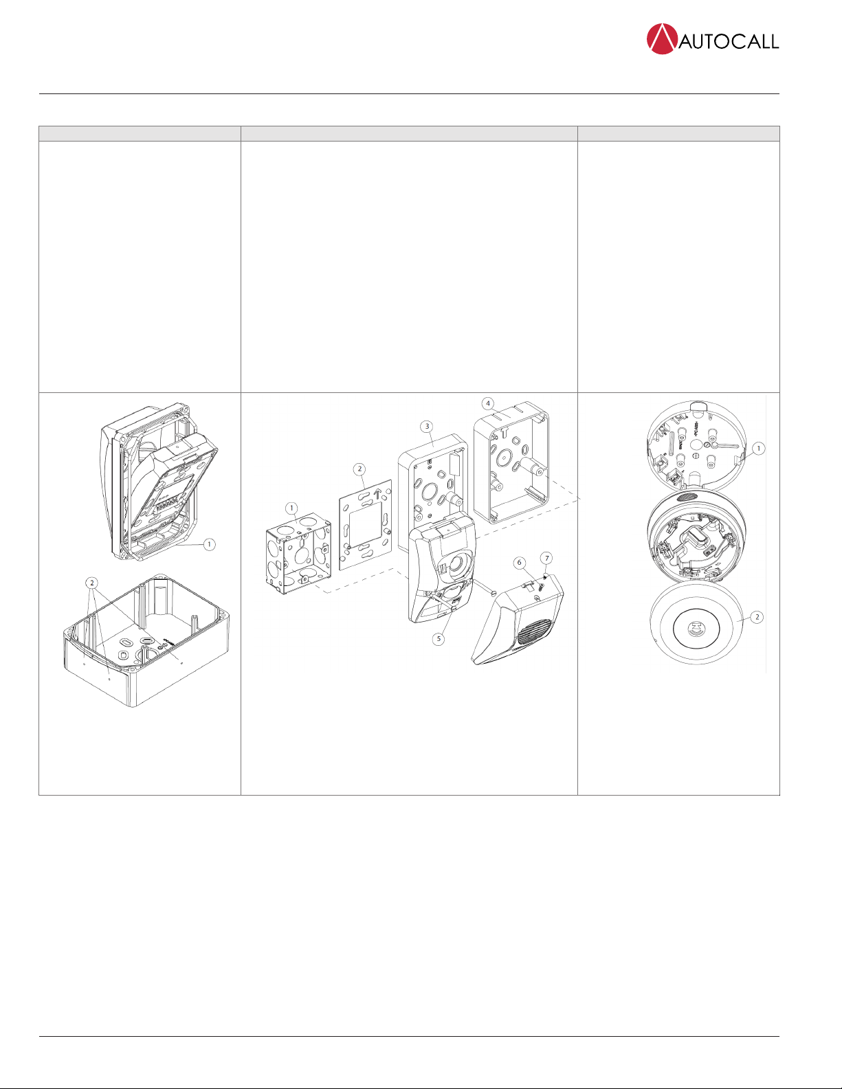
Mounting and fixing instructions
Weatherproof wall units Indoor wall units Base units
These units are supplied with their own
back box and special front cover. A
sealing ring is supplied fitted on this
front cover. See item 1 in Figure 6.
1. Fix the back box to the wall. Drill
positions for glands on the top,
bottom, and sides, see item 2 in
Figure 6.
2. Slide the wall unit into place in the
front cover as shown and then push
down until it clips in.
3. Secure the front cover (including the
wall unit) to the back box with the
four supplied screws (M3.5 hex head)
using the supplied Allen key.
Note: To maintain the IP rating, use
suitably rated cable glands and sealant
as required.
1. Unclip the front cover from the wall unit using the screwdriver
slot on the top. The front cover is hinged at the bottom of the
unit.
2. Use the two supplied screws to either fix the unit to the optional
back box (with knockouts for conduit connections) or to the
optional adaptor plate or to a back box with suitable mating
fixings.
3. Refit the front cover, engaging the clips on the bottom first.
4. Secure the front cover with either the supplied self-tapping
screw or nylon plug.
Note: If using the adaptor plate, a suitable recess is required for
the connector block protruding from the rear of the wall unit.
These units either fit directly to the
ceiling or to an optional ceiling adaptor.
The ceiling mounted variants provide
a base for fitting a fire detector.
Alternatively, a blanking cap is fitted. See
Figure 8. See Figure 10 for fitting the
locking pin. To remove a detector from a
base with a locking pin, complete these
steps:
1. Insert a suitable tool into the access
hole to depress the locking pin in the
detector cover.
2. Rotate the detector to remove.
These units can be used with the Ceiling
Tile Adapter (CTA) kit (517.050.060) by
using the CTA Adaptor Plate, CTA-AP
(517.050.058). Use the knock outs for
the cabling as required.
Figure 6: Fitting
weatherproof wall units
Figure 7: Indoor wall units
1. Single gang flush back box
2. A-BOX
3. S-BOX
4. D-BOX
5. M3.5 screw x 2
6. Self-tapping screw
7. Nylon plug
Figure 8: Fitting base units
1. A-CON
2. B-CAP
page 5 579-1317AC Rev B
Sounder and Sounder Beacon Installation Instructions

Wall units Base units
Figure 9: Checking the gasket
1. Check that the gasket (item 1) is seated correctly before fitting the front cover.
2. Note the 'v' notch (item 2) on the upper side and gasket retained by the hooks on both sides (item 3).
3. Item 4 is the programming port.
Figure 10: Fitting
the locking pin
579-1317AC Rev B
© 2021 Johnson Controls. All rights reserved. All specifications and other information shown were current as of document revision and are subject to change without notice. Additional listings may be applicable, contact your local Autocall
product supplier for the latest status. Listings and approvals under Tyco Fire & Security GmbH, and the product names listed in this material are marks and/or registered marks. Unauthorized use is strictly prohibited. NFPA 72 and National
Fire Alarm Code are registered trademarks of the National Fire Protection Association (NFPA).
This manual suits for next models
4
Table of contents


