Prospec Electronics JBL MR17 User manual
JBLMR17/17.2/17.3Troubleshooting guide
Prospec Electronics
Note: Please click on highlighted words for links to parts of this document and our website.
1.0. Wiring
2.0. Compatible Accessories
3.0. List of common issues and solutions
3.1. No power
3.2. Intermittent Power
3.3. Buttons/controls not responding or behaving erratically
3.4. Poor reception or no reception
3.5. No audio, speaker audio is unevenly distributed or some speakers not working
3.6. Low audio
3.7. Fluctuating audio
3.8. Moisture in display
3.9 CD player not working
4.0. External Amplifier Issues
5.0. Sirius Issues
6.0. Reset Procedure
7.0. Location of Product and Serial Numbers
8.0 Replacement Options

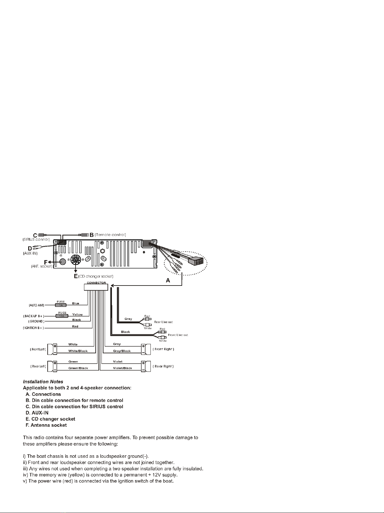
1.0. Wiring - Follow the wiring diagram above
•Wire Harness
•The red ignition B+ wire is designed as the trigger to turn the radio on. It recommended that this wire is connected to an
on/off switch for purposes of lowering the current draw on the battery while the radio is not in use. The yellow memory
wire needs constant current to remember presets and other settings.
•Both red ACC and yellow battery wires must be connected to 12V+ for the radio to turn on.
•Ground (black) must be connected to a good 12V- source. Best source is directly to the battery or bus bar closest the
battery.
•Speaker wires must be installed to the individual speaker’s terminals as labeled, positive and negative, respectively. Never
combine any speaker wires as this will cause permanent damage to the radio’s output IC. Tape off any unused speaker
wires individually to prevent accidental shorting which can also harm the output IC.
•Blue wire, labeled as “AUTO ANT”, is a 12V+ remote lead powered up when the radio is turned on. This lead is used as the
remote turn on for additional electronics such as an amplified antenna or external amplifier. Depending upon the
specifications of some amplifiers or amplified subwoofers, using this lead to power on more than one may not be possible
and the addition of a 12V relay may be necessary.
•Antenna- must be installed in the supplied slot located at the heat sink. This location is labeled as F in the wiring diagram.
•Remote control cables –13-pin DIN style cable/connector designed for wired remotes. See compatible products.
•AUX input –female RCA connectors for use of various input devices with AUX output capabilities. The stereo will NOT
control any of these devices but audio from these devices can be heard through the stereo while in AUX mode. Some of
the devices, with the appropriate adapter, can include TVs, CD changers, MP3 players, and other portable media devices.
See compatible products for adapters we offer.
•Line Outs- used for an amplifier input to the radio. Allows the amp to play what the radio is playing.
•Sirius Control- used for Sirius tuner for Sirius radio. Without tuner, Sirius will not work on MR17. See compatibility for
necessary tuner.
2.0. Compatible Accessories- See our website for the following add on accessories
SEAMINI
JBLREM20 –DIN-AMP adapter required
SEAMINI or SEAMINI2 –RCA to 3.5mm head phone jack
JBLREM21 –DIN-AMP adapter required
JBLREM25 –DIN-AMP adapter required
JBLREM30 –DIN-AMP adapter required
Sirius- MR17/17.2 needs Sirius 2.5 OR Sirius 2.5 to SCC1 Tuner Converter and SCC1 tuner. MR17.3 needs SCC1 tuner. Not
sold on our website.
JBLREM35- we no longer sell
JBLREM40- DIN-AMP adapter required
JBLREM45
JBLMC19
JBLMC18/18.3-we no longer sell
MIL-BTREC
MCDC100-we no longer sell
MCDC100.2-we no longer sell
Any Single din cover
Remote adapter and extensions
REX20-13 remote extension –fits REM35 and REM45, MC-19 and REXW-13.2
REXW-13.2–three way splitter for REM35/45, MC-19 and REX20-13

3.0. List of common issues and solutions
3.1 No power
•Check each button on the control pad for sticking. Under normal conditions, a faint click is heard upon pressing
each button. If a button is stuck or does not click, please replace the faceplate or the radio itself. See replacement
options in 8.0.
•Ensure red and yellow leads are connected to a good 12V+ source. Both must have power for the radio to turn on.
•Ensure black ground wire is connected to a good reliable ground source.
•Open the fuse holder and check the fuses. Note, while in most situations, a bad fuse can be spotted visually, this
may not always be the case. The best method would be to use a multi-meter or a test light. Replace with 10amp
fuse.
•While the fuse holders are open, inspect the fuses and terminals for rust and corrosion.
•Ensure the battery/power supply is putting out at least 12V while under load. The radio requires at least 11.5V to
operate normally.
•Check all connections for corrosion, looseness, or other condition that can produce a bad ground. Corrosion or
terminal looseness is the leading cause for most grounding issues and can cause excessive heat resulting in melting
wires or terminals.
•Unplug any additional remotes, remote adapters, or extensions from the back of the stereo to determine if the
root cause of the problem is actually with another component.
3.2 Intermittent Power
3.2.1 Powers on and off constantly
Check voltage under load. At least 11.5V must be maintained consistently to operate the radio
normally.
If voltage cannot be maintained, load test the battery or power supply.
Check all connections for corrosion, looseness, or other condition that can produce a bad ground.
3.2.2 Powers off and on while the vehicle is moving
Inspect all connections including the radio’s harness for looseness. Wriggle connections while the radio
is operating to produce the symptom and narrow down the loose connection.
3.3 Buttons/controls not responding or behaving erratically
3.3.1 Symptoms
•Stations scanning continuously
•Run away volume
•Controls frozen
3.3.2 Troubleshooting
3.3.2.1 MR17, MR17.2, MR17.3
•Check each button on the control pad for sticking. Under normal conditions, a faint click is heard upon
pressing each button. This includes the volume and tuning knobs which should also click when
presses. If any button does not click, contact us via email to purchase a faceplate if any are in stock or
replace radio. See 8.0 for replacement options.
•Check for corrosion on faceplate connector. If corrosion, replace radio.
•If some buttons do not work, contact us via email to purchase a faceplate if we have any in stock or
replace radio. See 8.0 for replacement options.
•Detach any additional equipment connected to the radio such as remotes, remote adaptors, and
extensions. If the stereo returns to normal operation, plug one attachment in at a time until the
discovering the defective part.
•Check all remote connections for water intrusion or corrosion. This includes any extensions connected
to the radio or remote. If any connections are corroded, replace the corresponding part. The best
corrective measure to prevent this from happing again is to seal this connection with an adhesive
shrink tube and heat gun. If these materials are not readily available, make sure all connections are
higher than the mounting location of the remote and radio so any water entering these areas does

not follow along the cable and into the connection. Also make sure these connections are in dry areas.
•If equipment is detached and there is still erratic/frozen controls, problem might be with the faceplate.
Try another faceplate.
•If faceplate doesn’t work, email us to see if we have replacement faceplates or replace the radio. See
8.0 for replacement options.
3.3.2.2 Troubleshooting additional remotes, adapters and extensions- see below picture
•JBLREM45 wired remote control
•REX20-13
•REXW-13 and REXW-13.2
JBLREM45 REX20-6 REXW-13.2
3.3.2.2.1 Troubleshooting Recommendations
3.3.2.3.1.1 Follow all normal troubleshooting steps as outline in 3.3.2.1
3.3.2.3.1.2 Addition Steps
•Detach REM45 remote
•Detach REX20-13 extension and REXW from back of stereo
•Plug REM45 or other secondary remote directly into remote harness of MR17/17.3 and
observe results
3.3.2.2.2 Results
3.3.2.2.2.1 System responds normally –replace extension and possibly REXW if equipped.
3.3.2.2.2.2 System still not responding normally
3.3.2.2.2.2.1 Unplug REM45 or secondary remote
If stereo is operating normally, replace remote.
If stereo is still NOT responding, replace stereo.
3.3.2.2.2.3 Unable to determine results of troubleshooting
Replace the extension.
NOTE: IF THERE IS ANY CONFUSION ON THIS PROCESS, SEE ERRATIC CONTROLS TROUBLESHOOTING VIDEO FOR GENERAL
TROUBLESHOOTING PROCESS.

3.4 Poor reception or no reception
3.4.1 For an amplified antenna
•Ensure the antenna is connected to power and ground according to manufacturer’s instructions.
•The antenna wire should never be coiled or wound up.
•Check proximity of radio, speakers and antenna to gages, GPS equipment, depth finders, LED lighting, or
any other source of Radio Frequency Interference (RFI) and Electronic Magnetic Interference (EMI).
3.4.2 For all other antennas
•Inspect the antenna for torn wires.
•The antenna wire should never be coiled or wound up.
•Check proximity of radio, speakers and antenna to gages, GPS equipment, depth finders, LED lighting, or
any other source of Radio Frequency Interference (RFI) and Electronic Magnetic Interference (EMI).
3.4.3 LED lighting causes low FM/AM audio or poor reception
•Never bundle the power source wires of the LED lighting to the power wires of the radio or any of
the controllers or speaker leads.
•If needed, the LED power wires and radio power wires should intersect at a 90 degree angle.
•The radio’s antenna must be as far away from the LED lights and power source as possible
•The radio’s speakers also must be as far away from the LED lights as possible.
•If all fails, upgrade the LED lighting to a brand that is guaranteed not to emit RF or EMI.
3.5 No audio, speaker audio is unevenly distributed or some speakers not working
•Check Balance settings. To access and adjust these settings, press the SEL button repeatedly until “Balance displays
on the LCD. Use the volume buttons/knob to adjust. Center the adjustment between left/right. Press the volume
knob again to access the Fader control and repeat the adjustment steps.
•Check speaker connections. Ensure each speaker wire is routed to the appropriate speaker terminal for which it is
intended. Out of phase speakers can have a lower sound that the other speaker which are wired correctly.
•Inspect all speaker wires for exposed wire and tape up as necessary. Make sure they cannot ground to one another
or make contact with any other potential power source or ground. NEVER combine speaker wires.
•If some speakers are working but others are not and the above methods do not help, swap the known working
speakers with the ones that are not working. This will help determine any defective speakers.
•If an external amplifier is connected to the radio and the inoperative speakers are connected via that amplifier, the
amplifier is most likely at fault. Verify the remote lead on the amplifier is connected and has 12V+. Usually
amplifiers are equipped with an LED indicator –see the amplifiers installation guide for specific information.
•If still no audio and the above methods yield nothing, replace the radio. See 8.0 for replacement options.
3.6 Low audio
3.6.1 Low Audio in any mode
Check speaker specifications –recommended impedance is 4ohm
Check sound enhancements - To access and adjust these settings, press the SEL button until BASS is
displayed on the LCD. Use the volume buttons to adjust. Press the SEL button again to access treble. To
access the IEQ feature, press and hold the SEL button (Volume knob) for three seconds then quick press the
SEL button/ turn the volume knob until “DSP” displays on the LCD. Use the volume adjustment to adjust. To
enhance the bass further, press the LOUD button.
3.6.2 Low Audio in FM Mode - LED lighting can cause low FM/AM audio –see section 3.3.3
3.6.3 Low volume in AUX mode
Adjust the volume level of the input device if equipped.
Ensure the input cables are plugged into the RCA input jacks and not plugged into the RCA low level output
jacks.

3.7 Fluctuating audio or FM signal- Audio level constantly raises and lowers when the engine is started or revved. This
issue is more frequently caused by power fluctuations than radio failure.
Check to ensure ground is good and no corrosion exists at connection points.
Check all power wires for corrosion at connection points.
Check for corrosion at battery terminals, bus terminals, and fuse panel.
If in a boat or another motor vehicle, ensure the recommended plugs are being used the engine. Resistor plugs can
often block unwanted RF signal that can interfere with radio reception.
LED lighting can cause fluctuating FM/AM audio –see section 3.4.3
3.8 Moisture in display
3.8.1 Water seen inside the display after washing the mounting area.
Radio is not designed to withstand pressurized streams of water. When rinsing the radio or around the
radio, a very low pressure spray is recommended.
Recommended that a cover is purchased for the MR17/17.2/17.3 as the MR17/17.2/17.3 is not a
waterproof radio. See our website for cover options.
3.9 CD player won’t work
Check to make sure the transit screws are removed. These are the 2 screws on the top of the radio.
Make sure there is only 1 CD in the mechanism at a time.
Reset the radio by disconnecting the wire harness or hitting the reset buttons mentioned in 6.0.
If nothing else works, replace the radio. See 8.0 for replacement options.
4.0 External Amplifier Issues
4.1 Strong hiss –reduce the input gain on the amplifier until the hiss is reduced to an acceptable level while still
maintaining performance. Note, if both amplifier and stereo output can produce distortion, the input gain is
much higher than it needs to be. In most situations, reduced gain levels will not produce detectable performance
conditions.
4.2 Amplifier volume fluctuates or amplifier turns off and on
Check the grounds to both amplifier as well as radio. Corrosion on any the contacts will reduce the ground.
Check system voltage while operating radio and amplifier. If the voltage fluctuates and drops below 11.5 volts, load
test the battery, check the charging system, and check all power and ground wires and contacts for looseness or
corrosion.
Ground the amplifier’s chassis to the stereo’s chassis.
4.3 Audio is extremely low - check the amplifier’s gain setting and increase if necessary.

5.0 Sirius Issues
MR17/17.2
Check to make sure the Sirius 2.5 tuner is connected to the Sirius port on the MR17/17.2 OR Sirius 2.5 to SCC1
converter is connected to the Sirius port
Make sure the tuner converter is connected to the SCC1 tuner if applicable.
Make sure the Sirius antenna is connected to the Sirius 2.5 OR Sirius SCC1 tuner
Check for bent pins on the male Sirius port. Bent pins will cause Sirius to not function.
Contact Sirius if all of the above is connected. Sirius Box might be faulty.
Note: If Sirius is not connected with the correct tuner and antenna, then the MR17/17.2 will show Sirius, and then skip
over Sirius after a delay of 5-10 seconds.
MR17.3
Check to make sure the SCC1 tuner is connected to the Sirius port on the MR17.3
Make sure the Sirius antenna is connected to the Sirius SCC1 tuner
Check for bent pins on the male Sirius port. Bent pins will cause Sirius to not function.
Contact Sirius if all of the above is connected. Sirius Box might be faulty.
Note: If Sirius is not connected with the correct tuner and antenna, then the MR17.3 will show Sirius, and then skip over
Sirius after a delay of 5-10 seconds.
6.0 Reset Procedure
6.1 Method 1- find the hole in the radio’s front behind the faceplate. Insert a paperclip into the hole until a click is felt
and the radio powers off on its own. Image of hole is shown below. Note: Face will need to be removed for this reset.
6.2 Method 3- unplug the 12 pin connector plug (yellow, red and black wires if plug is not on system) from
power/ground for 30 seconds. Note: all presets and other system settings will be lost.
7.0 Location of Serial Number
The serial number is on a silver sticker on the bottom of the radio. “Serial No.:” indicates the serial number. The serial
number will start with MR17/17.2/17.3 respectively.

8.0 Replacement Options
Note: The following are in order from most compatible to least compatible single din radios that we still manufacture.
•JBLMR145.2 (JBLMR-145)
oHas remote connection, but to use the remotes on the MR17, an AMP-DIN adapter is needed. This
adapter will NOT allow display, so display remotes (like the REM45, MC19 and REM35) will not display
(only push buttons will work).
oIf multiple remotes are on the system, please contact us about an extension that can be made for your
system
oDoes not have Sirius capability
oNote: the MR145.3 will replace the 17, but it does not have a remote connection like the MR145/145.2.
•INFMR180
oHas remote connection, but is only compatible with REM50 and MC20 (REM50 replaces the REM45
directly)
oHas a bigger, water proof face.
oHas 2 remote connections, but anything over that will need a custom made extension.
oHas Bluetooth instead of Sirius
•INFPRV250 with MIL-plate1
oHas remote connection, but is only compatible with REM50 and MC20 (REM50 replaces the REM45
directly)
oHas smaller mounting dimensions, but the Single Din Adapter Plate compensates for this.
oHas 1 remote connection, but anything over that will need a custom made extension.
oHas Bluetooth instead of Sirius
Note: Sirius can be used on Bluetooth capable radios by streaming the Sirius app through the Bluetooth of the radio.
•JBL MR-18.5
oNo remote connections available
oDoes not have Sirius
oHas a bigger, waterproof face
oCan work with MIL-BTREC to have Bluetooth.
General Note: Before plugging in the replacement radio, make sure your wire harness colors match up. If they do not, contact
us via email, as plugging the radio in and giving it power could blow your radio.
This manual suits for next models
2
Table of contents


