Stahl C&S YA90 Series User manual

EN
EN
EN
EN
EN
EN
EN
EN
EN
EN
EN
EN
EN
EN
EN
EN
EN
EN
EN
EN
EN
EN
EN
EN
EN
Operating instructions
Additional languages r-stahl.com
EN
C
S
&
Clifford & Snell
Audio signalling device in
flameproof enclosure version
max. 115 dB(A) at 1 m
Series YA90

2
EN
EN
EN
EN
EN
EN
EN
EN
EN
EN
EN
EN
EN
EN
EN
EN
EN
EN
EN
EN
EN
EN
EN
EN
EN
Audio signalling device in
flameproof enclosure version
max. 115 dB(A) at 1 m
Series YA90
Contents
1 General Information ............................................................................................3
1.1 Manufacturer .......................................................................................................3
1.2 Information regarding the operating instructions .................................................3
1.3 Further documents ..............................................................................................3
1.4 Conformity with standards and regulations .........................................................3
2 Explanation of the symbols .................................................................................3
2.1 Symbols in these operating instructions .............................................................3
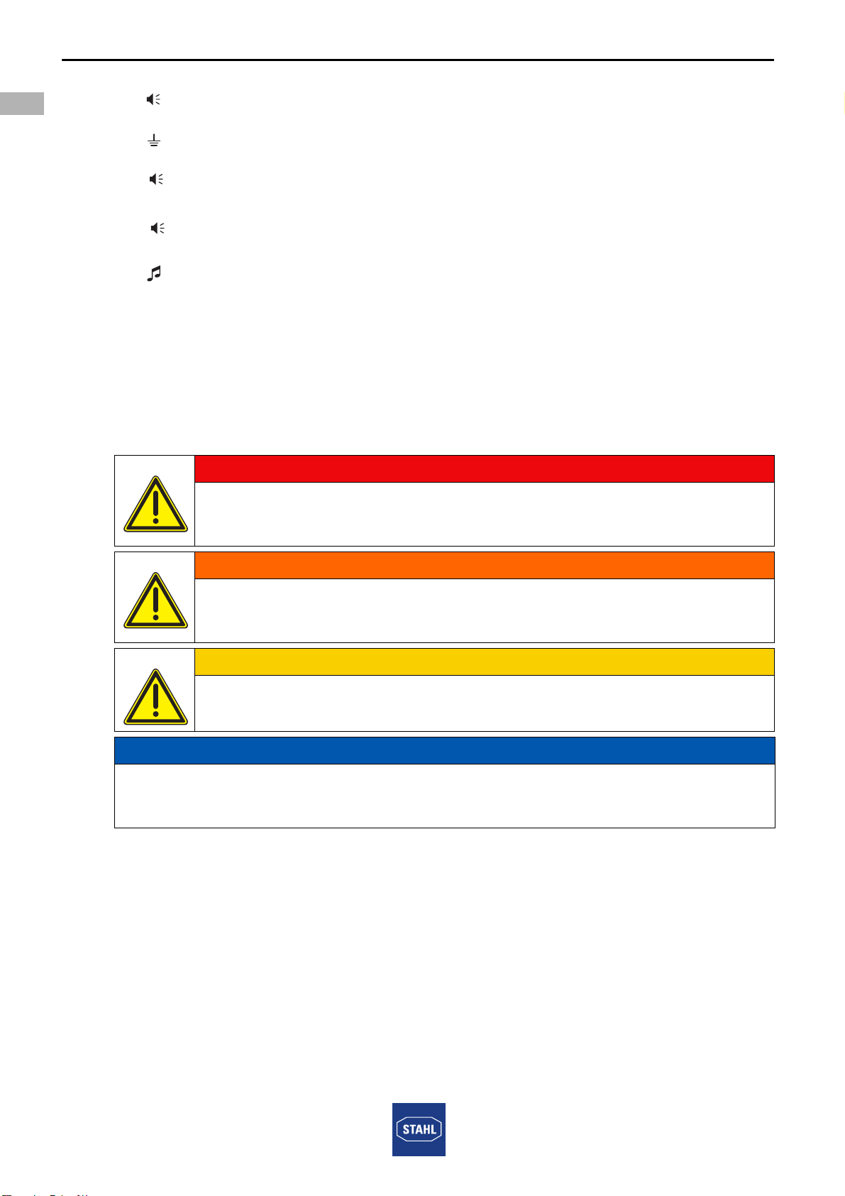
2.2 Warning notes .....................................................................................................4
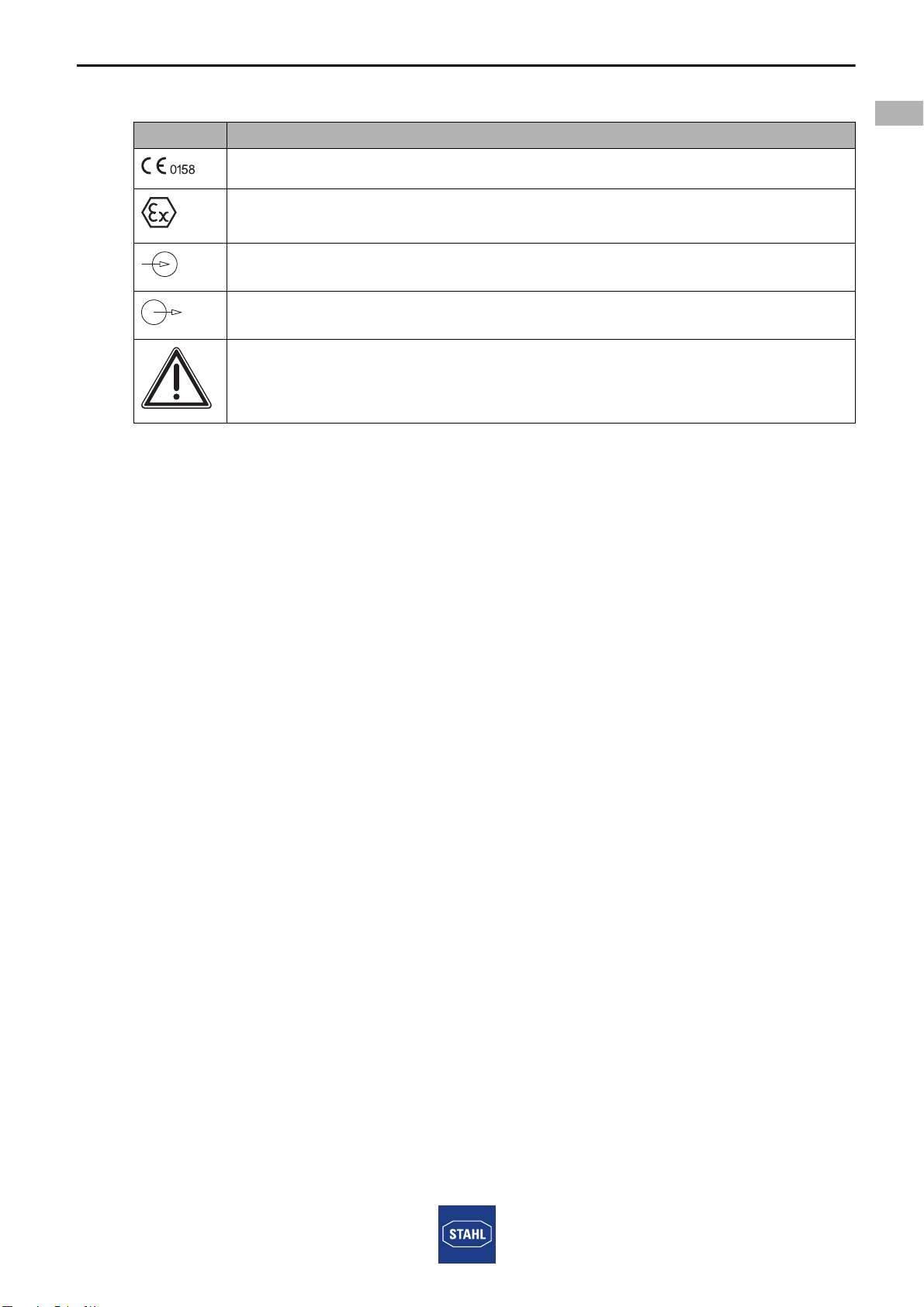
2.3 Symbols on the device ........................................................................................5
3 Safety notes ........................................................................................................5
3.1 Operating instructions storage ............................................................................5
3.2 Personnel qualification ........................................................................................5
3.3 Safe use ..............................................................................................................6
3.4 Modifications and alterations ..............................................................................6
4 Function and device design ................................................................................7
4.1 Function ..............................................................................................................7
5 Technical data .....................................................................................................8
6 Transport and storage .......................................................................................10
7 Mounting and installation ..................................................................................11
7.1 Dimensions / fastening dimensions ..................................................................11
7.2 Mounting / dismounting, operating position ......................................................11
7.3 Installation .........................................................................................................13
8 Commissioning .................................................................................................17
9 Operation ..........................................................................................................18
9.1 Troubleshooting ................................................................................................18
10 Maintenance, Overhaul, Repair ........................................................................18
10.1 Maintenance .....................................................................................................18
10.2 Repair ...............................................................................................................18
10.3 Returning the device .........................................................................................19
11 Cleaning ............................................................................................................19
12 Disposal ............................................................................................................19
13 Accessories and Spare parts ...........................................................................19

223843 / YA9060300010
2019-06-14·BA00·III·en·02
General Information
3
EN
EN
EN
EN
EN
EN
EN
EN
EN
EN
EN
EN
EN
EN
EN
EN
EN
EN
EN
EN
EN
EN
EN
EN
EN
Audio signalling device in
flameproof enclosure version
max. 115 dB(A) at 1 m
Series YA90
1 General Information
1.1 Manufacturer
1.2 Information regarding the operating instructions
ID-No.: 223843 / YA9060300010
Publication Code: 2019-06-14·BA00·III·en·02
The original instructions are the English edition.
They are legally binding in all legal affairs.
1.3 Further documents
• Data sheet
For documents in additional languages, see r-stahl.com.
1.4 Conformity with standards and regulations
See certificates and EU Declaration of Conformity: r-stahl.com.
The device has IECEx approval. For certificate please refer to the IECEx homepage:
http://iecex.iec.ch/
2 Explanation of the symbols
2.1 Symbols in these operating instructions
R. STAHL Schaltgeräte GmbH
Business Unit Lighting & Signalling
Nordstr. 10
99427 Weimar
Germany
R. STAHL Schaltgeräte GmbH
Am Bahnhof 30
74638 Waldenburg
Germany
Phone:
Fax:
Internet:
E-mail:
+49 3643 4324
+49 3643 4221-76
r-stahl.com
Phone:
Fax:
Internet:
E-mail:
+49 7942 943-0
+49 7942 943-4333
r-stahl.com
Symbol Meaning
Tips and recommendations on the use of the device
General danger
Danger due to explosive atmosphere

Explanation of the symbols
4223843 / YA9060300010
2019-06-14·BA00·III·en·02
EN
EN
EN
EN
EN
EN
EN
EN
EN
EN
EN
EN
EN
EN
EN
EN
EN
EN
EN
EN
EN
EN
EN
EN
EN
Audio signalling device in
flameproof enclosure version
max. 115 dB(A) at 1 m
Series YA90
2.2 Warning notes
Warnings must be observed under all circumstances, in order to minimize the risk due to
construction and operation. The warning notes have the following structure:
• Signalling word: DANGER, WARNING, CAUTION, NOTICE
• Type and source of danger/damage
• Consequences of danger
• Taking countermeasures to avoid the danger or damage
= Sounder
= Earth
= Sounder Stage 1
= Sounder Stage 2
= Sounder Tone
DANGER
Danger to persons
Non-compliance with the instruction results in severe or fatal injuries to
persons.
WARNING
Danger to persons
Non-compliance with the instruction can result in severe or fatal injuries to
persons.
CAUTION
Danger to persons
Non-compliance with the instruction can result in light injuries to persons.
NOTICE
Avoiding material damage
Non-compliance with the instruction can result in material damage to the device and / or
its environment.
1
2

223843 / YA9060300010
2019-06-14·BA00·III·en·02
Safety notes
5
EN
EN
EN
EN
EN
EN
EN
EN
EN
EN
EN
EN
EN
EN
EN
EN
EN
EN
EN
EN
EN
EN
EN
EN
EN
Audio signalling device in
flameproof enclosure version
max. 115 dB(A) at 1 m
Series YA90
2.3 Symbols on the device
3 Safety notes
3.1 Operating instructions storage
• Read the operating instructions carefully.
• Store the operating instructions at the mounting location of the device.
• Observe applicable documents and operating instructions of the devices to be
connected.
3.2 Personnel qualification
Qualified specialist personnel are required to perform the tasks described in these
operating instructions. This primarily applies to work in the following areas
• Project engineering
• Mounting/dismounting the device
• (Electrical) Installation
• Commissioning
• Maintenance, repair, cleaning
Specialists who perform these tasks must have a level of knowledge that meets
applicable national standards and regulations.
Additional knowledge is required for tasks in hazardous areas! R. STAHL recommends
having a level of knowledge equal to that described in the following standards:
• IEC/EN 60079-14 (Electrical installations design, selection and construction)
• IEC/EN 60079-17 (Inspection and maintenance of electrical installations)
• IEC/EN 60079-19 (Equipment repair, overhaul and reclamation)
Symbol Meaning
05594E00
CE marking according to the current applicable directive.
02198E00
According to its marking, the device is certified for hazardous areas.
15649E00
Input
15648E00
Output
11048E00
Safety instructions that must always be followed: The respective data must
be noted and/or the safety-related instructions contained in the operating
instructions must be followed for devices with this symbol!

Safety notes
6223843 / YA9060300010
2019-06-14·BA00·III·en·02
EN
EN
EN
EN
EN
EN
EN
EN
EN
EN
EN
EN
EN
EN
EN
EN
EN
EN
EN
EN
EN
EN
EN
EN
EN
Audio signalling device in
flameproof enclosure version
max. 115 dB(A) at 1 m
Series YA90
3.3 Safe use
Before mounting
• Read and observe the safety notes in these operating instructions!
• Ensure that the contents of these operating instructions are fully understood by the
personnel in charge.
• Use the device in accordance with its intended and approved purpose only.
• Always consult with R. STAHL Schaltgeräte GmbH if using the device under operating
conditions which are not covered by the technical data.
• Before installation, make sure that the device is not damaged.
• We cannot be held liable for damage at the device caused by incorrect or unauthorised
use or non-compliance with these operating instructions.
For mounting and installation
• Have mounting and installation performed only by qualified and authorised persons
(see chapter "Qualification of the personnel").
• The device is only to be installed in areas for which it is suited based on its marking.
• During installation and operation, observe the information (characteristic values and
rated operating conditions) on the rating, data and information plates located on the
device.
• Before installation, make sure that the device is not damaged.
Commissioning, maintenance, repair
• Only have commissioning and repairs performed by qualified and authorised persons
(see chapter "Personnel qualification").
• Before commissioning, make sure that the device is not damaged.
• Perform only maintenance work described in these operating instructions.
3.4 Modifications and alterations
DANGER
Explosion hazard due to modifications and alterations to the device!
Non-compliance results in severe or fatal injuries.
• Do not modify or alter the device.
No liability or warranty for damage resulting from modifications and
alterations.

223843 / YA9060300010
2019-06-14·BA00·III·en·02
Function and device design
7
EN
EN
EN
EN
EN
EN
EN
EN
EN
EN
EN
EN
EN
EN
EN
EN
EN
EN
EN
EN
EN
EN
EN
EN
EN
Audio signalling device in
flameproof enclosure version
max. 115 dB(A) at 1 m
Series YA90
4 Function and device design
4.1 Function
Application range
The explosion-protected audio signalling device of series YA90 is intended for use in
hazardous area or in harsh environments.
It can be implemented in hazardous areas according to ATEX / IECEx in Zones 1 and 2
of gas group IIC or in Zones 21 and 22 for dust group IIC as well as in safe areas.
The UL-certified variants can be implemented in areas according to Class I Division 2 for
gas groups A, B, C, D as well as in safe areas.
The device is not intended for continuos use.
DANGER
Explosion hazard due to improper use!
Non-compliance results in severe or fatal injuries.
• Use the device only in accordance with the operating conditions
described in these operating instructions.
• Use the device only for the intended purpose specified in these
operating instructions.

Technical data
8223843 / YA9060300010
2019-06-14·BA00·III·en·02
EN
EN
EN
EN
EN
EN
EN
EN
EN
EN
EN
EN
EN
EN
EN
EN
EN
EN
EN
EN
EN
EN
EN
EN
EN
Audio signalling device in
flameproof enclosure version
max. 115 dB(A) at 1 m
Series YA90
5 Technical data
Explosion Protection
Global (IECEx)
Gas and dust
Europe (ATEX)
Gas and dust
North America (NEC, CEC)
Gas and dust
Certifications and certificates
Certificates IECEx, ATEX, Brazil (INMETRO), China (China Ex), India (PESO),
Korea (KCs), Russia (EAC), USA (UL)
YA90/B versions:
YA90/C versions:
IECEx BAS 08.0062X
IECEx BAS 08.0061X
YA90/B versions: Ex db IIB T6 Ta -60 to +60 ºC Gb
YA90/C versions: Ex db IIC T6 Ta -60 to +60 ºC Gb
YA90/B+C versions: Ex tb IIIC T85 ºC Ta -60 to +60 ºC Db IP66
YA90/B versions:
YA90/C versions:
Baseefa 08 ATEX 0191 X
Baseefa 08 ATEX 0189 X
YA90/B versions: E II 2 G Ex db IIB T6 Ta -60 to +60 ºC Gb
YA90/C versions: E II 2 G Ex db IIC T6 Ta -60 to +60 ºC Gb
YA90/B+C versions: E II 2 D Ex tb IIIC T85 ºC Ta -60 to +60 ºC Db IP66
YA90/B+C versions: E161818
USL: UL 464 / ISA 12.12.01-2007
CNL: CAN/ULC-S525-07, Edition 3 2007 /
CSA C22.2 No. 213
YA90/B versions: USL, CNL - Class I, Div. 2, Groups C and D
Hazardous Locations
Operating temperature -60 to +66 ºC
Audible signal appliance, fire alarm service private
mode
YA90/C versions: USL, CNL - Class I, Div. 2, Groups A, B, C and D
Hazardous Locations
Operating temperature -60 to +66 ºC
Audible signal appliance, fire alarm service private
mode

223843 / YA9060300010
2019-06-14·BA00·III·en·02
Technical data
9
EN
EN
EN
EN
EN
EN
EN
EN
EN
EN
EN
EN
EN
EN
EN
EN
EN
EN
EN
EN
EN
EN
EN
EN
EN
Audio signalling device in
flameproof enclosure version
max. 115 dB(A) at 1 m
Series YA90
Technical Data
Technical data
Product weight AC: 4.6 kg
DC: 4.5 kg
Electrical data
Rated operational
voltage
24 V DC, 48 V DC, 115 V AC and 230 V AC
operational parameters +/-10 %
Rated operational
current
UL calculate the current using RMS Root mean square which gives the
following measurement and is the figure reported on UL variant product labels:
Mechanical data
Material
Enclosure glass-reinforced polyester (GRP)
Horn ABS Flame retardant
Fixings Stainless steel
Cable entries 2 x M20 cable entries equipped with 1 x stopping plug & 1 x dust cover
UL Product variants supplied with 2 x M20 / 1/2’ adaptors
Degree of protection IP66 – BS EN 60529
NEMA 4X – UL 50
Operating temperature range
Ambient temperature ATEX / IECEx variants
cULus & ULC listed
-60 to +66 °C
Max. relative
humidity
95 % at 40 °C
24 V DC 300 mA
48 V DC 160 mA
115 V AC 80 mA
230 V AC 45 mA
24 V DC 500 mA
48 V DC not available UL certified variants
115 V AC 130 mA
230 V AC 90 mA
24 / 48 V DC -60 to +60 °C
115 V AC -40 to +60 °C
230 V AC -40 to +60 °C

Transport and storage
10 223843 / YA9060300010
2019-06-14·BA00·III·en·02
EN
EN
EN
EN
EN
EN
EN
EN
EN
EN
EN
EN
EN
EN
EN
EN
EN
EN
EN
EN
EN
EN
EN
EN
EN
Audio signalling device in
flameproof enclosure version
max. 115 dB(A) at 1 m
Series YA90
For further technical data, see r-stahl.com.
6 Transport and storage
• Transport and store the device only in the original packaging.
• Store the device in a dry place (no condensation) and vibration-free.
• Do not drop the device.
Acoustic data
Volume 115 dB(A) / 1 m
Sound output for products of gas group IIC
Polar diagram
16321E00
Alarm stages 2 stage alarm
Sound selection via DIL switch
Sound signal
selection
32 (see tone table)
All sounders have 32 sound signals. From the 32 sound signals,
any signal may be chosen as the first alert phase and any signal for the second
alert phase.
The volume and current consumption depends on the sound signal selected.
Mounting / Installation
Assembly stainless steel mounting bracket provided,
holes to suit M6, pitch 60 mm
Technical Data
0
330 30
60
300
270
240
210
180
150
120
90
H
V

223843 / YA9060300010
2019-06-14·BA00·III·en·02
Mounting and installation
11
EN
EN
EN
EN
EN
EN
EN
EN
EN
EN
EN
EN
EN
EN
EN
EN
EN
EN
EN
EN
EN
EN
EN
EN
EN
Audio signalling device in
flameproof enclosure version
max. 115 dB(A) at 1 m
Series YA90
7 Mounting and installation
7.1 Dimensions / fastening dimensions
7.2 Mounting / dismounting, operating position
• Mount the device on a flat surface suitable for its weight.
• Direct tone output towards the area to be covered
(see "Technical Data, Polar diagram" chapter).
• Insert the cables using a certified and flameproof cable entry which is suitable for the
gas group.
• Close unused entries using certified, flameproof stopping plugs.
Dimensional drawings (all dimensions in mm [inches]) – Subject to modification
13971E00
DANGER
Explosion hazard due to improper mounting!
Non-compliance results in severe or fatal injuries.
• Only operate the device if it is not damaged.
If the thread is damaged, replace the device immediately.
• Only install the device in a clean and dry operating environment.
• Only mount the device on a wall or on a suitable surface.
• Carefully protect exposed joint surfaces from damage, dust and dirt.
• Install end flanges without applying force (without hammer and tool)
in straight alignment.
• If necessary, fit core end sleeves gas-tight and using a suitable tool.
325 [12,80]
143,50
60 [2,36]
ø210
30 [1,18] 181
[]7,13
[5,65]
[ø 7]8 2
ø 7 [ø 0,28]
ø21 ,7 [ø 0,50]

Mounting and installation
12 223843 / YA9060300010
2019-06-14·BA00·III·en·02
EN
EN
EN
EN
EN
EN
EN
EN
EN
EN
EN
EN
EN
EN
EN
EN
EN
EN
EN
EN
EN
EN
EN
EN
EN
Audio signalling device in
flameproof enclosure version
max. 115 dB(A) at 1 m
Series YA90
7.2.1 Access to the PCB
7.2.2 Reassembly of Enclosure
• Reassemble the unit by inserting the cheese-head screws included in delivery into the
end cap.
• Take care when replacing the PCB.
• Ensure that the seal is placed on the connector.
• Insert the end cap and tighten the screws to a tightening torque of 4 Nm.
16314E00
• Remove 6 screws (1)
(when fastening tighten to 4 Nm)
• Take care when lifting the
end cap (2)
• Place seal (3) on the connector
• Lift the PCB (4) so that the
clamping units are visible.
Use bars to ensure that the
PCB is installed correctly.
1 Screws 3 Seal
2 End cap 4 PCB
• Carefully assemble the device to ensure that the degree of protection
is IP66.
• The cheese-head screws are delivered with Nyltite seals.
• Check the Nyltite seals for damage before the installation.
• Tighten the cheese-head screws to a tightening torque of 3 Nm.
• Use the Nyltite seal a maximum of five times with the tightening torque.
15748E00
4
3
2
1

223843 / YA9060300010
2019-06-14·BA00·III·en·02
Mounting and installation
13
EN
EN
EN
EN
EN
EN
EN
EN
EN
EN
EN
EN
EN
EN
EN
EN
EN
EN
EN
EN
EN
EN
EN
EN
EN
Audio signalling device in
flameproof enclosure version
max. 115 dB(A) at 1 m
Series YA90
7.3 Installation
7.3.1 Electrical Connection
Key components
Cable connection
Parallel connection of several devices
Up to 10 devices can be connected to a supply line parallel.
Circuit diagrams
16315E00 16316E00
Key components YA90 DC Key components YA90 AC
1 Sound selection switch
(see tone table)
3 Terminal blocks
2 Connector for pressure unit
• Approx. 20 cm (8 inches) of electrical line are required for the
connection of the circuit board within the enclosure. This is particularly
important for installing a rigid cable.
• The connection terminal is suitable for cables with a cross section of
2.5 mm2 or 14 to 18 AWG.
Line monitoring for devices with direct voltage
• Through reverse polarity
• By connecting an EOL resistor between 0 V and +V.
The resistance value is defined by the system developer.
Two signal levels for devices with direct voltage
• Through reverse polarity
• By connecting a third electrical line.
Two signal levels for devices with alternating voltage
• By connecting a third electrical line.
3
2
1
1
2
3

Mounting and installation
14 223843 / YA9060300010
2019-06-14·BA00·III·en·02
EN
EN
EN
EN
EN
EN
EN
EN
EN
EN
EN
EN
EN
EN
EN
EN
EN
EN
EN
EN
EN
EN
EN
EN
EN
Audio signalling device in
flameproof enclosure version
max. 115 dB(A) at 1 m
Series YA90
DC versions
AC versions
16317E00 16318E00
Circuit diagram direct voltages
(second stage by means of
third electrical line)
Circuit diagram direct voltages
(second stage using the reverse
polarity)
16322E00
Circuit diagram alternating voltages
= Sounder
= Earth
= Sounder Stage 1
= Sounder Stage 2
= Sounder Tone
1
2
3
4
1
2
3
4
0V
1
+V
+V 2
0V
1+V
+V
2
SW1 SW2
1
2
3
4
1
2
3
4
+V
0V
+V
=2
SW1 SW2
0V
+V
0V
=1
L
SW2
L
LIVE
CONTROL
NEUTRAL
SW1
N
N
L
L
N
N
1 2
1
2

223843 / YA9060300010
2019-06-14·BA00·III·en·02
Mounting and installation
15
EN
EN
EN
EN
EN
EN
EN
EN
EN
EN
EN
EN
EN
EN
EN
EN
EN
EN
EN
EN
EN
EN
EN
EN
EN
Audio signalling device in
flameproof enclosure version
max. 115 dB(A) at 1 m
Series YA90
7.3.2 Earth Connection
16320E00
• The YA90 device must be connected to a good quality earth connection.
• The internal earth connection is the primary connection point. The external connection
is an additional equipotential bonding conductor and is used where local code or
authorities permit or require such a conductor.
7.3.3 Sound Tone Selection
• For signal tone selection and its switch positions refer to the table below.
• Check if the correct switch positions of the selected signal tones have been selected.
Recommendation
• The signal tone selection should be set at the factory or at an approved
factory.
Tone table
Tone
no.
Version Frequency
Sound
selection
switch
12345
(ON = 1)
Repeti-
tion rate
(sec)
Special application
Tone
01
Alternate two-tone 800-1000 11111 0.5 Fire alarms -
Level crossing
Tone
02
Alternate two-tone 2500-3100 01111 0.5 Security alarms
Tone
03
Alternate fast two-tone 800-1000 10111 0.25 Increased urgency -
Level crossing
Tone
04
Alternate fast two-tone 2500-3100 00111 0.25 Security deterrent
Tone
05
Alternate two-tone 440-554 11011 0.4/0.1 AFNOR, France
Tone
06
Alternate two-tone 430-470 01011 1.0
Tone
07
Alternate very fast
two-tone
800-1000 10011 0.13
Tone
08
Alternate very fast
two-tone
2500-3200 00011 0.07

Mounting and installation
16 223843 / YA9060300010
2019-06-14·BA00·III·en·02
EN
EN
EN
EN
EN
EN
EN
EN
EN
EN
EN
EN
EN
EN
EN
EN
EN
EN
EN
EN
EN
EN
EN
EN
EN
Audio signalling device in
flameproof enclosure version
max. 115 dB(A) at 1 m
Series YA90
Tone
09
Alternate two-tone 440-554 11101 2.0 Turn out, Sweden
(SS 031711)
Tone
10
Continuous tone 700 01101 All clear, Sweden
(SS 031711)
Tone
11
Continuous tone 1000 10101
Tone
12
Continuous tone 1000 00101
Tone
13
Continuous tone 2300 11001
Tone
14
Continuous tone 440 01001
Tone
15
Interrupted tone 1000 10001 2.0
Tone
16
Interrupted tone 420 00001 1.25 AS2220, Australia
Tone
17
Interrupted tone 1000 11110 0.5
Tone
18
Interrupted tone 2500 01110 0.25
Tone
19
Interrupted tone 2500 10110 0.5
Tone
20
Interrupted tone 700 00110 6/12 Important message,
Sweden
Tone
21
Interrupted tone 1000 11010 1.0
Tone
22
Interrupted tone 700 01010 4.0 Air-raid alarm, Sweden
Tone
23
Interrupted tone 700 10010 0.25 Local warning, Sweden
Tone
24
Interrupted tone 720 00010 0.7/0.3 Industrial alarm, Germany
Tone
25
Interrupted, fast,
rising volume
1400 11100 0.25
Tone
26
Fast siren 250-1200 01100 0.085
Tone
27
Rising constantly,
falling
1000 10100 10/40/10 Industrial alarm, Germany
Tone
28
ISO 8201 Evacuation 800-1000 00100 As
standard
International
evacuation alarm
Tone
29
Fast whoop 500-1000 11000 0.15
Tone
30
Slow whoop 500-1200 01000 4.5 Evacuation, The Netherlands
Tone
31
Reverse sweep 1200-500 10000 1.0 Fire alarm, Germany
(DIN 33404)
Tone
32
Siren 500-1200 00000 3.0
Tone table

223843 / YA9060300010
2019-06-14·BA00·III·en·02
Commissioning
17
EN
EN
EN
EN
EN
EN
EN
EN
EN
EN
EN
EN
EN
EN
EN
EN
EN
EN
EN
EN
EN
EN
EN
EN
EN
Audio signalling device in
flameproof enclosure version
max. 115 dB(A) at 1 m
Series YA90
The PFEER sound signals recommended by UKOOA are:
Details of sound selection switch
8 Commissioning
Before commissioning, ensure the following:
• the device has been installed according to regulations.
• the power supply voltage and the rated operational voltage are identical.
• the required cable diameter for cable glands has been used.
• the cable entries and stopping plugs have been securely tightened.
• the cables are correctly connected.
• the connection has been performed correctly.
• all screws and nuts are tightened according to regulations.
• the connection chamber is clean.
• the device is not damaged.
• no foreign bodies are inside the device.
• the device is sealed according to regulations.
General alarm Sound signal 15 Interrupted tone 1000 Hz
PAPA Sound signal 31 Reverse sweep 1200-500 Hz
Toxic gas Sound signal 11 Continuous tone 1000 Hz
15268E00
Standard
DANGER
Explosion hazard due to incorrect installation!
Non-compliance results in severe or fatal injuries.
• Check the device for proper installation before commissioning.
• Comply with national regulations.
SW1
ON = 1
12345
ON
1
SW2
12345
ON
2

Operation
18 223843 / YA9060300010
2019-06-14·BA00·III·en·02
EN
EN
EN
EN
EN
EN
EN
EN
EN
EN
EN
EN
EN
EN
EN
EN
EN
EN
EN
EN
EN
EN
EN
EN
EN
Audio signalling device in
flameproof enclosure version
max. 115 dB(A) at 1 m
Series YA90
9 Operation
The device is used to warn and alert by means
• of a sound signal.
9.1 Troubleshooting
If an error occurs please re-visit the earlier sections of this document.
If the error cannot be eliminated using the mentioned procedures:
• Contact R. STAHL Schaltgeräte GmbH.
For fast processing, have the following information ready:
• Type and serial number of the device
• Purchase information
• Error description
• Intended use (in particular input / output wiring)
10 Maintenance, Overhaul, Repair
10.1 Maintenance
• Consult the relevant national regulations to determine the type and extent of
inspections.
• Adapt inspection intervals to the operating conditions.
• Perform maintenance and repair work in accordance with IEC 60079-17 and
IEC 60079-19.
At a minimum, check the following points during maintenance on the device:
• Whether the clamping screws holding the electrical lines are fitted securely
• Whether the device enclosure and/or protective enclosure has/have cracks or other
visible signs of damage
• Whether the seals have aged or been damaged
• Compliance with the permissible temperatures (according to EN 60079)
• Whether the device is used as intended and functions properly
10.2 Repair
Observe the relevant national regulations in the country of use.
DANGER
Explosion hazard due to improper repair!
Non-compliance results in severe or fatal injuries.
• Repair work on the devices must be performed only by
R. STAHL Schaltgeräte GmbH.

223843 / YA9060300010
2019-06-14·BA00·III·en·02
Cleaning
19
EN
EN
EN
EN
EN
EN
EN
EN
EN
EN
EN
EN
EN
EN
EN
EN
EN
EN
EN
EN
EN
EN
EN
EN
EN
Audio signalling device in
flameproof enclosure version
max. 115 dB(A) at 1 m
Series YA90
10.3 Returning the device
• Only return or package the devices after consulting R. STAHL!
Contact the responsible representative from R. STAHL.
R. STAHL's customer service is available to handle returns if repair or service is required.
• Contact customer service personally.
or
• Go to the r-stahl.com website.
• Under "Support" > "RMA", select "RMA -REQUEST".
• Fill out the form and send it.
You will automatically receive an RMA form via email. Please print this file off.
• Send the device along with the RMA form in the packaging to
R. STAHL Schaltgeräte GmbH (refer to chapter 1.1 for the address).
11 Cleaning
• Clean the device only with a cloth, brush, vacuum cleaner or similar items.
• When cleaning with a damp cloth, use water or mild, non-abrasive, non-scratching
cleaning agents.
• Do not use aggressive detergents or solvents.
12 Disposal
• Observe national and local regulations and statutory regulation regarding disposal.
• Separate materials when sending it for recycling.
• Ensure environmentally friendly disposal of all components according to the statutory
regulations.
13 Accessories and Spare parts
NOTICE
Malfunction or damage to the device due to the use of non-original components.
Non-compliance can result in material damage.
• Use only original accessories and spare parts from R. STAHL Schaltgeräte GmbH.
For accessories and spare parts, see data sheet on our homepage
r-stahl.com.

EU-Konformitätserklärung
EU
Declaration
ofConformity
Declaration
de
Conformite
UE
R.
STAHL
Schaltgeräte
mbH
•
Am
Bahnhof
30
•
74638
Waldenburg,
ermany
erklärt
in
alleiniger
Verantwortung,
declares
in
its
sole
responsibility,
declare
sous
sa
seule responsabilite
,
dass
das
Produkt:
that
the
product:
que
le
produit:
Akustisches
Signalgerät
Audible Signalling
De ice
Appareil
de
Signalisation
sonore
Typ(en),
type(s),
type(s): YA90/B
mit
den
Anforderungen
der
folgenden
Richtlinien
und
Normen
übereinstimmt.
is
in
conformity
with
the
requirements
ofthe
following
directi es
and
Standards,
est
conforme
aux
exigences
des
directi es
et
des
normes
sui antes.
Richtlinie(n)
/
Directi e(s)
/
Directi e(s) Norm(en)
/
Standard(s)
/
Norme(s)
2014/34/EU
ATEX-Richtlinie
2014/34/EU
ATEX
Directi e
2014/34/UE
Directi e
ATEX
EN
60079-0:2012
+
A1
1:2013
EN
60079-1:2014
EN
60079-31:2014
Kennzeichnung,
marking,
marquage:
II
2
Ex
db
IIB
T6
b
W
II
2
D
Ex
tb
MIC
T85
°C
Db
EU-Baumusterprüfbescheinigung:
Baseefa
08
ATEX
0191
X
EU
Type
Examination
Certificate:
(SGS
Fimko
Oy,
Attestation
d
’
examen
UE
de
type:
Särkini m nti
3,
P.O.
Box
30,
FI-0021
1
H lsinki,
Finland)
Produktnormen
nach
Niederspannungsrichtlinie:
Product
Standards
according
to
Low
Voltage
Directi e:
Normes
des
produit
pour
la
Directi e
Basse
Tension:
EN
60598-1:2015
2014/30/EU
EMV-Richtlinie
2014/30/EU
EMC
Directi e
2014/30/UE
Directi e
CEM
EN
50130-4:2011
EN
61000-3-2:2014
EN
61000-3-3:2013
EN
61000-6-3:2007
+
A1:201
1/
AC:201
2
2011/65/EU
RoHS-Richtlinie
2011
/65/EU
RoHS
Directi e
2011/65/UE
Directi e
RoHS
EN
50581:2012
Wald nburg,
2019-10-30
Ort
und
Datum
Place
and
date
Lieu
et
date
i.V.
Dr.
A.
Kaufmann
Senior
Vice
President
Marketing
&
Inno ation
Vice-president
directeur
Marketing
&
Inno ation
Directeur
Assurance
de
Qualite
V rsion:
1.0
YA90
6
002
001
0-02
FO.DSM-E-328
1
von
1
Other manuals for C&S YA90 Series
1
This manual suits for next models
22
Table of contents
Other Stahl Marine Equipment manuals