AutoFarm Viper Pro User manual

AutoFarm Viper Pro™
Installation & Operation Manual


Table of Contents
Manual No. 016-0171-365 i
Chapter 1 Introduction............................................................................. 1
Viper Pro Console .....................................................................................................................1
Viper Pro Features ..............................................................................................................2
Optional Features ................................................................................................................3
Roof Module ..............................................................................................................................3
The Viper Pro User Interface .....................................................................................................4
Front Panel ................................................................................................................................5
File Transfer ........................................................................................................................5
Rear Panel ................................................................................................................................6
Required System Setup ............................................................................................................7
AutoSteer Setup Steps ........................................................................................................7
Product Control Setup Steps ...............................................................................................7
Viper Pro Care and Use ............................................................................................................8
Chapter 2 Installation, Start Up & Registration ..................................... 9
Overview of the Installation Process .........................................................................................9
Kit Contents ...............................................................................................................................9
Mounting and Installation ........................................................................................................10
Roof Module ......................................................................................................................10
Start Up ................................................................................................................................... 11
Touch Screen Calibration Wizard ......................................................................................13
Registering Your Viper Pro System .........................................................................................14
Viper Pro Features ............................................................................................................14
To register your Viper Pro: .................................................................................................15
Chapter 3 CAN (Controller Area Network) Setup................................ 19
Overview of a RavenCANbus System .....................................................................................19
Raven CAN System Installation ..............................................................................................19
Best Installation Practices .................................................................................................20
Wiring Power to a CANbus System .........................................................................................20
CAN Node Off-line Errors ..................................................................................................22
Adding Nodes to the CAN System ..........................................................................................22
Detecting CANbus Nodes .......................................................................................................23
CAN Initialization Results ..................................................................................................23
Selecting a New Controller ................................................................................................23
Re-Addressing Product Nodes ..........................................................................................24
Programming Nodes on the CANbus System .........................................................................25
Boom Cals ...............................................................................................................................26
Miscellaneous Settings Area ...................................................................................................27
Miscellaneous Settings Screen .........................................................................................28
Node Version Information ..................................................................................................31
Data Box 1 ...............................................................................................................................32
Node Settings Screen (Page 1) .........................................................................................33

Table of Contents
ii AutoFarm®Viper Pro™ Operation Manual
Node Settings Screen (Page 2) .........................................................................................34
Data Box 2 ...............................................................................................................................36
Data Box 2 Displays ..........................................................................................................36
Node Settings Screen (Page 1) .........................................................................................37
Node Settings Screen (Page 2) .........................................................................................41
Node Settings Screen (Page 3) .........................................................................................44
Pressure Area .........................................................................................................................45
Dual Pressure ....................................................................................................................45
Calibrating the Pressure Transducer Using an Analog Gauge ..........................................45
Entering a Setting with no Analog Gauge ..........................................................................45
Application Area ......................................................................................................................46
Valve Type .........................................................................................................................47
Application Type ................................................................................................................47
Tally Registers .........................................................................................................................48
Resetting the Tally Registers .............................................................................................48
Setting or Resetting Distance and Individual Nodes .........................................................49
Alarms .....................................................................................................................................50
Chapter 4 Navigating the Viper Pro Interface...................................... 53
Main Screen Features .............................................................................................................53
Profile ................................................................................................................................54
Current Heading ................................................................................................................55
Speed ................................................................................................................................55
Pressure ............................................................................................................................55
Map Area ...........................................................................................................................56
Screen Tool Icons ..............................................................................................................56
Tabs ...................................................................................................................................58
Application Rates ...............................................................................................................58
Booms ...............................................................................................................................59
System Status Icons ..........................................................................................................60
GPS Status Indicator .........................................................................................................60
AutoSteer Status ................................................................................................................62
Product Control Status .......................................................................................................63
AutoBoom™ Status Indicator ............................................................................................63
Display Data ......................................................................................................................64
Cellular/WiFi Communication Status .......................................................................................64
WiFi/Cellular Status ...........................................................................................................65
Tabs .........................................................................................................................................66
Main Tab ............................................................................................................................66
Guide Tab ..........................................................................................................................67
Rx+Cov+Scout Tab ............................................................................................................68
Rx Tab ...............................................................................................................................69
Cov Tab .............................................................................................................................70
Scout Tab ...........................................................................................................................71

Table of Contents
Manual No. 016-0171-365 iii
Marking a Field Boundary .................................................................................................71
Importing a Field Boundary ...............................................................................................73
AccuBoom™ Tab ...............................................................................................................74
Menu .......................................................................................................................................74
Exit Button .........................................................................................................................75
About Button ......................................................................................................................75
Display Mode and Brightness ............................................................................................76
Web Button ........................................................................................................................77
Setup Button ......................................................................................................................77
File Maintenance ...............................................................................................................77
Start Job ............................................................................................................................78
Setup Menu .............................................................................................................................78
AutoFarm Button ...............................................................................................................78
Registration Keys and Feature Activation .........................................................................78
Maps ..................................................................................................................................79
Street Maps .......................................................................................................................79
Scout Maps .......................................................................................................................81
Coverage Maps .................................................................................................................82
Prescription (Rx) Maps ......................................................................................................84
Local Settings ....................................................................................................................88
Language ..........................................................................................................................89
Profile Configuration ..........................................................................................................89
Display Units Configuration ...............................................................................................90
Time Zone Configuration ...................................................................................................90
Serial Communication Port Setup ...........................................................................................91
GPS Comm Port Setup .....................................................................................................91
Console Comm Port Setup ................................................................................................91
Auxiliary Comm Port Setup ...............................................................................................92
Weather Module Setup ......................................................................................................92
NEMA Output ....................................................................................................................92
Configuring Viper Pro for Lightbar Guidance ..........................................................................92
Boom and Implement Setup ....................................................................................................95
Implement Setup ...............................................................................................................95
Multi-Section Implement or Boom Setup ...........................................................................96
Chapter 5 Using the Viper Pro System................................................. 99
Jobs .........................................................................................................................................99
New Jobs .........................................................................................................................100
Product Application .........................................................................................................100
Swath Guidance ..............................................................................................................101
AccuBoom™ Control .......................................................................................................101
Product Chaining .............................................................................................................102
Starting a New Job ..........................................................................................................102
Pausing a Job ..................................................................................................................106

Table of Contents
iv AutoFarm®Viper Pro™ Operation Manual
Restarting a Paused Job .................................................................................................106
Existing Jobs ...................................................................................................................106
Viewing an Existing Job ...................................................................................................106
Adding to an Existing Job ................................................................................................106
Tiered Booms ........................................................................................................................107
Enabling Tiered Booms ...................................................................................................108
Application Reports ...............................................................................................................109
Customer Information ......................................................................................................109
Field Information ..............................................................................................................110
Field Conditions ...............................................................................................................110
Weather Information ........................................................................................................ 111
Applicator Information ...................................................................................................... 111
Vehicle Information ..........................................................................................................112
Product Information .........................................................................................................112
Ingredient Information ......................................................................................................113
Report Notes Information ................................................................................................113
Creating an Application Report ........................................................................................114
Chapter 6 Product Chaining................................................................ 115
Enabling Product Chaining ..............................................................................................115
Using Product Chaining ...................................................................................................117
Display Data ....................................................................................................................118
Miscellaneous Messages ................................................................................................118
Chapter 7 Using AccuBoom™............................................................ 121
AccuBoom™ Control Setup .............................................................................................124
Configuring AccuBoom™ Control ....................................................................................125
AccuBoom™ Boom Disable ............................................................................................125
AccuBoom™ Aggressiveness Factor ..............................................................................126
Enabling AccuBoom™ Override ......................................................................................127
AccuBoom™ Spray/No-Spray Mapping ................................................................................128
Standard AccuBoom™ Method .......................................................................................128
Create AccuBoom™ No-Spray Map Method ...................................................................128
Load AccuBoom™ No-Spray Map Method ......................................................................129
Create Map From Field Boundary Method ......................................................................130
Changing Spray/No-Spray Default Colors .......................................................................130
AccuBoom™ Spray/No-Spray Maps ................................................................................130
How to Create a Spray/No-Spray Map ............................................................................131
Chapter 8 Using AutoBoom™............................................................. 133
AutoBoom™ Status Display ..................................................................................................134

Table of Contents
Manual No. 016-0171-365 v
Chapter 9 Viper Pro Guidance ............................................................ 135
Guidance Views ....................................................................................................................135
Swathing Patterns .................................................................................................................136
Setting the Straight A-B Line Pattern ...............................................................................136
Set B by Heading ............................................................................................................137
Setting the Fixed Contour Pattern ...................................................................................138
Setting the Last Pass Pattern ..........................................................................................139
Setting the Pivot Pattern ..................................................................................................139
Using the Guide Tab ........................................................................................................140
Screen Icons ...................................................................................................................143
A-B Lines .........................................................................................................................143
Saving an A-B Line ..........................................................................................................144
Loading an A-B Line ........................................................................................................145
Nudge Feature ......................................................................................................................146
Configuring Nudge Settings ............................................................................................146
Using the Nudge Feature ................................................................................................147
Chapter 10 File Maintenance................................................................. 149
Overview ...............................................................................................................................149
File Maintenance ...................................................................................................................149
Preparing a USB Thumb Drive for File Maintenance ......................................................149
Misc Folder Sub-folders ..................................................................................................151
Performing File Maintenance ................................................................................................152
Uploading Prescription Maps from a USB Thumb Drive .................................................153
USB File Transfer and Advanced File Maintenance ........................................................154
Initialize External USB Drive ...........................................................................................156
Automatic File Maintenance ............................................................................................157
Clone or Restore Settings ...............................................................................................157
Select External Drive .......................................................................................................158
Chapter 11 Rbin Viewer ......................................................................... 159
Downloading Rbin Viewer .....................................................................................................159
Downloading Rbin Software ............................................................................................159
Installing the Rbin Viewer ......................................................................................................161
To Install the Rbin viewer: ...............................................................................................161
Viewing Rbin Files .................................................................................................................163
To Open an Rbin Report ..................................................................................................163
Exporting Shapefiles .......................................................................................................165
To Export a Shapefile ......................................................................................................165
Toolbar Options .....................................................................................................................166
To select the coverage display options: ...........................................................................166
To change coverage map colors: ....................................................................................166
Rbin Options .........................................................................................................................167

Table of Contents
vi AutoFarm®Viper Pro™ Operation Manual
To Change the Units of Measure .....................................................................................168
To Change the Layout .....................................................................................................168
To Change the Language: ...............................................................................................169
Enabling Manual Console Display ...................................................................................170
To Enable Manual Console Display .................................................................................170
Export Settings ................................................................................................................170
To Change The Export Settings: ......................................................................................171
Editing an Rbin Report ....................................................................................................171
To Edit an Rbin Report ....................................................................................................172
Reset History ...................................................................................................................174
To Reset the Edit History .................................................................................................174
Chapter 12 Troubleshooting the Viper Pro ......................................... 177
Viper Pro Troubleshooting Information ..................................................................................177
General Issues ................................................................................................................177
Setup Issues ....................................................................................................................178
Job Issues .......................................................................................................................179
Rx Map Issues .................................................................................................................180
Coverage Map Issues ......................................................................................................180
Error Messages .....................................................................................................................181
General Error Messages .................................................................................................181
Setup Error Messages .....................................................................................................181
Job Error Messages ........................................................................................................182
Variable Rate Control (VRC) Error Messages .................................................................182
GPS Error Messages .......................................................................................................183
CAN Troubleshooting ............................................................................................................184

Table of Contents
Manual No. 016-0171-365 vii
APPENDICES
Appendix A System Diagrams................................................................ 185
Appendix B Understanding Viper Pro Files .......................................... 189
Appendix C Calculating the Boom Width (Calibration) for Liquid
Applications ........................................................................193
Appendix D Calculating and Verification of Spreader Constant......... 195
Appendix E Calculating Speed Calibration........................................... 197
Appendix F Calculating Calibrations for Liquid and Granular
Applications ........................................................................199
Appendix G Testing Extension Cables.................................................. 203
Appendix H Updating CAN Nodes on the Viper Pro Console.............. 207
Appendix I Using the Front Panel Program with the
Viper Pro System ................................................................211
Appendix J Controlling Spinner RPM................................................... 215
Appendix K External Serial Rate Control.............................................. 217
Appendix L Weather Station .................................................................. 219

Table of Contents
viii AutoFarm®Viper Pro™ Operation Manual

CHAPTER
1
Manual No. 016-0171-365 1
C hapt er 1
Introduction
Congratulations on your purchase of the AutoFarm Viper Pro precision application management system!
This chapter provides an overview of the AutoFarm system and detailed information of the Viper Pro hardware
and software components implemented in the integration with the ParaDyme system.
Viper Pro Console
The Viper Pro is a multi-purpose precision tool offering the latest technology in precision agriculture with
features including product application control, field mapping and application reports.
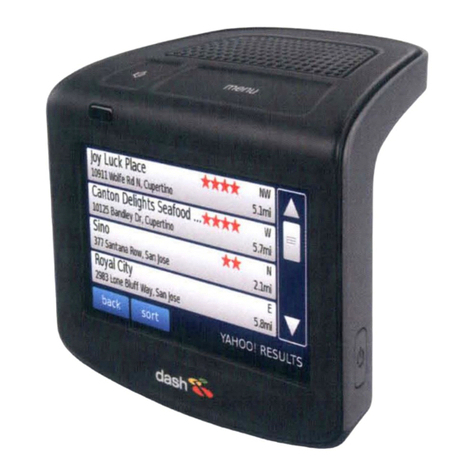
FIGURE 1. Viper Pro Console
The Viper Pro console provides on-screen guidance in the form of a Course Direction Indicator (CDI) and on-
screen lightbar. The navigation feature has several different swathing patterns, including Straight A-B, Fixed
Contour, Last Pass, and Pivot. The Viper Pro can also control an external Raven lightbar. Refer to Chapter 9,
Viper Pro Guidance, for more detailed operation information.

Chapter 1
2 Viper Pro™ ParaDyme™ Operation Manual
Viper Pro Features
The following sections offer a brief introduction to the capabilities of the AutoFarm Viper Pro system and some
of the optional features available for use with the precision application management system.
Speed Compensated Product Control and Datalogging
The Viper Pro is capable of controlling up to five products through product control nodes connected to a
CANbus system. Viper Pro automatically adjusts the application rate of each product according to the speed of
the vehicle, width and status of programmed sections, and a programmed target rate.
The Viper Pro is also capable of monitoring and mapping applications controlled by another Raven serial
console, such as the Raven SCS 440 or 460 consoles, via a serial connection. Variable Rate capabilities of the
Viper Pro may also be used with a Raven serial console.
A real-time, as-applied map is displayed on-screen while application and scouting information is logged and
saved by the Viper Pro. This “Job” information can then be transferred to a USB flash drive, copied to a home
or office PC, and used to create printed reports and coverage maps.
Variable Rate Application (VRA)
Viper Pro can provide automatic variable-rate control for liquid, granular, spinner control, anhydrous, or
injection products. Viper Pro will also datalog and store as-applied data or scouting information. This as-
applied information can be used to compare the field prescription to the actual application and provide valuable
documentation of the application. The Viper Pro console will store the application report and datalogged
information as a very efficient “Rbin” file. See Chapter 10, File Maintenance, or Appendix B, Understanding
Viper Pro Files, for detailed information. Raven provides, at no additional charge, an easy to use Rbin Viewer
tool that allows the operator to view and print Viper Pro application reports or export the logged data as a
shapefile. The common shapefile format can be used with many application management software packages.
Single Product VRA (Variable Rate Application) comes standard with your Viper Pro console. With the Multi-
Product VRA upgrade (P/N 077-0171-152), the Viper Pro console can variable rate up to five products
simultaneously.
On-Screen Guidance
The Viper Pro console provides on-screen guidance in the form of a Course Direction Indicator (CDI) as well as
an on-screen lightbar. The Guidance feature offers Straight A-B, Last Pass, Fixed Contour, and Pivot swath
patterns to match your field and application. In addition, GPS information may be sent to an external Raven
lightbar. See Chapter 9, Viper Pro Guidance, for more detailed operation.

Manual No. 016-0171-365 3
Introduction
1
Optional Features
In addition to the product application control capabilities of the console, several optional Raven components
and systems are available for use with the Viper Pro.
•AccuBoom™ automatic boom section control systems.
•AccuRow™ automatic planter section control systems.
•Glide Series AutoBoom™ automatic boom height management systems.
•WatchDog Sprayer Station for automated weather information collection and reporting.
•SCS Sidekick™ direct injection systems for automatic rate control of injected chemicals.
Note: Please see Chapter7, Using AccuBoom™, or Chapter 8, Using AutoBoom™, for more information
on using these features with the Viper Pro console.
The Viper Pro is also capable of integrating into many Raven CANbus control systems or with Raven standard
serial interface control consoles.
Contact your local dealer for more information about these and other optional features and components
available for use with the AutoFarm Viper Pro system.
Roof Module
The Novariant Roof Module is a GPS receiver with a multi-antenna array mounting on the roof of your vehicle.
The roof module is factory calibrated for rapid installation and setup. The roof module also contains a radio for
receiving corrections from a base station.
The roof module utilizes a quick-release mechanism for easy transferring between vehicles and is outdoor
rated to IP67 standards.
FIGURE 2. Paradyme™ Roof Array

Chapter 1
4 Viper Pro™ ParaDyme™ Operation Manual
The Viper Pro User Interface
The following sections offer an overview of the user interface features of the Viper Pro console.
Active Matrix Transflective Touch Screen
The Active Matrix Transflective touch screen allows screen visibility through a wide range of lighting conditions
and even in direct sunlight while the touch screen functionality places menus, options, and features literally at
the operator’s finger tips. Additional setup and information screens are accessible through the Menu.
CAUTION
To avoid damaging the touch screen, do not
use sharp objects, such as ball point pens,
pocket knives, screwdrivers, etc. on the Viper
Pro display.

Manual No. 016-0171-365 5
Introduction
1
Front Panel
The front panel of the Viper Pro provides easy access to the power button and the USB connection. The
following is a description of the front panel features of the Viper Pro:
FIGURE 3. Viper Pro Front Panel
Press the Power button to start up the Viper Pro console. The console takes approximately 30 seconds to
power up.
A USB Port is conveniently located on the front of the Viper Pro console. Insert a USB flash drive into this port
to transfer compatible Viper Pro files.
Note: The USB flash drive must be formatted with the Viper Pro file structure. See Chapter 10, File
Maintenance, for setting up the required file structure on your USB flash drive.
File Transfer
The Viper Pro features internal memory to store files for current job and field information. The internal memory
should not be used for long term storage and files should be periodically transferred to a home or office PC for
archiving and printing job reports. When transferring files, use a USB flash drive, or “thumb drive,” with at least
256 MB of memory. USB flash drives may be purchased directly from Raven Industries (1 GB USB Flash Drive
P/N 524-0002-065) as well as many retail locations.
FIGURE 4. USB Flash Drive
Note: Install the USB flash drive only when you want to transfer files. Do not start the Viper Pro or leave
the USB “thumb drive” in the Viper Pro during normal operations.
NOTICE
Failure to close a job before turning the
console’s power off may result in a loss of
information for that job. Make sure to properly
close any open jobs before shutting down the
console.
Power Button
USB Port
Touch Screen

Chapter 1
6 Viper Pro™ ParaDyme™ Operation Manual
Rear Panel
The following is a brief introduction to the ports and connectors available on the back of the Viper Pro console.
The rear panel offers additional USB Ports as well as an ethernet port for connecting to the AutoFarm
Paradyme™ Roof Array.
FIGURE 5. Viper Pro Rear Panel
The connectors for the main and auxiliary interface cables are also located on the back of the Viper Pro.
The console’s part and serial numbers, and revision letter, are printed on the tag located on the back of the
console. Please have this information available should you need to contact customer support.
Built-In Mounting Bracket
USB Ports Ethernet Port
Main Interface
Cable Connector
Auxiliary Interface
Cable Connector

Manual No. 016-0171-365 7
Introduction
1
Required System Setup
AutoSteer Setup Steps
The steps listed below give an overview of procedures that must be successfully completed in order to ensure
proper ParaDyme system operation. Refer to the AutoFarm Paradyme User Manual (P/N 602-0242-01-A), to
begin setting up the Paradyme AutoSteer system.
1. Create a vehicle, giving name, selecting type, and entering required dimensions, if the defaults are not OK.
2. Configure the radio channel to match your base station.
3. Configure the WAAS/EGNOS PRN to match your geographical position.
4. The vehicle is now ready to AutoSteer.
Note: Tuning may be required, depending on vehicle type.
Product Control Setup Steps
Setup the Viper Pro control system for your specific application and vehicle. Refer to Chapter 3, CAN
(Controller Area Network) Setup, to verify the following settings prior to starting an actual application:
1. Default units, speed sensor type and speed cal
2. Application and valve type
3. Implement or boom section cal
4. Verify appropriate product control cals (i.e. valve cal, meter cal, and/or spreader constant) for your
application. See Chapter 3, CAN (Controller Area Network) Setup, for more information.
Note: Tuning may be required, depending on vehicle type.

Chapter 1
8 Viper Pro™ ParaDyme™ Operation Manual
Viper Pro Care and Use
Refer to the following guidelines for proper care and use of the Viper Pro console.
•Do not apply any type of liquid or glass cleaner directly to the surface of the touch screen. Harsh chemicals
may damage the touch screen. Clean the touch screen and console exterior as needed with a soft cloth
dampened with glass cleaner. Apply the cleaner to the cloth and then wipe the screen gently.
•Do not use any type of pointed or sharp instrument on the Viper Pro touch screen. Only your fingertip or
approved stylus should be used when interfacing with the console.
•Do not expose the Viper Pro console to precipitation or other forms of liquid.
•Mount the console securely and route cables to prevent pinching or a tripping hazard.
•When temperatures are expected to be below 10° Fahrenheit [-12° Celsius], the Viper Pro console should
be removed from the vehicle and stored in a temperature controlled environment.
CAUTION

CHAPTER
2
Manual No. 016-0171-365 9
C hapt er 2
Installation, Start Up
& Registration
Overview of the Installation Process
The following sections are intended as an overview of the Viper Pro installation process. These instructions
cover basic installation of the Viper Pro console and supplied components and cabling.
Note: For instructions on installing additional hardware with your Viper Pro, refer to instructions provided
with the additional or optional component(s). Instructions for building a CAN (Controller Area
Network) System can be found in Chapter 3, CAN (Controller Area Network) Setup. For additional
system diagrams, see Appendix A, System Diagrams.
Basic installation of the Viper Pro system is as follows:
1. Review Kit contents
2. Mounting the Viper Pro console
3. Route and connect Main Interface Cable
4. Connect any optional CAN components
Kit Contents
Before proceeding with the installation of your AutoFarm Viper Pro system, review the following components of
your Viper Pro kit;
TABLE 1. AutoFarm Viper Pro Kit (P/N 117-0171-292)
Part/Description Raven Part Number
Console, AutoFarm Viper Pro 063-0171-151
Cable, Main Power 115-0171-781
Manual, AutoFarm Viper Pro Operation 016-0171-365
Manual, AutoFarm ParaDyme User 016-0171-366
Quick Reference Guide, AutoFarm Viper Pro 016-0171-367
Arm, RAM Mounting 103-0159-013

Chapter 2
10 Viper Pro™ ParaDyme™ Operation Manual
Note: If the Viper Pro will be providing product control through a CANbus system, a boom sense/speed
node (P/N 063-0172-272) and at least one single product node (P/N 063-0172-373) must be
connected to the CANbus.
Mounting and Installation
The following procedure will guide you through mounting the Viper Pro console and connecting the required
cables.
Roof Module
The roof module utilizes a quick-release mechanism for easy transferring between vehicles. Refer to the
AutoFarm ParaDyme User Manual for installation instructions.
The Main Power Cable is connected to the vehicle power outlet located in the vehicle’s cab.
Screw, 1/2” Mounting 311-0002-042
Screw, 3/4” Mounting 311-0007-037
Nut, Lock 312-4000-162
Plate, Mounting 107-0171-824
Other Available Components Raven Part Number
Cable, Auxiliary Interface 115-0171-745
Cable, Combo Interface 115-0171-744
Cable, Adapter, Viper to Viper Pro 115-0171-742
CAN Node, Boom/Speed 063-0172-272
CAN Node, Single Product 063-0172-373
Part/Description Raven Part Number
Table of contents
Other AutoFarm GPS manuals
