Automata EVA Use and care manual

The goal of this manual is to provide helpful information on the particulars of
Eva’s
software, electronics and mechanics.
It does not contain comprehensive safety or risk information.
Before reading this manual, attempting to set up or operate the robot,
ensure you read and understand the separate safety manual and carry out a
risk assessment.
Download the latest version of this manual from https://automata.tech
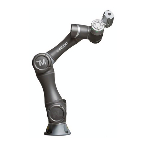
Eva Robotic Arm
Technical Reference User Manual
Version 1.0 - November 2018

Contents
Installing the Robot
Physical Setup
Tooling
Powering on and Connecting
Updating the Robot
Controlling the Robot
Ways of Interfacing
Waypoints
The Timeline
Executing & Monitoring Toolpaths
Programming with Choreograph
Programming with the API
Electronic Interfaces
Base Interface
1. Emergency Stop Connection
2. Reserved Stop Connection
3. Base I/O
4. Power Input
5. USB x 2
6. Ethernet
Head Interface
Mechanical Overview
Dimensions & Axes
Ratings & Limitations
Getting the Most Out Of Eva
3
8
18
26
29
2

Installing the robot Physical Setup
In summary, screw the robot base into a supportive surface with four M6 screws
or bolts. Connect the emergency stop (consult the safety manual) and plug the
robot into mains power.
For greater precision and consistency between installations, use two dowel pins,
5 mm in diameter, to align the two reference holes on the baseplate (located
inwards from the mounting holes, as shown on the diagram) with similar slots in
your work surface. The pins should rise a maximum of 5 mm above the surface
of the baseplate.
In the box you will find Eva, an emergency stop switch and a power supply
(with cables for each), a safety manual, and a user manual.
Consult the safety manual for information on proper installation.
01
3

Tooling
Eva has an aluminium flange, or toolplate for attaching tools such as grippers or
sensors.
It has an ISO 9409-1 designation of 40-4-M6. This means it uses 4x M6
threaded holes arranged in a circular pattern, 40 mm in diameter. Refer to the
drawing for detailed dimensions.
A locating hole, 6 mm in diameter, is present between two of the mounting holes.
Many tools include a locating pin that slots tightly into this hole to home the
orientation of the tool and reduce unwanted rotation. This pin should be aligned
before screwing in the tool.
The inner holes of the toolplate fix it to the robot. They sit within a recessed circle
that also helps to align some tools.
Powering on and Connecting
Power
Power will only be available to Eva’s joints while the emergency stop button
(e-stop) is connected and released. The e-stop is activated by a simple push, and
released by twisting the button in the direction shown on the top.
The main power button is located on the robot base, above the input/output
panel. This button does not disconnect physical power from the robot.
4

The robot will be in a sleep state when first connected to a power source. Wake
the robot by pushing the button once. When the system is awake and running,
the button indicator ring and the LEDs on the robot head will illuminate white.
When the robot is idle, press the power button once to shut the robot down. A
shutdown can be forced by pressing and holding the power button for several
seconds. This is not an emergency procedure. Refer to the safety manual for
information on e-stops and other protective features.
Communication
Connect to the robot for the first time via wifi or ethernet.
Wi-Fi
Eva will be available as its own wireless access point, identified with the format
eva-Name. Connect to this access point with the password on the sticker below,
open a browser and navigate to the URL eva.automata or 172.16.172.1.
Ethernet
To connect via ethernet, configure your host side interface to IP: 172.16.16.1,
Subnet Mask: 255.255.255.0. Open a browser and navigate to 172.16.16.2.
Once connected, it’s possible to configure the robot to connect to another wifi
access point or an ethernet network with a static IP. If Eva detects it has lost its
connection, or has been configured with invalid settings, it will continue to at-
tempt to connect for three minutes, before rolling back to the default access
point and ethernet configuration.
First time setup
After navigating to Eva’s IP address for the first time, a setup screen will be
displayed:
5

Use this screen to provide credentials for the robot administrator. This user has
the ability to add and remove other users from the robot.
The second part of first time setup allows a connection type to be specified.
Access Point Mode causes the robot to behave like its own wireless network,
with the SSID displayed below. This screen also provides an opportunity to
modify the Passphrase for connecting to this access point. IP settings will be
determined automatically via DHCP.
Wi-Fi Mode causes the robot to behave like a device connected to a local wire-
less network. The user must provide the SSID and Passphrase for the chosen
network. Eva must also be assigned a unique Static IP, and a valid Netmask and
Gateway in order to connect. On a home network, a typical Netmask and
Gateway might be 255.255.255.0 and 192.168.1.1 respectively.
Consult your network admin for advice on the appropriate configuration.
Ethernet Mode is similar to Access Point mode, but the user can specify the IP
settings for the robot when it’s connected to a device or network via ethernet.
Ethernet Mode will ‘remember’ the passphrase set for the wireless access point
in Access Point Mode. Ethernet connections are also possible in Access Point
Mode and Wi-Fi Mode, but IP settings for the robot will return to default.
6

Updating the Robot
Download the latest Eva software and firmware packages from https://automata.tech.
To update the robot, navigate to the config page of Choreograph and take
ownership.
Drag and drop the relevant robot update package (or select ‘upload and install’)
to the Software Update section of the page. Confirm the update by clicking
‘Yes’. You will be disconnected.
Do not attempt to operate the robot or use Choreograph until the update is
complete. Never unplug the robot while updating.
7

Controlling the Robot Ways of interfacing
02
As long as Eva remains online and errorless, it will execute any valid instruction
from the device (such as a computer or tablet) with Robot Ownership.
The simplest way to take ownership and send instructions to the robot is with
Choreograph - a simple user interface accessible with your web browser.
Engaging the lock button on the main Choreograph toolbar claims ownership
and prevents any other device from doing the same, until the lock is disengaged
or the user is idle for five minutes.
Choreograph provides a Dashboard and a Viewer for manipulating a 3D virtual
robot, which the physical robot can imitate.
Many programs require no code at all from the user. Choreograph can instruct
the robot to execute a single Toolpath indefinitely, or for a fixed number of
cycles. Toolpaths consist of a series of Waypoints along a Timeline, each
specifying a position and orientation for the robot’s toolplate.
Advanced programs might involve multiple toolpaths, triggered by certain
conditions, and some applications might circumvent toolpaths entirely, relying
instead on rotating individual joints by a specific number of degrees.
Either can be achieved by writing code that sends API requests to the robot. In
these cases, Choreograph still serves as a handy tool for monitoring the robot
and managing user permissions.
8

Waypoints
There are three ways to create waypoints:
1. Teach by example
2. Manipulate existing waypoints
Press and hold the backdriving button on the head to release the brakes and
physically manipulate the robot into a desired position.
Release this button and press the waypoint button to create a waypoint. This
will be picked up by the device with robot ownership (see: Installing the
robot - Powering On and Connecting).
Click on a waypoint in the 3D Workspace of the Choreograph Viewer to select
it. If multiple waypoints, or the yellow gizmo sphere, are nearby, a wheel menu
will open. Use this menu to specify which waypoint you intend to select:
For instance, if a user has taken robot ownership with Choreograph, the new waypoint will appear
in the 3D workspace of the viewer, at the current robot position. The waypoint will become visible
when the robot moves to a new location.
9

These icons:
3. Off-the-robot Programming
a.
b.
c.
d.
e.
f.
Make a copy of the waypoint
Add a text label to the waypoint
Delete the waypoint
Move the waypoint to a new absolute position specified by XYZ
coordinates, relative to the base of the robot
Move the robot (real or virtual, depending on ownership) to this waypoint
Close the menu
At the bottom of the menu, the waypoint icon can be clicked and dragged into
the timeline (see Populating the Timeline).
Besides setting absolute position (d. In the wheel menu), waypoints can also
be moved with gizmo controls. These are represented as red, green and blue
gimbals which can be rotated, and axes which can be shifted. This is achieved in
both cases by clicking and dragging.
Alternatively, double click an axis or gimbal to specify movement by a certain
number of millimetres or degrees.
Even if Choreograph is ‘unlocked’ and does not have robot ownership, it
remains connected to the robot. In this mode, it’s possible to work on toolpaths
without being affected by the movement of the real robot.
When a waypoint is selected, a new wheel menu will open:
10

a.
b.
c.
a.
b.
c.
d.
e.
Selecting the yellow positioning sphere at the end of the toolplate provides
access to the same gizmo controls that are used to move waypoints
Selecting any part of the robot and clicking the Absolute Position icon
opens the same coordinate input controls that are used to move waypoints
Selecting any joint of the robot allows the user to rotate that joint
individually by clicking and dragging
Name the current toolpath
Save the toolpath
Save the toolpath as a new file
Share the toolpath with another user
Close the current toolpath and return to the toolpath selection screen
Regardless of whether Choreograph has robot ownership, selecting any part of
the robot in the 3D Workspace allows the user to create a waypoint at the virtual
robot’s current position.
If Choreograph does not have robot ownership, the virtual robot can be manip-
ulated independently:
The Timeline
Click on the tab in the bottom left corner of the Choreograph Viewer to reveal
the Timeline at the bottom of the screen. The timeline reflects the actual actions
Eva will take when the current toolpath is uploaded and executed. Any waypoints
in the 3D viewer that are not present on the timeline will not affect the real robot,
although they will be saved along with the timeline in the toolpath file.
To add a waypoint to the timeline, select a waypoint in the 3D workspace, and
click and drag its icon onto the timeline. Waypoints can be rearranged by
dragging them into desired positions along the timeline.
The top left controls above the timeline deal with the file system:
11

The remainder of this toolbar deals with the properties of the toolpath:
Beneath the timeline slider is a toolbar that deals with special waypoints and
views:
a.
b.
c.
d.
e.
a.
b.
c.
d.
e.
f.
g.
h.
i.
Reassign numbers to waypoints based on the order in which they were
created
Reassign numbers to waypoints based on the order they first appear on
the timeline
Open the toolpath settings menu, dealing with global speed and analog
I/O modes
The total duration of the timeline is displayed, based on current settings
Simulate the toolpath; restart, play, skip or loop the timeline
(Off-the-robot only) Beneath this toolbar is a timeline slider that can be
dragged to simulate the toolpath.
Zoom out from the timeline
Restore the timeline to its default view
Zoom in to the timeline
(note: navigate by clicking and dragging in empty space on the timeline)
Drag into the timeline to create a grid loop sequence
Drag into a grid branch to create a grid waypoint
Drag into the timeline to create a conditional branch
Drag into the timeline to create an I/O action
Drag into the timeline to create a wait action
Drag into a conditional loop branch to create a restart action
(note: see Programming with Choreograph for information on grids and
conditions)
12

Right click on any waypoint in the timeline to change its properties:
There are three types of trajectories between waypoints:
The speed of a single trajectory can be defined in one of two ways:
a.
b.
c.
a.
b.
Joint Space trajectories - represented by circles on the timeline - instruct
the robot to move to the waypoint in a way that is ‘natural’ for the joints
Linear trajectories - represented by squares on the timeline - instruct the
robot to move its end-effector to the waypoint in a straight line. This re-
sults in cartesian motion
Pass Through trajectories - represented by triangles on the
timeline - instruct the robot to pass through a waypoint without stopping.
This results in cartesian motion
By defining a duration for the trajectory, in seconds.
By assigning a scale factor in relation to maximum robot speed.
(note: individual trajectory speeds override global speed. Setting a scale
factor greater than 0.33 may result in speeds greater than 250 mm per
second. This kind of motion is not considered safe for desktop operations.
Consult the Safety Manual for more information.)
Special waypoints have their own set of properties to define, some of which do
not relate to movement trajectories.
13

Executing and Monitoring Toolpaths
When Choreograph has robot ownership, it can send instructions to the robot.
Note that the active toolpath in the robot memory is not necessarily the same
as the toolpath shown in Choreograph. New toolpaths must be uploaded to the
robot memory before they can be executed.
The robot owner has access to a small control panel on the left hand side of the
viewer. These controls:
The same controls are available in the
dashboard, along with information
about the robot’s status and a toolpath
selection menu:
By default, Choreograph will instruct the robot to repeat the toolpath
continuously. Toggle the Loop Iterations slider to specify a certain number of
cycles to run the toolpath. Looping is only possible for toolpaths that start and
end on the same waypoint.
When the robot is running, a pause button and an end button become available
on both control panels. It is not recommended to use the pause button at high
speeds (greater than 0.33), as this will result in a hard stop and repeated use may
result in damage to the brakes. The end button will allow the robot to finish its
current loop before coming to a stop.
a.
b.
c.
Upload the toolpath shown in the viewer to the robot memory
This will overwrite any toolpath currently remembered by the
robot
Instruct the robot to return to the starting point of the toolpath in
its memory
Execute the toolpath in robot memory
14

Programming with Choreograph
Dragging the output icon onto the timeline opens a
dialog box, asking for a specific electronic output pin and a
value. When the toolpath is executed and this waypoint is
reached, your chosen signal will be sent to this pin.
Some tools require signals from more than one pin to take
action. For instance, a gripper might open when it receives
a 0 at [input a] and a 1 at [input b]; and close when it
receives a 1 at [input a] and a 0 at [input b].
Dragging the grid icon onto the timeline opens a dialog
box, asking for the number of rows and columns in your
grid. This creates a new grid loop:
Drag a grid waypoint from the special waypoints toolbar
onto the higher branch of the grid loop to specify the point
in time when the robot should move to a grid position.
When the toolpath is executed, the loop will be repeated
the same number of times as grid positions (eg: a 3x3 grid
will iterate 9 times). In each iteration, the grid waypoint
specifies a new position, completing each row before
moving to the next.
Right click on a grid waypoint to modify its properties, including specifying a
z offset. This function sets the waypoint to a position a certain number of milli-
metres above the grid position (or below if using a negative value).
Drag additional waypoints to the grid loop to complete the toolpath.
There are always three slots in the grid properties function. Fill these slots with
waypoints to specify the first position of the grid, the final position on the first row, and
the first position on the final row. A plane will appear in the 3D workspace to visually
represent the new grid.
Communicating with other devices
15

Conditional Branches
Dragging the conditional branch icon onto the timeline creates a new branch,
starting with a conditional waypoint.
If the condition is true, any waypoints along this branch will be executed. If the
condition is false, the branch will be skipped (ie: the central, empty branch will
be chosen).
It’s also possible to add or remove additional branches to the same tree, using
the plus and delete icons respectively. If several conditions are true, the branch
that was created first will be executed, and the other branches will be skipped.
Eg: If there are four branches, they will be evaluated in the order shown to the
right, and only the first branch to return ‘yes’ to the condition will be executed.
Restart waypoints can also be added to conditional branches, instructing the
robot to execute the toolpath again from the beginning.
16

Programming with the API
After setting up Eva for the first time with Choreograph and creating a user pro-
file, it’s possible to generate an API token from the user profile menu.
A quality control application could be programmed as follows:
Picking up a component and showing it to a measuring device.
Moving the component to the ‘good’ drawer
Moving the component to the ‘bad’ drawer
Calls the API to execute toolpath 1
Waits for information from the measuring device
Calls the API call to execute toolpath 2 or 3 depending on the
result
Repeats
Visit https://automata.tech for up-to-date API documentation
A) Use Choreograph to create and save three toolpaths:
B) Write code that:
C) Run the program
i)
ii)
iii)
i)
ii)
iii)
iv)
17

Electronic Interfaces Base Interface Overview
03
The main robot computer is stored in the base. Physical controls are available
on the rear.
Power Button
The robot power button is found above the Input/Output panel.
Input/Output Panel
Key:
1. Emergency Stop Connection
Emergency Stop Connection
Unused (reserved for future expansion)
Base I/O
Power Input
USB x 2
Ethernet
Please consult the safety manual for information about the appropriate instal-
lation of Eva’s emergency stop function.
This port is designed for a DPDT, 2NC e-stop push button switch conforming to
IEC 60947-5-5, such as the button provided with Eva, or the ABB CEPY1-1001.
The interface is a standard A-coded circular M8 female connector (IEC 61076-
2-104). The pinout can be seen below
1.
2.
3.
4.
5.
6.
18

M8 Connector Pin Colour PIN Function
1 Brown Eb_24V
2 White Eb -E- Stop Channel A
3 Blue Ea -E-Stop Channel B
4 Black Ea _24V
This port is not in use, and is reserved for future expansion.
Download the latest software, along with the latest version of this manual from
https://automata.tech.
The connector pins are spring terminated. Press and hold the orange tab to
retract the spring and insert a stripped wire end, then release the orange tab to
engage the spring and lock the wire in place. The connector is designed for use
with 16 - 24 AWG wire.
A) Power
There are four 24 V power pins on the base I/O, which can collectively source
a maximum of 1.875 A. These are found in the first four columns of the top row:
2. Reserved Stop Connection
3. Base I/O
24 V (Pin 1)
Base Di1 (Pin 2)
24 V (Pin 3)
Base Di1 (Pin 4)
24 V (Pin 5)
Base Di1 (Pin 6)
24 V (Pin 7)
Base Di1 (Pin 8)
19

Base Do1 (Pin9) Base Do2 (Pin 11) Base Do3 (Pin 13) Base Do4 (Pin 15)
GND (Pin 10) GND (Pin 12) GND (Pin 14) GND (Pin 16)
Signal Min Typ Max
VIABS Absolute max input voltage -60V - 60V
VITypical input voltage range -3V - 30V
VIL Low level threshold voltage for input transitioning from high
to low
8.53V 9.26V 10.5V
VIH High level threshold voltage for input transitioning from low
to high
9.88V 10.46V 11.10V
II Current (high input) 2.05mA - 2.56mA
B) Digital Inputs
C) Digital Outputs
Beneath the power pins are four digital input
pins. These are 24 V IEC 61131-2 Type-3 current
sinking inputs, for use with PNP type sensors or
outputs.
The robot and the outputting device should
share a common ground, to ensure all signals are
referenced to the same level.
There are four 24 V IEC61131-2 sourcing output pins on the base I/O,
accompanied by four ground pins:
20
Other manuals for EVA
1
Table of contents
Other Automata Robotics manuals
