Automated Processes, Inc. 529 User manual
\
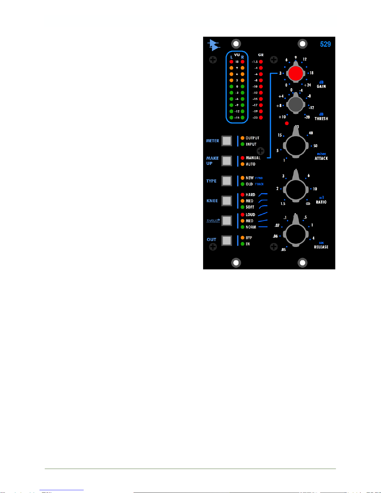
529 Stereo Compressor
OPERATOR’S MANUAL
V1.5
Written for Automated Processe s I nc or p orated
by Daniel Pfeifer 20 18

8301 Patuxent Range Road
Jessup, MD 20794 USA
301-776-7879
http://www.apiaudio.com

Table of Contents
Introduction ..................................................................................... 2
Features .................................................................................................2
Overview .......................................................................................... 3
Compressor Controls ........................................................................ 3
THRESHold .............................................................................................3
RATIO.....................................................................................................4
ATTACK...................................................................................................4
RELEASE .................................................................................................4
MAKE UP GAIN .......................................................................................4
Compressor TYPE ............................................................................. 5
NEW (Feed-Forward)..............................................................................5
OLD (Feed-back) ....................................................................................5
Compression KNEE ........................................................................... 6
HARD KNEE Compression .......................................................................6
MEDIUM KNEE Compression ...................................................................7
SOFT KNEE Compression ........................................................................7
THRUST®........................................................................................... 8
THRUST® NORMal....................................................................................8
THRUST® MEDium ...................................................................................9
THRUST® LOUD .......................................................................................9
Compressor Bypass (OUT).............................................................. 10
Meters ............................................................................................ 10
Stereo VU Meter ...................................................................................10
GR (Gain Reduction) Meter................................................................... 11
529 S t e r e o C o m p r e s s o r A P I
2
Introduction
The new 529 Stereo Compressor combines the
unmistakable sound of API’s compression technology
with the convenience and popularity of the API 500
Series format.
Carefully designed to deliver a wide range of
compression options, the 529 delivers warmth, clarity
and punch, whether used for subtle adjustments or
heavy compression effects.
Based on the unprecedented success of the 2500, the
529 takes many of the features and controls from
API's famous stereo bus compressor and puts them
into the first dual slot 500 series module from API.
Using API's discrete op-amps and transformer
technology, the 529 delivers the legendary analog
sound of API.
The 529 is a two-channel, stereo-linked dynamic
processor designed for stereo program bus
compression and compression of any stereo audio
source. The audio input signals from both channels
are combined in a true-RMS power summing fashion
to create the compression control signal for the
detection path. Then, the resulting compression
signal is applied evenly to both channels for proper
balance. All front panel settings control both channels
simultaneously.
This stereo compressor features API's patented
THRUST®circuitry for a punchy low end, along with
an OLD/NEW switch that lets you choose between
classic and modern compression characteristics: OLD
for vintage-style feedback compression and NEW for
today's more common feed-forward compression. The
3-position KNEE switch adjusts the shape of the curve at the onset of compression for an "over-easy"
type compression resulting in a very natural, uncompressed sound or a typical sharp knee type that
lends itself to a much more severe limiting effect.
The Auto MAKE UP gain function lets you adjust ratio and threshold controls without affecting the
output level. Alternately MAKE UP gain can be set manually.
Features
Continuously variable 31-position detented controls for Gain, Threshold, Ratio, Attack & Release
Stereo 10-segment LED VU meters show selectable Input or Output levels
10-segment LED Gain Reduction meter
“Over Threshold”LED illuminates when input audio cross the set THRESHold
Patented THRUST®filter for frequency dependent side chain control
3 selectable compressor curve KNEE settings
Selectable NEW or OLD switch for feed-forward or feed-back operation
Selectable automatic or manually variable compressor make-up gain
Full hard-wired relay bypass
Audio circuit uses 2510 and 2520 discrete op amps with transformer output
2-space 500 Series installation
529 S t e r e o C o m p r e s s o r A P I
3
Overview
The 529 Compressor provides a comprehensive suite of controls:
THRESHold: The level at which compression begins (+10dB to -20dB)
Threshold LED: Indicates when the input audio crosses the selected THRESHold level
RATIO: The amount of compression applied after threshold (1.5:1 to ∞:1)
ATTACK: The time it takes for the compressor to respond (1 to 50 m/sec)
RELEASE: The time it takes the compressor to return to unity gain (.05 to 4 seconds)
METER: Selects OUTPUT or INPUT as the source for the stereo VU meter
VU (Stereo VU Meter): Stereo 10-segment LED VU meter (selectable OUTPUT or INPUT)
GR (Gain Reduction) Meter: 10-segment LED gain reduction meter
MAKE UP: Selects AUTOmatic or MANUAL MAKE UP gain
GAIN: Manual MAKE Up gain control (0dB to +24dB of output gain when MANUAL is engaged)
TYPE: NEW (feed-forward) or OLD (feedback) detection path topology
KNEE: The characteristic of the response curve at the onset of compression.
THRUST®: Patented circuit that inserts a filter before the RMS detector
OUT: Toggles to swich gain reduction in or out or engages hard bypass
Compressor Controls
THRESHold
THRESHold: Sets the level at which compression begins
Continuously variable range between +10dB and -20dB
Detented rotary pot for easy recall
Threshold LED: Illuminates when the input audio crosses the level set
by the THRESH control
Illuminates in red when active
529 S t e r e o C o m p r e s s o r A P I
4
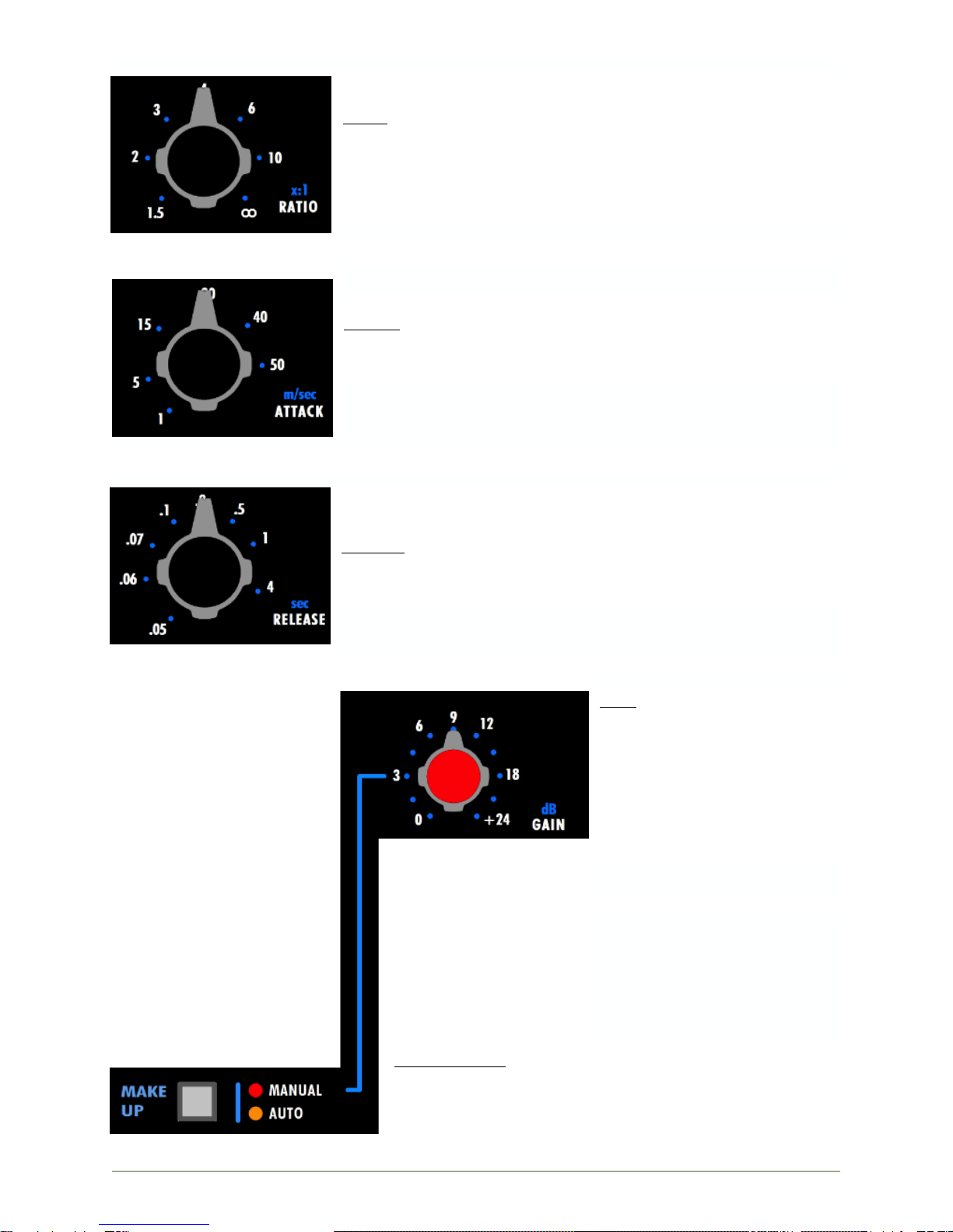
RATIO
RATIO: Sets the ratio of input vs. output levels for signals that fall
above the set THRESHold
Continuously variable between 1.5:1 and ∞:1 (x:1)
Detented rotary pot for easy recall
Compression with RATIOs of 10:1 or greater is generally
considered to be limiting
ATTACK
ATTACK: Sets the time it takes the compressor to react when the
level exceeds the set THRESHold
Continuously variable between 1 and 50 milliseconds (m/sec)
Detented rotary pot for easy recall
RELEASE
RELEASE: Sets the time it takes the compressor to recover to unity
gain after the level falls below the set THRESHold
Continuously variable between .05 and 4 seconds (sec)
Detented rotary pot for easy recall
MAKE UP GAIN
GAIN: Manual make up gain
(output level)
Continuously variable
between 0dB and +24dB
Active only when the
MAKE UP function is set
to MANUAL
Detented rotary pot for
easy recall
The 529 Compressor provides
automatic and manual make
up gain functions.
AUTOmatic make up gain
allows the RATIO & THRESH
controls to be adjusted
without affecting the output
level.
MANUAL make up gain
engages the GAIN control to
allow make gain to be set
manually.
Use the MAKE UP switch to
select MANUAL or AUTOmatic
make up gain functions.
MAKE UP (gain): Toggle to select the make up gain function
MANUAL: Engages the manual make up gain function
&GAIN control (red LED)
AUTO: Engages the automatic make up gain function
(yellow LED)

529 S t e r e o C o m p r e s s o r A P I
5
Compressor TYPE
The 529 Compressor can be set to operate in two circuit topologies that determine where the signal
that feeds the RMS detector comes from:
OLD: Feed-Back topology: The RMS detector receives the signal from after the VCA
NEW: Feed-Forward topology: The RMS detector receives the signal from before the VCA
NEW (Feed-Forward)
In a feed-forward compressor, the RMS detector normally gets its signal from a split of the input sig-
nal. (The detector path can alternately get its signal from a Side Chain Input.) With this method, the
RMS detector sends a signal to the VCA that is an exact ratio of the desired compression set by the
RATIO control. This is how many new VCA based compressors work. This can yield more aggressive
compression and a harder, more affected sound.
OLD (Feed-back)
In a feed-back compressor, the RMS detector gets its signal from the output of the gain reduction de-
vice (VCA). This is how older API 525, 1176 type, and 660 type compressors work. This yields a
smoother, softer, more transparent sound.

529 S t e r e o C o m p r e s s o r A P I
6
The compressor circuit topology is selected using the TYPE switch.
TYPE: Toggle to select the compressor circuit topology
NEW: Engages the feed-forward topology (yellow LED)
OLD: Engages feed-back topology (green LED)
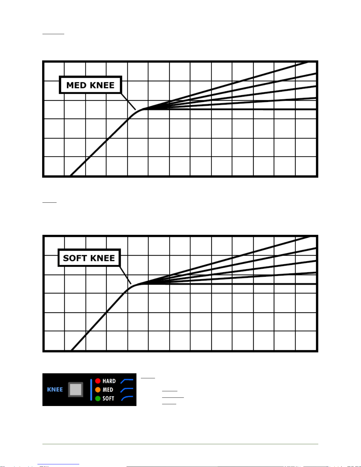
Compression KNEE
The KNEE function determines the shape of the 529 Compressor’s response curve at the onset of
compression.
The 529 Compressor has three (3) KNEE settings that control how the compressor transitions into
compression:
HARD: Sharp response curve
MEDium: Slightly rounded response curve
SOFT: Rounded response curve
HARD KNEE Compression
HARD: Sharp response curve
Immediate onset of compression (sudden transition to set ratio)
More aggressive and noticeable
Red LED
529 S t e r e o C o m p r e s s o r A P I
7
MEDIUM KNEE Compression
MEDium: Slightly rounded response curve
Moderate onset of compression (firm, but less sudden transition to set ratio)
Less aggressive and but still noticeable
Yellow LED
SOFT KNEE Compression
SOFT: Rounded response curve
Gradual onset of compression (fade-in up to the set ratio)
Similar to an “over-easy” type knee
More transparent
Green LED
The knee of the compressor is selected using the KNEE switch.
KNEE: Cycle to select the response curve at the onset of com-
pression
HARD: Sharp response curve (red LED)
MEDium: Slightly rounded response curve (yellow LED)
SOFT: Rounded response curve (green LED)
529 S t e r e o C o m p r e s s o r A P I
8
THRUST®
The 529 Compressor includes API’s patented THRUST®circuit that can be switched in or out as
needed. This places the THRUST®filter before the RMS detector that decreases the compressor’s
reaction to low frequency content. The result is a noticeable increase of punch and low frequencies,
but a uniformly compressed signal. It’s the “little more punch” switch!
The patented THRUST®circuit has been used for many years in the famed API 2500 Stereo
Compressor, ATI Paragon and Paragon II consoles, as well as the Pro6 Input Strip. This circuit places a
filter in front of the RMS detector with a slope of 10dB per decade (-3dB/8va), which is the inverse of
the pink noise energy curve. In acoustics, the pink noise curve is used to equalize energy vs.
frequency over the audio spectrum, as sound requires more low frequency energy than high frequency
energy to sound correct to your ear. In Hi-fi equipment, a “LOUDNESS” contour is used to equalize the
music at lower levels so it sounds correct. Even with this curve, there is still a substantial amount of
low frequency information compared to high frequency information in the audio signal path. When that
signal is fed into the RMS detector, the detector will process the signal into a DC control voltage based
upon those louder low frequencies, resulting in a control voltage that favors the low frequencies of the
signal, causing pumping and a loss of punch. Sometimes, this is not desirable. By engaging the
THRUST®switch, this inverse filter is placed in front of the RMS detector, evening out the energy by
lowering the energy in the low frequencies and increasing the energy in the high frequencies, so each
octave has the same energy instead of each octave having half the energy as the one lower. This
creates a unique compression effect that still reduces the overall gain, but the sound is much more
punchy and the signal actually sounds less compressed.
THRUST® NORMal
NORMal: Flat: There is no filter in the path to the RMS detector and the 529 compresses like most
units on the market today.

529 S t e r e o C o m p r e s s o r A P I
9
THRUST® MEDium
MEDium: A slight attenuation of the low frequencies and a slight boost in the high frequencies, with a
flat mid-range are applied to the signal feeding the RMS detector. This reduces the low fre-
quencies from pumping the compressor as much and increases the sensitivity of the RMS
detector to the higher frequencies, affecting the higher frequency peaks of the signal.
THRUST® LOUD
LOUD: A gradual, linear filter, down 15dBat 20Hz and up 15dB at 20kHz is applied to the signal feed-
ing the RMS detector, equalizing the energy going into the RMS detector. This decreases the
way the higher frequencies are compressed. The overall difference is a noticeable increase of
punch and low frequencies, but a uniformly compressed signal. It is the “little more punch”
function.
The THRUST®circuit can be engaged using the THRUST®switch.
THRUST®: Cycle to select the THRUST®function
LOUD: Inserts the LOUD THRUST® filter before the
RMS detector (red LED)
MEDium: Inserts the MEDium THRUST® filter before the
RMS detector (yellow LED) and LOUD (red LED)
NORMal: No filter before the RMS detector (green LED)
529 S t e r e o C o m p r e s s o r A P I
10
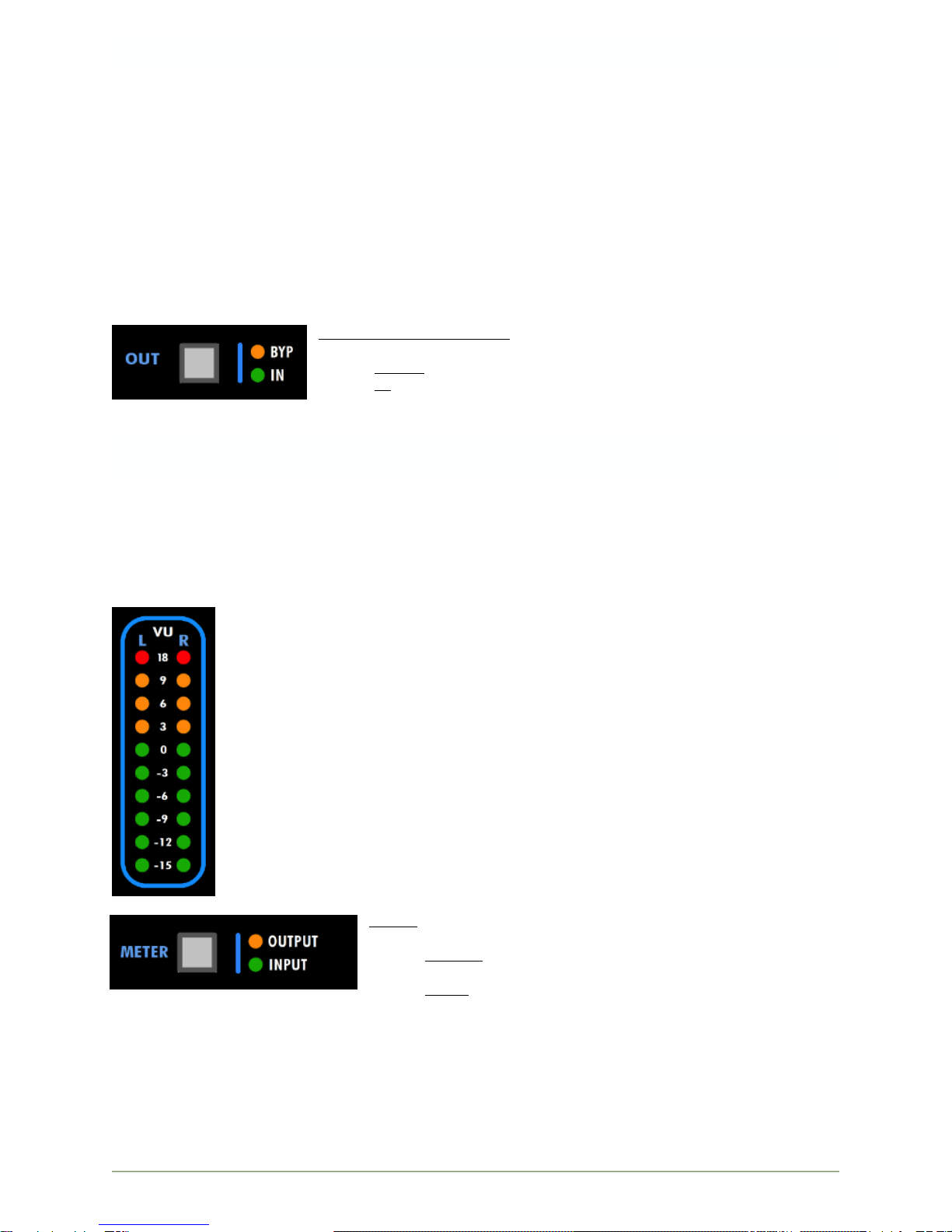
Compressor Bypass (OUT)
The 529 is equipped with a relay-based, hard-wired bypass. Press-and-hold the OUT switch to toggle
the BYPass control. When the compressor is in BYPass (yellow BYP LED illuminated), the hard-wired
bypass is engaged. In this state, the input audio signals are routed directly to the audio output
connectors and do not pass through the 529 electronics.
A momentary press of the OUT switch toggles the IN function. When the compressor is IN (green IN
LED illuminated), the compressor is active and behaves normally. When IN is disengaged (green IN
LED not illuminated), the control voltage signal is disengaged and the output signal is held at 0dB.
Audio continues to pass through the 529 electronics.
NOTE: When the 529 is powered off, it is held in the BYPass state. When the compressor is not in
the BYPass state (yellow BYP LED not illuminated), the 529 behaves normally.
OUT (Compressor Bypass): Toggle to engage and disengage the hard-
wired bypass
BYPass: Engages the relay-based hard bypass (yellow LED)
IN: Engages the compressor signal path (green LED)
Meters
The 529 Compressor is equipped with a 10-segment LED stereo VU meter and a 10-segment LED gain
reduction meter.
Stereo VU Meter
The 10-segment LED stereo VU meter can be fed from the compressor inputs or outputs.
The 10-segment LEFT and RIGHT LED VU meters have the following values:
+18dBu
+9dBu
+6dBu
+3dBu
0dBu
-3dBu
-6dBu
-7dBu
-12dBu
-15dBu
METER: Toggle to select OUTPUT or INPUT as the source for the
stereo VU meters
OUTPUT: Routes the compressor output to the stereo VU
meters (yellow LED)
INPUT: Routes the compressor input to the stereo VU
meters (green LED)

529 S t e r e o C o m p r e s s o r A P I
11
GR (Gain Reduction) Meter
A 10-segment LED gain reduction (GR) meter is provided to indicate the amount of compres-
sion being applied. When no gain reduction is being applied, none of the LED’s are lit on the
Gain Reduction meter (GR). When compression occurs, the corresponding LED’s illuminate to
indicate the amount of gain reduction. The following gain reduction increments are provided:
-1.5dB
-4dB
-6dB
-8dB
-10dB
-12dB
-15 dB
-17dB
-19dB
-23dB

8301 Patuxent Range Road
Jessup, MD 20794 USA
301-776-7879
http://www.apiaudio.com
Table of contents
Popular Air Compressor manuals by other brands


Will Burt
Will Burt 185 instructions

Gardner Denver
Gardner Denver AirSmart ELECTRA-SAVER Operating and service manual

Hyundai
Hyundai HY3150S user manual

Campbell Hausfeld
Campbell Hausfeld CE1000 Operating instructions and parts manual

Quincy
Quincy QGS 10 Instruction book

Emerson
Emerson Copeland Discus Series Application guidelines


