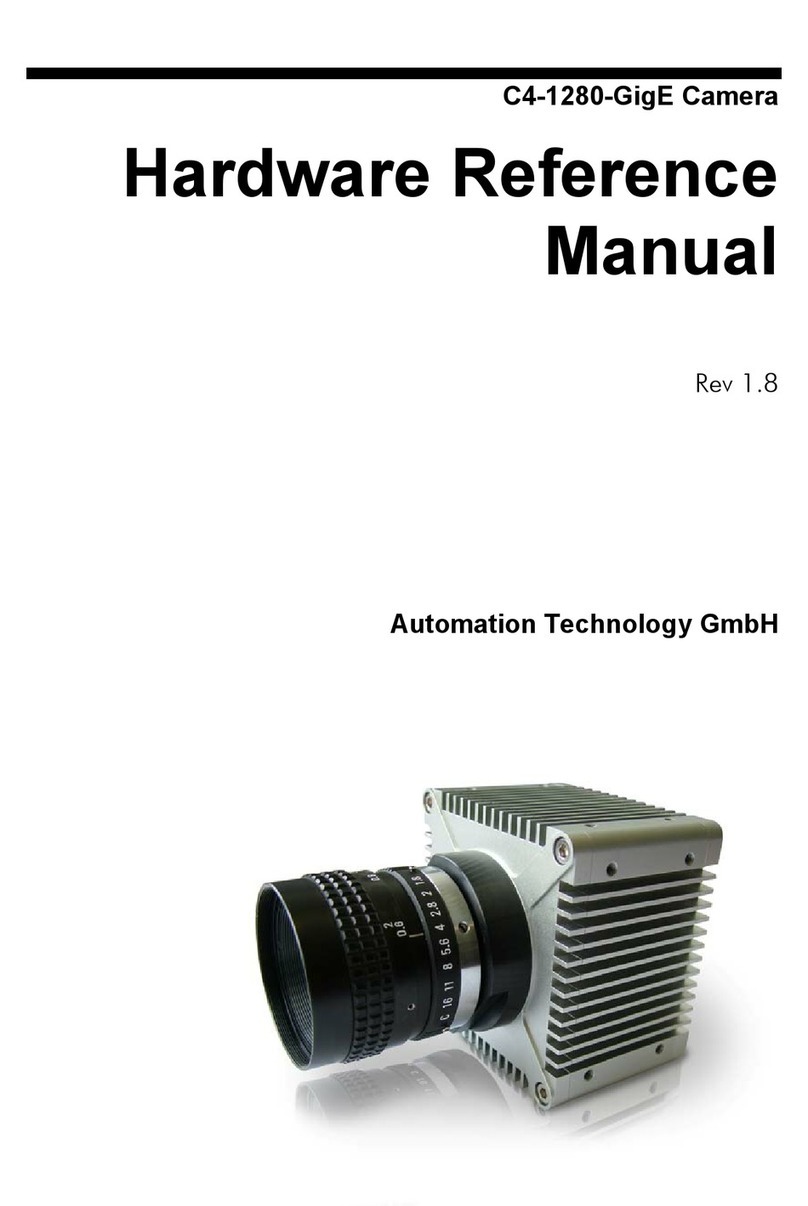
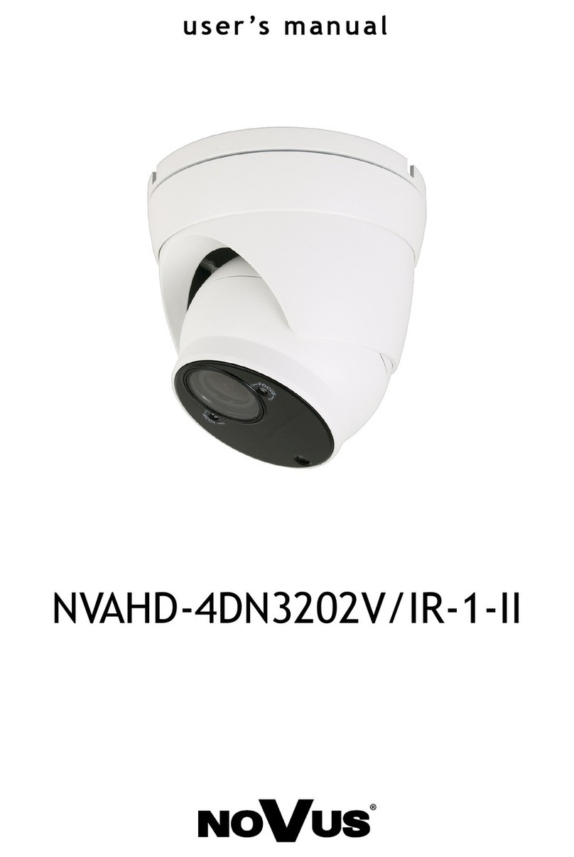
Automation Technology GmbH C4-2040-GigE User manual

C4-2040-GigE Camera
Hardware Reference
Manual
Rev 2.1
AT - Automation Technology GmbH

2 •C4-2040-GigE Camera Hardware Reference Manual Rev. 2.1
Table of Contents
Table of Contents 2
C4 Camera Series Overview 5
Introduction................................................................................................... 5
Measuring Principle........................................................................................ 5
Geometry 1 ....................................................................................... 6
Geometry 2 ....................................................................................... 6
Geometry 3 ....................................................................................... 7
Geometry 4 ....................................................................................... 7
The C4-2040-GigE Camera General Specifications .............................. 8
Mechanical Drawings ....................................................................... 10
The C4-2040-GigE CMOS Imager Specifications........................................... 11
C4-2040-GigE Camera Operational Reference 12
C4-2040-GigE Camera GenICam Features................................................... 12
DeviceControl .................................................................................. 12
ImageFormatControl ........................................................................ 12
AcquisitionControl ............................................................................ 13
CameraControl – AOIs (Areas Of Interest).......................................... 13
CameraControl – FIRControl ............................................................. 14
CameraControl – ModeAndAlgorithmControl ..................................... 14
CameraControl – ModeAndAlgorithmControl - AoiTracking ................. 15
CameraControl – ModeAndAlgorithmControl - AoiSearch.................... 15
CameraControl – ModeAndAlgorithmControl - ColumnEvaluationMask...... 15
CameraControl – SensorControl........................................................ 15
CameraControl – SensorControl – AdvancedSensorsettings.................. 15
CameraControl – DataOutput ........................................................... 16
CameraControl – Commands............................................................ 16
LightControl (partially available)......................................................... 16
CameraIO ....................................................................................... 17
TriggerControl.................................................................................. 18
TriggerControl – ResolverRS422 ........................................................19
TriggerControl – AutoStart................................................................. 19
TransportLayerControl....................................................................... 19
TransportLayerControl - GigEVision.................................................... 19
UserSetControl ................................................................................. 21
ChunkDataControl ........................................................................... 21
EventControl .................................................................................... 21

C4-2040-GigE Camera Hardware Reference Manual Rev. 2.1 •3
FileAccessControl ............................................................................. 21
The GenICam Features Configuration of C4-2040-GigE ................................ 23
The C4-2040-GigE Camera Algorithms......................................................... 26
The Image Mode (IMG) .................................................................... 26
The Maximum Intensity Profile Mode (MAX)......................................... 27
The Threshold Mode (TRSH) .............................................................. 28
The Center Of Gravity Mode (COG).................................................. 29
The FIR Peak Mode (FIR PEAK)........................................................... 30
The FIR Filter Function .................................................................................. 31
The High Dynamic Range 3D Feature (HDR-3D) of C4-2040-GigE.................. 32
Multiple Slope Function..................................................................... 32
Multi-Frame Readout Mode (NDR) ..................................................... 35
The Data Output Format of C4-2040-GigE ................................................... 37
The Data Channel Assignment DC0, DC1 and DC2............................ 37
The Output Frame Structure .............................................................. 39
Advanced AOI Functions .............................................................................. 43
C4-2040-GigE Camera Triggering ...............................................................44
Description of Profile Trigger Modes................................................... 44
Description of Modes for Triggering of Sequencer/Frame and Profile
Acquisition ....................................................................................... 46
The Chunk Data Mode of C4-2040-GigE...................................................... 48
General Description.......................................................................... 48
Payload Layout in Chunk Data Mode ................................................. 49
XML Descriptors and Id’s ................................................................... 50
Chunk Data Structure........................................................................ 51
The GigE-Vision Events of C4-2040-GigE .......................................... 52
C4-2040-GigE Camera Interface.................................................................. 53
The GigE Interface............................................................................ 53
The I/O & Power Interface................................................................. 53
The Illumination Control.................................................................... 54
Schematic of C4-2040-GigE digital inputs.......................................... 56
Schematic of C4-2040-GigE digital outputs........................................ 56
Description of LEDs........................................................................... 57
Integrated RS232 serial interface and Camera Boot Log....................... 58
Web service interface........................................................................ 60
The web service interface gives access to basic device and runtime
information aside from the common GenICam interface. It can be
accessed with an ordinary web browser, by simply typing the cameras
IP address into the browsers URL field, e.g.: http://169.254.64.2 for
the default camera IP address. A login window appears, as the
following figure shows. The static password “admin” gives access to
the camera service web interface........................................................ 60
The External C4-I/O-Panel (#202 182 006).................................................. 61
The C4 cables ............................................................................................. 64
Service Information 65
Document Revision ...................................................................................... 65
Product Information and Updates .................................................................. 66
Warranty Conditions .................................................................................... 67

4 •C4-2040-GigE Camera Hardware Reference Manual Rev. 2.1
© 2016 Automation Technology GmbH.
All rights reserved. No part of this document shall be reproduced, stored in a retrieval system, or
transmitted by any means, electronic, mechanical, photocopying, recording, or otherwise without
consent in writing from the owners, AT-Automation Technology GmbH.
Disclaimer
While care has been exercised in the preparation of this document to ensure that it is fully correct and
comprehensive, the owners assume no responsibility for errors or omissions. Neither is any liability
assumed for damages resulting from the use of the information contained herein. No license is
granted under any patents or patent right of AT – Automation Technology GmbH.
Trademarks
All nationally and internationally recognized trademarks and trade names are hereby acknowledged.
This document is subject to change without notification. All rights reserved.

C4-2040-GigE Camera Hardware Reference Manual Rev. 2.1 •5
C4 Camera Series Overview
Introduction
The C4 camera series is a revolutionary product family of intelligent high speed sensors. It is optimised
for 3D profile measurement by means of laser triangulation technique. The 3D profile extraction is
performed in the camera by using high performance Field Programmable Gate Array processors. At
the same time the 3D profile data is sent to the PC over a Gigabit Ethernet interface (GigE). This
extreme data reduction boosts the measuring speed to unprecedented levels without affecting the
performance of the connected image processing unit.
Measuring Principle
The C4 camera acquires height profiles and height images based on the laser triangulation principle.
According to this method a laser line is projected on the object from one direction. The C4 camera
views the object from another angle defining the triangulation geometry. The resulting sensor image is
evaluated by the C4 camera core and converted into a single height profile. By scanning the laser line
over the object a complete height image can be acquired.
The figures below demonstrate some typical triangulation geometries. The following notation is used in
the approximation of height resolution:
∆X= resolution along the laser line (lateral),
∆Y= resolution perpendicular to the laser line (longitudinal in the direction of motion),
∆Z= height resolution.

6 •C4-2040-GigE Camera Hardware Reference Manual Rev. 2.1
Geometry 1
The laser line is projected perpendicular to the object surface, while the camera views the object under
the triangulation angle α.
The height resolution can be approximated: ∆Z ≈∆X / sin(α)
Geometry 2
The camera views the object perpendicularly to its surface, while the laser line is projected under the
triangulation angle α.
The height resolution can be approximated: ∆Z ≈∆X / tan(α)
Scan direction
α
Scan direction
α
Y
Z
X
Y
Z
X

C4-2040-GigE Camera Hardware Reference Manual Rev. 2.1 •7
Geometry 3
The camera views the object under an angle α, while the laser line is projected under a different
angle β.
The height resolution can be approximated: ∆Z ≈∆X * cos(β) / sin(α+ β),
in case α= β(direct reflex) : ∆Z ≈∆X / 2* sin(α)
Geometry 4
The camera views the object under an angle α, while the laser line is projected under a different
angle βat the camera side.
The height resolution can be approximated: ∆Z ≈∆X * cos(β) / sin(α),
Scan direction
αβ
Scan direction
α
β
Y
Z
X
Y
Z
X

8 •C4-2040-GigE Camera Hardware Reference Manual Rev. 2.1
The C4-2040-GigE Camera General Specifications
Camera Controls
Synchronization Modes Free running, Triggered, Software Triggered
Exposure Modes Programmable, Pulse controlled
Shutter Modes Global Shutter
Digital Trigger Input 2 optoisolated inputs
5 V Level
VIL, logic “0” Voltage < 1.5 V
VIH, logic “1” Voltage > 3.5 V
24V Level (with C4-I/O-Panel only)
VIL, logic “0” Voltage < 7.5 V
VIH, logic “1” Voltage > 17.0 V
Digital Output 2 optoisolated outputs
VOL, logic “0” Voltage 0.6 V
VOH, logic “1” Voltage VCC (internal 20 kOhm pull-up)
IOH, logic “1” output current (internal 20 kOhm pull-up)
IOL, logic “0” output current 9 mA
Encoder Trigger Input RS422 Standard with 100 Ohm termination
Illumination Control Power 5 V DC, 200 mA, Modulation 20 kHz
Features
3D-Algorithms MAX, TRSH, COG, FIR PEAK
High Speed Acquisition Full frame: 340 fps
High Dynamic Range Imaging Multiple Slope, Multi-Frame Readout
Multiple AOIs / Laser lines Up to 8
Optical Interface
Lens Mount M42x1 with Back Focal Distance 6.52 mm
Adapter for C-Mount lens (must
be ordered separately)
Back Focal Distance 17.52 mm
Adapter for F-Mount lens with
Bajonett mount (must be
ordered separately)
Back Focal Distance 46.50 mm

C4-2040-GigE Camera Hardware Reference Manual Rev. 2.1 •9
Mechanical Interface
Camera Size 68 mm x 68 mm x 59 mm (with C-Mount adapter)
68 mm x 68 mm x 88 mm (with F-Mount adapter)
Mass (without optics) 340 g (C-Mount), 410 g (F-Mount)
Power connector 20-pin MDR
Ethernet connector RJ45
Illunimation control connector 5-pin M9
Electrical Interface
Input Voltage 10 – 24 V DC
Power consumption < 10 W
Operating Temperature 0 °C to +50 °C (non condensing)
Output Data Interface Gigabit Ethernet (IEEE 802.3)
Communication Protocol GigE Vision with GeniCam

10 •C4-2040-GigE Camera Hardware Reference Manual Rev. 2.1
Mechanical Drawings
C4-2040-GigE with C-Mount adapter:
C4-2040-GigE with F-Mount adapter:

C4-2040-GigE Camera Hardware Reference Manual Rev. 2.1 •11
The C4-2040-GigE CMOS Imager Specifications
Parameters Specifications
Sensitivity 16000 LSB / µJ / cm2@ 550 nm
Maximum Spectral Response 0.290 A / (W nm) @ 665 nm
Resolution 2048 x 1088 pixels
Pixel Size 5.5 µm x 5.5 µm
Sensor Size 11.264 mm x 5.984 mm, diagonal: 14.638 mm
Sensor Format 2/3”
Sensor ADC Resolution 10 bit
Sensor Dynamic Range 90 dB with HDR
Max. Internal Full-Frame Rate 340 fps
Max. External Full-Frame Rate
(limited due to GigE bandwidth)
50 fps
Effective Frame / Profile Rate at
Max. Row Length
Number of Rows Effective Frame / Profile Rate (Hz)
8
16
32
64
128
256
1088
30720
18778
10362
5464
2809
1424
340
*with Frame Overhead Time (FOT)=2

12 •C4-2040-GigE Camera Hardware Reference Manual Rev. 2.1
C4-2040-GigE Camera
Operational Reference
C4-2040-GigE Camera GenICam Features
DeviceControl
Name Rev. Interface Access Description
DeviceVendorName 1.0 IString R The name of the device vendor.
DeviceModelName 1.0 IString R The name of the device model.
DeviceManufacturerInfo 1.0 IString R Additional info from manufacturer about this device.
DeviceVersion 1.0 IString R A string identifying the version of the device.
DeviceSerialNumber 1.0 IString R Serial number of the camera
DeviceFirmwareVersion 1.0 IString R Version of firmware/software.
DeviceUserID 1.0 IString R/W User-programmable device identifier.
DeviceScanType 1.0 IEnumeration R Show the camera type:
- Areascan
DeviceReset 1.0 ICommand W Resets and reboots the device immediately.
DeviceRegistersStreamingStart 1.2 ICommand W Announces the start of registers streaming without
immediate checking for consistency.
DeviceRegistersStreamingEnd 1.2 ICommand W Announces the end of registers streaming and
perform validation for registers consistency before
activating them. This will also update the
DeviceRegistersValid flag.
DeviceRegistersCheck 1.2 ICommand W Performs an explicit register set validation for
consistency.
DeviceRegistersValid 1.2 IBoolean R Indicates whether the current register set is valid and
consistent.
DeviceTemperatureSelector AT IEnumeration R/W Select temperature sensor:
- Mainboard
- Sensor
DeviceTemperature AT IFloat R Device temperature in degrees Celsius (°C).
DeviceMaxThroughput 1.2 IInteger R Maximum Bandwidth of data in Bytes/sec.
ImageFormatControl
Name Rev. Interface Access Description
SensorWidth 1.0
IInteger R Width of sensor (effective pixels)
SensorHeight 1.0
IInteger R Height of sensor (effective pixels)
Width 1.0
IInteger R/W Width of Image/Area Of Interest.
Height 1.0
IInteger R/W Height of Image/Area Of Interest.
In Image-Mode writing this manipulates AOI[0].height
PixelFormat 1.0
IEnumeration R/W Format of the image pixels. For more details, see the
Pixel Format description chapter.
- Mono8
- Mono16
ReverseX 1.0
IBoolean R/W When set to true, this parameter flips the sensor
image horizontally
ReverseY 1.0
IBoolean R/W When set to true, this parameter flips the sensor

C4-2040-GigE Camera Hardware Reference Manual Rev. 2.1 •13
Name Rev. Interface Access Description
image vertically.
OffsetX 1.0 IInteger R
X Offset of AOI (fixed to zero)
TestPatternGeneratorSelector 1.0
IEnumeration R Selects which test pattern generator is controlled by
the TestPattern feature.
TestPattern 1.0
IEnumeration R/W Selects the type of test pattern that is generated by
the device as image source.
- Off
- GreyHorSensorColumnPattern
- GreyVertSensorColumnPattern
LinePitch 1.0
IInteger R Distance between consecutive lines in bytes.
PixelDynamicRangeMin 1.0
IInteger R Minimum pixel value sent by the camera.
PixelDynamicRangeMax 1.0
IInteger R Maximum pixel value sent by the camera.
AcquisitionControl
Name Rev. Interface Access Description
AcquisitionStart 1.0 ICommand W Issues the START command. This starts the
acquisition.
AcquisitionStop 1.0 ICommand W Issues the STOP command. This stops the
acquisition.
AcquisitionMode 1.0 IEnumeration R/W Defines the type of acquisition:
- SingleFrame
- MultiFrame
- Continuous
AcquisitionAbort 1.0 ICommand W Issues the ABORT command. This immediately
aborts the acquisition without completing the current
frame.
AcquisitionFrameCount 1.0 IInteger R/W Number of frames to be acquired in MultiFrame
acquisition mode. The minimum allowable value is 1.
AcquisitionFrameRateAbs 1.2 IFloat R The frame rate of the imager. Absolute units are in
Hz.
AcquisitionStatusSelector 1.2
IEnumeration R/W Selector for AcquisitionStatus to read:
- AcquisitionTriggerWait
- AcquisitionActive
- AcquisitionTransfer
- FrameTriggerWait
AcquisitionStatus[AcquisitionStatus
Selector]
1.2
IBoolean R Status of the selected acquisition flag
AcquisitionMaxBufferedFrameCoun
t
AT IInteger R Maximum number of buffered frames
ExposureMode 2.2 IEnumeration R Sets the operation mode of the exposure:
1 : Timed
2 : MultiSloped
3 : MultiExposed
MultiSloped and MultiExposed refers to HDR-3D
ExposureTime 2.2 IInteger R/W Sets the overall exposure time when ExposureMode
is Timed or MultiSloped in microseconds (µs).
This parameter is the standardized equivalent to
ExposureTimeAbs
ExposureSlopeKneepointCount AT IInteger R/W The number of additional exposure slopes used for
Multi-Slope exposure
0: SingleSlope
1: DualSlope
2: TripleSlope
ExposureSlopeKneePointSelector AT IInteger R/W Selects the parameters for controlling a kneepoint
during multi-slope exposure
ExposureSlopeDuration AT IFloat R/W The exposure duration (in percentage of
ExposureTime) for determining a kneepoint during
multi-slope exposure
ExposureSlopeThreshold AT IFloat R/W The threshold for determining a kneepoint during
multi-slope exposure. Setting this value to 100% will
effectively disable this kneepoint
CameraControl – AOIs (Areas Of Interest)
Name Rev. Interface Access Description
MaxNumAOIs AT IInteger R Maximum number of AOIs.
NumAOIs AT IInteger R/W Number of used AOIs.
ImageModeAoiSelector AT IInteger R/W Selects the AOI to show in image mode

14 •C4-2040-GigE Camera Hardware Reference Manual Rev. 2.1
AoiSelector AT IInteger R/W Selects which AOI to control
AoiHeight AT IInteger R/W
Number of sensor rows in AOI
AoiOffsetY AT IInteger R/W
Offset distance in rows between the first row of AOI
and the first row of sensor chip
AoiThreshold AT IInteger R/W
Intensity threshold value for selected AOI.
CameraControl – FIRControl
Name Rev. Interface Access Description
FIR AT IBoolean R/W True: Enables the FIR filter
False: Disables the FIR filter
FIRMode AT IEnumeration R/W Selection of the FIR mode
-Derivative
-Smoothing
FIRCoef AT IEnumeration R/W Selection of the FIR filter coefficients
- SG5
- SG7
- SG9
- AV5 (Smoothing mode only)
- AV7 (Smoothing mode only)
- AV9 (Smoothing mode only)
- Custom
FIRGain AT IInteger R/W Gain of FIR filter
FIRCorrection AT IBoolean R/W
True: The effect of filter index mismatch in 3D mode
is cancelled
False: No correction is performed
FIRC0 AT IFloat R/W Value of FIR coefficient #0
FIRC1 AT IFloat R/W Value of FIR coefficient #1
FIRC2 AT IFloat R/W Value of FIR coefficient #2
FIRC3 AT IFloat R/W Value of FIR coefficient #3
FIRC4 AT IFloat R/W Value of FIR coefficient #4
CameraControl – ModeAndAlgorithmControl
Name Rev. Interface Access Description
CameraMode AT IEnumeration R/W Selects the camera mode or algorithm:
- Image
- FIRPeak
- CenterOfGravity
- Threshold
- MaximumIntensity
ProfilesPerFrame AT IInteger R/W This feature represents the number of Profiles per
Frame in 3D-Mode expelled by the camera.
AbsOffsetPos AT IBoolean R/W True: Position values are referenced to the first row
of sensor chip (absolute position).
False: Position values are referenced to the first row
of AOI.
NumSubPixel AT IInteger R/W Number of subpixel bits of COG/FIR-PEAK output
(0-6).
TrshFirstFalling AT IBoolean R/W Stop the position calculation along an AOI column,
as soon as the falling edge of a Gauss curve is
detected.
TrshFirstZeroCrossing AT IBoolean R/W Stop the position calculation along an AOI column,
as soon as the first zero-crossing of intensity first
derivative is detected (FIR-PEAK).
MinTrshValidation AT IBoolean R/W Validate the FIR-PEAK result by checking for
symmetry in the derived intensity signal.
PosValidationEn AT IBoolean R/W Enable validation of position value of a Gauss curve
using tolerances for width and sum of intensity.
Perform validation during scan of image column and
immediately after detecting a Gauss falling edge.
Clear the result, if the position value is invalid.
ClearInvalidPos AT IBoolean R/W Enable validation of position value using tolerances
for width and sum of intensity. Perform validation at
the end of scan of image column. Invalid position
values are set to zero in all DCs.
ValidationWidthMin AT IInteger R/W Minimum width of valid intensity distribution in 3D-
mode.
ValidationWidthMax AT IInteger R/W Maximum width of valid intensity distribution in 3D-
mode.
ValidationSumMin AT IInteger R/W Minimum sum of intensity of valid intensity

C4-2040-GigE Camera Hardware Reference Manual Rev. 2.1 •15
Name Rev. Interface Access Description
distribution in 3D-mode.
ValidationSumMax AT IInteger R/W Maximum sum of intensity of valid intensity
distribution in 3D-mode.
CameraControl – ModeAndAlgorithmControl - AoiTracking
Name Rev. Interface Access Description
AoiTrackingEnable AT IBoolean R/W True: AOI-Tracking mode is enabled
False: AOI-Tracking mode is disabled
AoiTrackingMinNumPixel AT IInteger R/W Minimum number of required pixel (one pixel per
column) to start AOI tracking algorithm
AoiTracking_P AT IFloat R/W Proportional gain of PID controller
AoiTracking_I AT IFloat R/W Integral gain of PID controller
AoiTracking_D AT IFloat R/W Derivative gain of PID controller
AoiTrackingUpdateRate AT IInteger R/W Update frequency of tracking algorithm (Hz)
AoiTrackingSensorWriteTimeout AT IInteger R/W AOI tracking senosr write timeout in microseconds
(µs)
CameraControl – ModeAndAlgorithmControl - AoiSearch
Name Rev. Interface Access Description
AoiSearchEnable AT IBoolean R/W True: AOI-Search mode is activated
False: AOI-Search mode is disabled
AoiSearchHeight AT IInteger R/W Height of search AOI
AoiSearchOffsetY AT IInteger R/W Vertical offset from the origin to the search AOI
CameraControl – ModeAndAlgorithmControl - ColumnEvaluationMask
Name Rev. Interface Access Description
ColRangeStart AT IInteger R/W Column start index
ColRangeEnd AT IInteger R/W Column end index
ColRangeEnableCommand
AT ICommand W Enable all columns from RangeStart to RangeEnd
ColRangeDisableCommand AT ICommand W Disable all columns from RangeStart to RangeEnd
ColRangeActivate AT ICommand W Activate complete ColumnEvaluationMask and write
data into flash memory
CameraControl – SensorControl
Name Rev. Interface Access Description
SensorFrameCounter AT IInteger R Sensor frame counter.
SensorReadoutTime AT IInteger R Sensor Readout Time in µs.
ExposureTimeAbs AT IInteger R/W Sensor integration time in µs.
FramePeriode AT IInteger R/W Time between two frames in µs.
FrameRate AT IFloat R Frame rate in Hz
MultipleSlopeMode AT IEnumeration R/W MultipleSlope Mode:
- SingleSlope
- DualSlope
- TripleSlope
DualSlopeTime AT IInteger R/W DualSlopeTime in % of sensor integration time
TripleSlopeTime AT IInteger R/W TripleSlopeTime in % of sensor integration time
NumberOfNDRFrames AT IInteger R/W Number of NDR frames.
NDRMode AT IEnumeration R/W Multi-Frame Readout Mode (NDR):
- Off
- On
NDRExposureTimeAbs_1 AT IInteger R/W NDR exposure time 1.
NDRExposureTimeAbs_2 AT IInteger R/W NDR exposure time 2.
NDRExposureTimeAbs_3 AT IInteger R/W NDR exposure time 3.
NDRExposureTimeAbs_4 AT IInteger R/W NDR exposure time 4.
CameraControl – SensorControl – AdvancedSensorsettings
Name Rev. Interface Access Description
LineStartSyncTrigger AT IBoolean R/W Enable line start synchronous frame trigger
GainPGA AT IEnumeration R/W PGA Gain Voltage
GainADC 1.2 IEnumeration R/W ADC Gain Voltage
Vlow2 AT IInteger
R/W Voltage for defining exposure kneepoint 1 in the

16 •C4-2040-GigE Camera Hardware Reference Manual Rev. 2.1
range of 127 (zero intensity) down to 64
(saturation).
Vlow3 AT IInteger
R/W Voltage for defining exposure kneepoint 2 in the
range of 127 (zero intensity) down to 64
(saturation).
Vramp1 AT IInteger
R/W Start voltage first ramp for column FPN
correction
Vramp2 AT IInteger
R/W Start voltage second ramp for column FPN
correction
BlackSunControl AT IInteger R/W Control the black sun protection level (0 = not
supported, 64 to 127 black sun protection level)
FOT AT IInteger
R/W Frame Overhead Time
DummyRows AT IInteger
R/W Dummy rows
VresLow AT IInteger
R/W VresLow
CameraControl – DataOutput
Name Rev. Interface Access Description
EnableDC2 AT IBoolean R/W Activates the output data channel DC2.
EnableDC1 AT IBoolean R/W Activates the output data channel DC1.
EnableDC0 AT IBoolean R/W Activates the output data channel DC0.
EnableDC0Shift AT IBoolean R/W Right shift twice the intensity value in DC0, when
PixelFormat is Mono8.
EnableDC1TrshWidth AT IBoolean R/W Controls the output in channel DC1, when TRSH
algorithm is selected:
True: DC1 outputs the laser line width.
False: DC1 outputs the left edge position.
EnableDC1Option AT IBoolean R/W Controls the output in channel DC1.
When CameraMode = CenterOfGravity:
True: DC1 outputs the laser line width.
False: DC1 outputs the left edge position.
When CameraMode = FIRPeak:
True: DC1 outputs the maximum value of
intensity first derivative.
False: DC1 outputs the index of next sensor row
to the left of zero-crossing
EnableDC1Flags AT IBoolean R/W When in 16 bit mode, the bits 12-15 of output
channel DC1 contain additional algorithm flags
EnableDC2TrshSP AT IBoolean R/W Controls the output in channel DC2, when TRSH
algorithm is selected:
True: DC2 outputs the position value with 1
subpixel.
False: DC2 outputs the right edge position.
CameraControl – Commands
Name Rev. Interface Access Description
StartPulse AT ICommand W Send Start pulse.
StopPulse AT ICommand W Send Stop pulse.
TriggerPulse AT ICommand W Send Trigger pulse.
RstFrameCnt AT ICommand W Reset frame counter to zero.
SearchAoi AT ICommand W Fit AOI to laser line position. Supports only one
AOI
LightControl (partially available)
Name Rev. Interface Access Description
LightSelector AT IEnumeration R/W Select a light device to control
LightInterface AT IEnumeration R/(W) Select the interface for light device to control
LightSource AT IEnumeration R/W Select which source signal to use to activate the
selected light device:
0: Off
1: On
3: ExposureActive
LightBrightness AT IFloat R/W Control the laser power from 0 to 100 percent (%)
using increments of 0.1 %. This value is
translated to the equivalent analog modulation-
voltage value for the selected light device. The

C4-2040-GigE Camera Hardware Reference Manual Rev. 2.1 •17
required minimum/maximum voltage values are
deposited as part of firmware implementation for
each of the supported light devices.
LightModulationVoltage AT IFloat R Return the actual modulation voltage for the
selected light brightness value.
LightMonitorVoltage AT
IFloat R Light monitor voltage, former VoltageIn (AI). Not
supported for all light devices.
LightConnectionStatus AT
IEnumeration R Return the selected light device status:
0: Ready
Selected device is ready.
1: Sensing
Camera is attempting to establish a connection
with the newly selected light device or is currently
reconnecting after a disconnection.
2: NoConnect
System failed to initialize connection for selected
device.
8: SystemError
Selected light device has indicated an internal
system error. The specific error for this indication
can be retrieved from the
‘LightModuleErrorStatus’ register, if supported for
this light device.
9: DataError
Indicates a data transmission error for the latest
transmission between camera and light device.
This flag indicates that the previous read register
value has been corrupted, so that data should be
re-read before usage.
16: SystemWarning
Selected light device has indicated an internal
system warning. The specific warning for this
indication can be retrieved from the
‘LightModuleWarningStatus’ register, if supported
for this light device.
LightModelName AT
IString R Return the light model name as string.
LightSerialNumber AT
IString R Return the light device serial number.
LightFirmwareVersion AT
IString R Return the light firmware version as string.
LightHardwareVersion AT
IString R Return the light hardware version as string.
LightOperatingTime AT
IInteger R Return the laser diodes accumulated operating
hours.
LightOperatingCurrent AT
IInteger R Return the light device operating current in mA.
LightTemperatureSelector AT
IEnumeration R/W Select the device specific temperature source:
0: Diode
1: Housing
2: DiodeLowLimit
3: DiodeHighLimit
LightTemperature AT
IFloat R Show the selected temperature value in degrees
Celsius (C).
LightModuleErrorStatus AT
IInteger R Return the light device error status as
hexadecimal value. Note: This feature is currently
only supported for the ‘ZLaser ZFSM RS232’ light
device. The returned value is equal to the ZFSM
error code retrieved via the
GET_OPERATION_STATUS command. Please
see the ZFSM manufacturer data sheet for more
details.
LightModuleWarningStatus AT
IInteger R Return the light device warning status as
hexadecimal value. Note: This feature is currently
only supported for the ‘ZLaser ZFSM RS232’ light
device. The returned value is equal to the ZFSM
warning code retrieved via the
GET_OPERATION_STATUS command. Please
see the ZFSM manufacturer data sheet for more
details.
CameraIO
Name Rev. Interface Access Description
Input1 AT IEnumeration R Lists the input signals available for IN1:
- Input1_Unused.
- Input1_FrameStart

18 •C4-2040-GigE Camera Hardware Reference Manual Rev. 2.1
Name Rev. Interface Access Description
- Input1_EnableFrame
- Input1_Trigger
Input2 AT IEnumeration R Lists the input signals available for IN2:
- Input2_Unused.
- Input2_StopFrame
- Input2_Trigger
Output1 AT IEnumeration RW Selects the output signal for OUT1:
Symbolic Value
- Out1_IntegrationActive
- Out1_SequencerActive
- Out1_IntegrationDualSlopeActive
- Out1_IntegrationTripleSlopeActive
- Out1_High
- Out1_Low
- Out1_InternalTrigger
- Out1_SequencerTriggerActive
Integer Value
0
1
2
3
4
5
6
7
Output2 AT IEnumeration RW Selects the output signal for OUT2:
Symbolic Value
- Out2_IntegrationActive,
- Out2_IntegrationDualSlopeActive
- Out2_IntegrationTripleSlopeActive
- Out2_High
- Out2_Low
- Out2_TriggerOverrun
- Out2_ResolverCountDir
- Out2_TriggerBusy
- Out2_AutoStart
Integer Value
0
1
2
3
4
5
6
7
8
Input1Level AT IEnumeration R The voltage level of IN1:
- Input1Level_High
- Input1Level_Low
Input2Level AT IEnumeration R The voltage level of IN2:
- Input2Level_High
- Input2Level_Low
RS422ChannelALevel AT IEnumeration R Voltage level of RS422 Channel A:
- RS422ChannelALevel_High
- RS422ChannelALevel_Low
RS422ChannelBLevel AT IEnumeration R Volatge level of RS422 Channel B
- RS422ChannelBLevel_High
- RS422ChannelBLevel_Low
LaserPower AT IFloat R/W Sets the output analog voltage of illumination control
in the range 0.0-5.0 V DC (corresponds to 0...100%)
TurnLaserOn AT IBoolean R/W Laser turn on/off.
TurnLaserOnAuto AT IBoolean R/W Laser turn on automatically during sensor integration.
VoltageIn AT IFloat R Reads the input analog voltage of illumination control
(range 0.0-5.0 V DC)
Output1MinPulseWidth AT
IInteger
R/W Output1 minimum pulse width in microseconds (µs)
Output2MinPulseWidth AT
IInteger
R/W Output2 minimum pulse width in microseconds (µs)
Output1Delay AT
IInteger
R/W Output1 delay in microseconds (µs)
Output2Delay AT
IInteger
R/W Output2 delay in microseconds (µs)
Output1Invert AT
IBoolean
R/W True: Output1 inverted
False: Output1 not inverted
Output2Invert AT
IBoolean
R/W True: Output1 inverted
False: Output1 not inverted
TriggerControl
Name Rev. Interface Access Description
SequencerMode AT IEnumeration R/W Selects the start trigger mode:
- FreeRun
- StartStopCameraInput12
- StartCameraInput1
- GateCameraInput1
- StartStopCameraInput12Event
- AutoStart
ProfileTriggerMode AT IEnumeration R/W Selects the profile trigger mode:
- FreeRun
- CameraInput1
- CameraInput2
- EncoderResolverInterfaceRS422.
TriggerOverrun AT IBoolean R Trigger Overrun Flag.
ClearTriggerOverrun AT ICommand W Command to clear the trigger overrun flag.

C4-2040-GigE Camera Hardware Reference Manual Rev. 2.1 •19
TriggerControl – ResolverRS422
Name Rev. Interface Access Description
TriggerDivider AT IInteger R/W Trigger divider.
TriggerCoord AT IInteger R Resolver trigger coordinates
TriggerDirectionMode AT IBoolean R/W A sensor image is triggered when the internal pulse
counter is countdown to 0. Upon start of acquisition,
the initial value of pulse counter is equal to trigger
divider.
This parameter controls the behaviour of the pulse
counter:
True: The pulse counter is decreased and
countdown to 0, when resolver pulses are
generated from both moving directions (forwards
and backwards).
False: The pulse counter is decreased and
countdown to 0, when resolver pulses are
generated from one moving direction only (e.g.
forwards). In that case, pulses corresponding to the
opposite moving direction (e.g. backwards) will
increase the pulse counter.
TriggerReverseDirection AT IBoolean R/W Reverse the pulse count direction.
TriggerDividerLoadAtStart AT IBoolean R/W Loads the value of trigger divider into the pulse
counter, when start trigger occurs.
TriggerSingleChannelMode AT IEnumeration R/W Enables trigger mode using single channel resolver:
- Disabled
- EnableIn1 (Enable A/IN1)
- EnableIn2 (Enable B/IN2)
LoadTriggerDivider AT ICommand W Command to load the value of trigger divider into
the pulse counter.
ClearTriggerCoord AT ICommand W Reset trigger coordinate counter
ResetTriggerCoordZeroPos AT IEnumeration R/W Reset the Trigger Coordinate/Counter at Encoder
Zero Position (Index, Z-Channel)
- Off (Index Z Off)
- On (Index Z On)
TriggerCoordinateCountAlways AT IBoolean R/W Controls when trigger coordinates shall be counted:
True: Trigger coordinates are counted always
False: Trigger coordinates are counted only during
image acquisition
UseAlternateResolverInputs AT IBoolean R/W True: Use IN1/IN2 instead of A/B as encoder input
False: Use A/B as encoder input
UseAlternateResolverInputsInv
erted
AT IBoolean R/W True: Invert encoder input over IN1/IN2
False: Do not invert encoder input over IN1/IN2
TriggerControl – AutoStart
Name Rev. Interface Access Description
AutoStartThreshold AT IInteger R/W Defines the position within AOI to trigger the
AutoStart. Valid values are:
When AbsolutePosition = FALSE : 0 - AOI-Height
When AbsolutePosition = TRUE : 0 - Sensor-Height
AutoStartNumPixel AT IInteger R/W
Minimum number of valid laser positions within AOI
required to trigger the Autostart
AutoStartOption AT IEnumeration R/W
PosLessThanAutostartThreshold: Start when laser
position is less-than AutoStartThreshold
PosGreaterThanAutostartThreshold: Start when
laser position is greater-than AutoStartThreshold
AutoStartBufferOption AT IEnumeration R/W
Defines whether the history buffer should be
transmitted as first frame or not
-none
-HistoryBuffer
TransportLayerControl
Name Rev. Interface Access Description
PayloadSize 1.0 IInteger R PayloadSize provides the number of bytes transferred
for each image on the stream channel
TransportLayerControl - GigEVision
Name Rev. Interface Access Description

20 •C4-2040-GigE Camera Hardware Reference Manual Rev. 2.1
Name Rev. Interface Access Description
GevVersionMajor 1.2 IInteger
R This field represents the major version of the GigE
Vision specification supported by this device
GevVersionMinor 1.2 IInteger
R This field represents the minor version of the GigE
Vision specification supported by this device
GevDeviceModeIsBigEndian 1.2
IBoolean R This represents the endianess of bootstrap registers
(FALSE: Little-endian device TRUE: Big-endian
device)
GevDeviceModeCharacterSet 1.2
IEnumeration R This feature represents the character set of all boot
strap strings:
- CharacterSet_UTF8
GevInterfaceSelector 1.2
IEnumeration R Indicates the index of the network interface to
configure:
- EnumEntry_GevInterfaceSelector_Interface_0
GevMACAddress 1.2
IInteger R 48-bit MAC address of the selected interface
GevSupportedIPConfigurationLLA 1.2
IBoolean
R/W Indicate if LLA (Auto-IP) is supported by the selected
interface
GevSupportedIPConfigurationDHC
P
1.2
IBoolean
R/W Indicate if DHCP is supported by the selected
interface
GevSupportedIPConfigurationPers
istentIP
1.2
IBoolean
R/W Indicate if Persistent IP is supported by the selected
interface
GevCurrentIPConfigurationLLA 1.2
IBoolean
R This feature indicates if Link Local Address IP
configuration scheme is activated on the given
network interface
GevCurrentIPConfigurationDHCP 1.2
IBoolean
R This feature indicates if DHCP Address IP
configuration scheme is activated on the given
network interface
GevCurrentIPConfigurationPersist
entIP
1.2
IBoolean
R This feature indicates if PersistentIP IP configuration
scheme is activated on the given network interface
GevCurrentIPAddress 1.2
IInteger R IP address of the selected interface
GevCurrentSubnetMask 1.2
IInteger R Subnet mask of the selected interface
GevCurrentDefaultGateway 1.2
IInteger R Default gateway of the selected interface
GevPersistentIPAddress 1.2
IInteger R/W Persistent IP address for the selected interface
GevPersistentSubnetMask 1.2
IInteger R/W Persistent subnet mask for the selected interface
GevPersistentDefaultGateway 1.2
IInteger R/W Persistent default gateway for the selected interface
GevLinkSpeed 1.2 IInteger R Link speed in Mbps.
GevFirstURL 1.2
IString R NULL-terminated string providing the first URL to the
XML device description file
GevSecondURL 1.2
IString R
NULL-terminated string providing the second URL to
the XML device description file
GevNumberOfInterfaces 1.2
IInteger R
Indicates the number of physical network interfaces on
this device
GevMessageChannelCount 1.2
IInteger R
Indicates the number of message channels supported
by this device
GevStreamChannelCount 1.2
IInteger R
Indicates the number of stream channels supported by
this device
GevSupportedOptionalCommands
UserDefinedName
1.2
IBoolean
R
Indicates if the User-defined Name register is
supported
GevSupportedOptionalCommands
SerialNumber
1.2
IBoolean
R
Indicates if the Serial Number register is supported
GevSupportedOptionalCommands
EVENTDATA
1.2
IBoolean
R
Indicates if EVENTDATA_CMD and
EVENTDATA_ACK are supported
GevSupportedOptionalCommands
EVENT
1.2
IBoolean
R
Indicates if EVENT_CMD and EVENT_ACK are
supported
GevSupportedOptionalCommands
PACKETRESEND
1.2 IBoolean
R
Indicates if PACKETRESEND_CMD is supported
GevSupportedOptionalCommands
WRITEMEM
1.2
IBoolean
R
Indicates if WRITEMEM_CMD and WRITEMEM_ACK
are supported
GevSupportedOptionalCommands
Concatenation
1.2
IBoolean
R
Indicates if multiple operations in a single message
are supported
GevHeartbeatTimeout 1.2
IInteger R/W
Current heartbeat timeout in milliseconds
GevTimestampTickFrequency 1.2
IInteger R
64-bit value indicating the number of timestamp clock
tick in 1 second
GevTimestampControlLatch 1.2
ICommand
R
Latches the current timestamp value of the device
GevTimestampControlReset 1.2
ICommand
R
Resets the timestamp count of the device
GevTimestampValue 1.2 IInteger R Latched 64-bit value of the timestamp. Value must first
be latched using GevTimestampControlLatch.
GevStreamChannelSelector 1.2
IInteger
R/W
Indicate which stream channel to configure
GevSCPInterfaceIndex 1.2
IInteger
R
Index of network interface
GevSCPSPacketSize 1.2
IInteger
R/W
The size of the stream packet to send on this channel
GevSCPD 1.2
IInteger
R/W
Delay (in timestamp counter unit) to insert between
Table of contents
Other Automation Technology GmbH Digital Camera manuals
