SSR Terminal Blocks
A-55
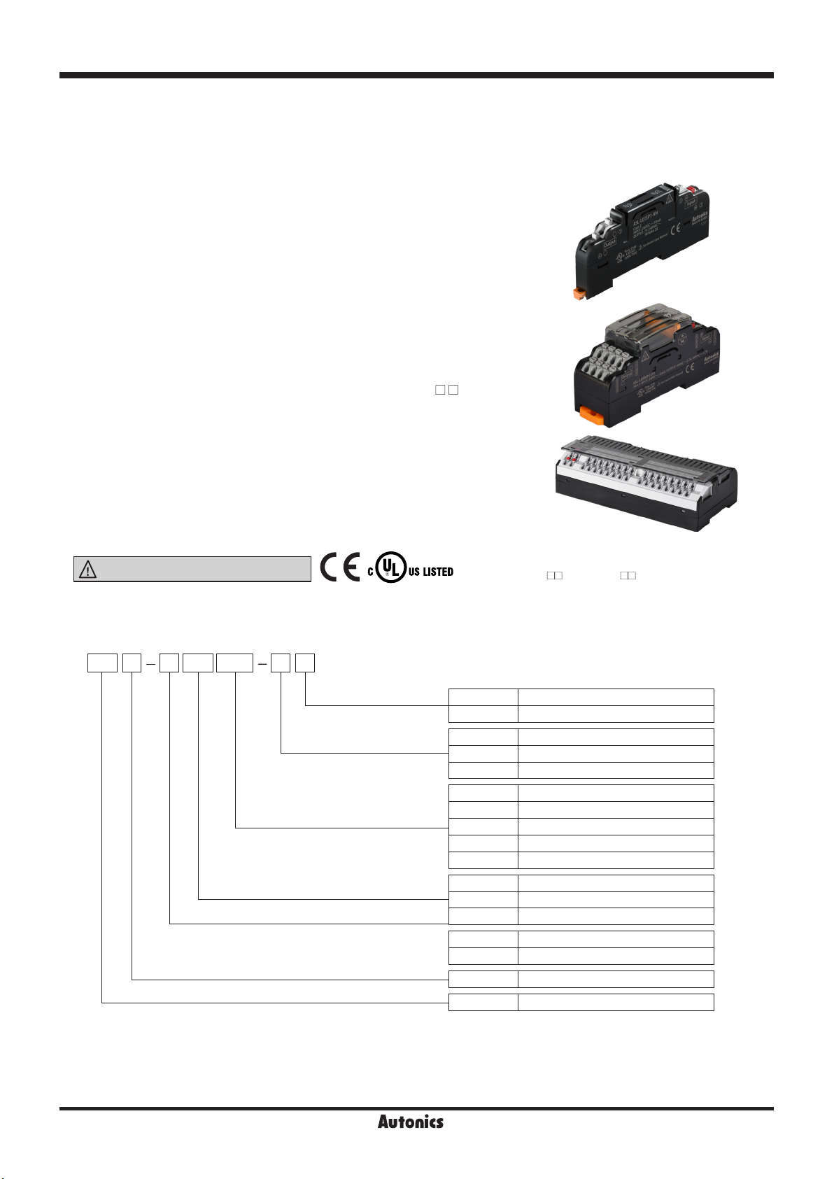
ABS Series
ABL Series
ASL Series
Power Relay
SSR
I/O Terminal Blocks
Interface
Terminal Blocks
Common
Terminal Blocks
Sensor Connector
Terminal Blocks
Relay
Terminal Blocks
I/O Cables
Connector Type
Cables
Open Type
Cables
Others
-|Transparent setting guide|-
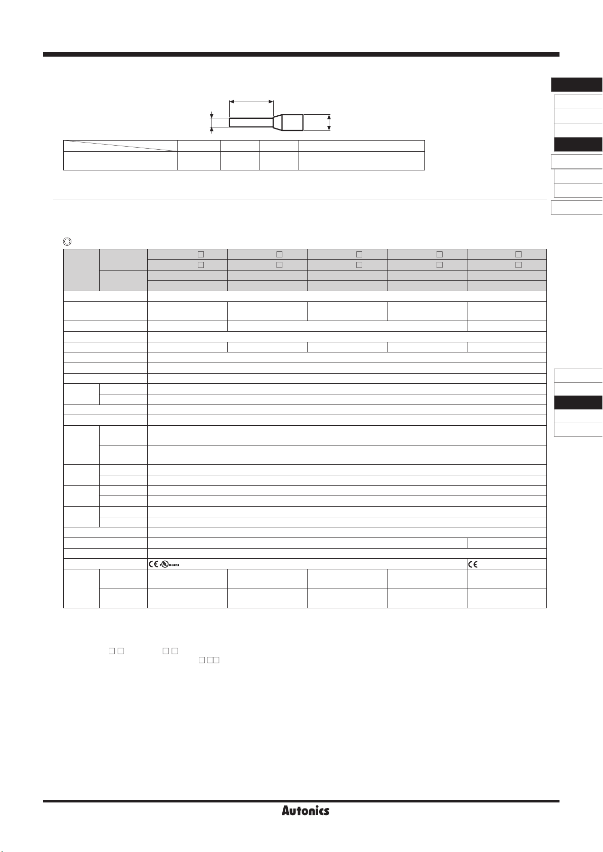
▣Crimp Terminal Specication
(unit: mm)
ABCApplicable wire
End Sleeve (ferrule terminal)
crimp terminal 10 to 12.0 ≤ 2.0 ≤ 4.1 AWG22-16 (0.30 to 1.25mm2)
A
C
B
▣Specications
1-point, 4-point
Model
1-point ASL-L01MP0- N ASL-L01SP0- N ASL-L01SP1- N ASL-L01SR0- N ASL-L01ST0- N
ASL-L01MP0- Y ASL-L01SP0- Y ASL-L01SP1- Y ASL-L01SR0- Y ASL-L01ST0- Y
4-point ASL-L04MP0-UN ASL-L04SP0-UN
- -
ASL-L04ST0-UN
ASL-L04MP0-UY
※1
ASL-L04SP0-UY
※1
- -
ASL-L04ST0-UY
※1
Power supply 24VDCᜡ±10%
Rated load voltage &
current※2
60VACᜠ/DCᜡ
50/60Hz 2.7A
75-240VACᜠ
50/60Hz 1A
75-240VACᜠ
50/60Hz 2A
24-240VACᜠ
50/60Hz 2A
24-240VACᜠ
50/60Hz 1A
Current consumption
※
3
≤ 3mA ≤ 18mA ≤ 10mA
Output type 1a contact SSR output
Applied SSR AQZ202D [Panasonic]
AQG12124 [Panasonic] AQG22124 [Panasonic]
G3MC-202P [Omron]
SN-24A01C [Fujitsu]
Terminal type Screwless
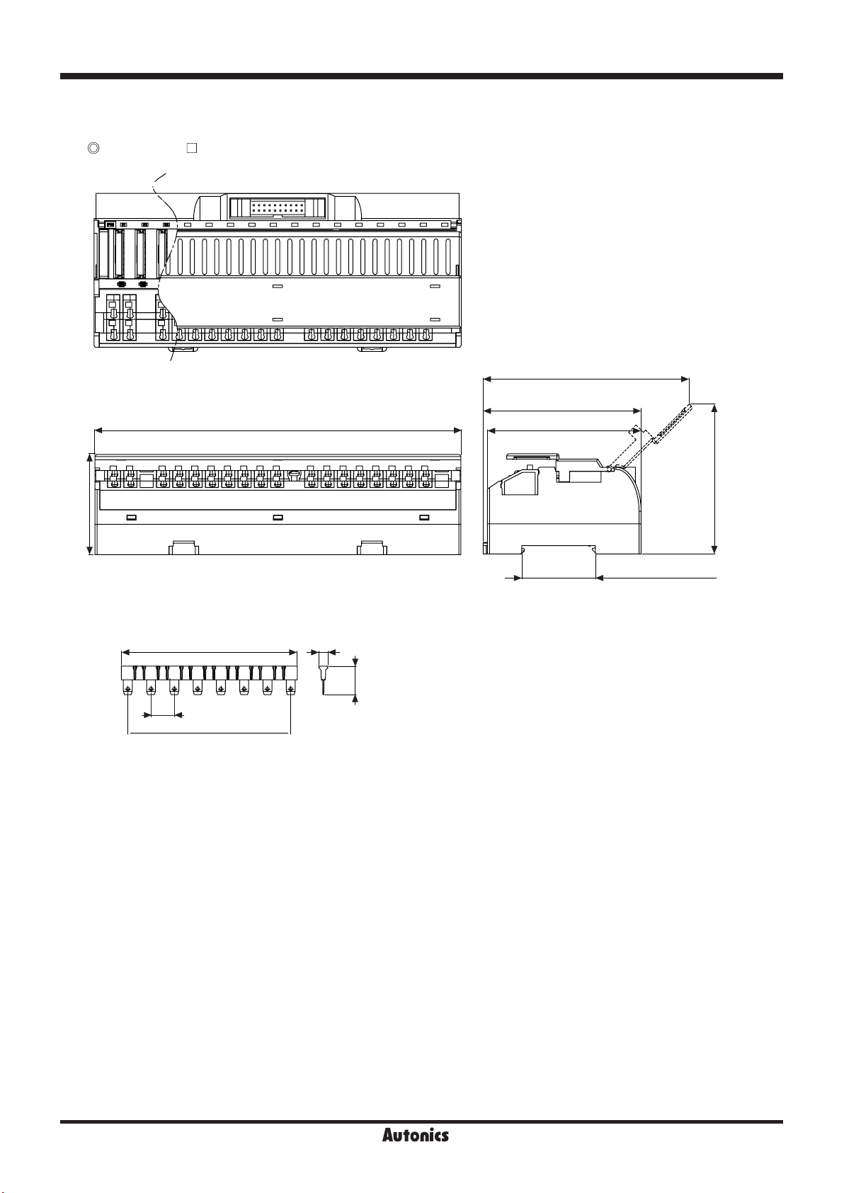
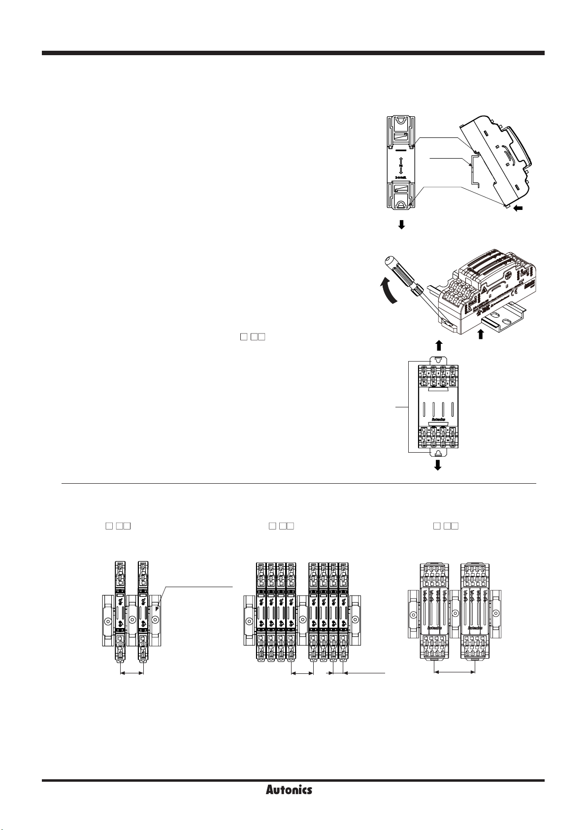
Terminal pitch 1-point: 9.0mm (arranging over 2 units)/4-point: 5.0mm
Operation Indicator Blue LED
Applied
cable
Solid wire Ø0.6 to Ø1.25mm (60℃ only)
Stranded wire
※
4
AWG22-16 (0.30 to 1.25mm2) (60℃ only)
Stripped wire length 8 to 10mm
Insulation resistance 1-point: ≥ 1,000MΩ (at 500VDC megger)/4-point: ≥ 1,000MΩ (at 500VDC megger)
Insulation
resistance
Between
coil-contact 2,500VAC 50/60Hz for 1 minute
Between
same contacts
※5
1,000VAC 50/60Hz for 1 minute
Vibration Mechanical 0.75mm amplitude at frequency of 10 to 55Hz (for 1 min) in each X, Y, Z direction for 2 hours
Malfunction 0.75mm amplitude at frequency of 10 to 55Hz (for 1 min) in each X, Y, Z direction for 10 minutes
Shock Mechanical 1,000m/s2 (approx. 100G) in each X, Y, Z direction for 3 times
Malfunction 100m/s2 (approx. 10G) in each X, Y, Z direction for 3 times
Environ-
ment
Ambient temp.
-15 to 55℃, storage: -25 to 65℃
Ambient humi.
35 to 85%RH, storage: 35 to 85%RH
Material Terminal block: polyamide 66, conducting plate: brass, case&base: poly phenylene sulde
Accessory Jumper bar: 1, Ejector: 1※6Jumper bar: 1
Protection structure IP20 (IEC standard)
Approval
Weight※7
1-point※8Approx. 130g
(approx. 19g)
Approx. 134g
(approx. 20g)
Approx. 140g
(approx. 22g)
Approx. 148g
(approx. 24g)
Approx. 136g
(approx. 21g)
4-point Approx. 118g
(approx. 65g)
Approx. 122g
(approx. 69g)
Approx. 128g
(approx. 75g)
Approx. 128g
(approx. 75g)
Approx. 126g
(approx. 72g)
※1: This is for load protection and it is recommend to use at the inductive load.
※2: This is SSR load capacity when it is resistive load and temperature characteristic curve is satised.
※3: The current consumption including LED current by one SSR.
※4: When using stranded wire, use End Sleeve (ferrule terminal) crimp terminals.
※5: ASL-L01 - Y/ASL-L04 -Y (varistor installed type), this is 300VAC.
※6: Ejector is supplied only for ASL-L04 - (4-point).
※7: The weight includes packaging. The weight in parenthesis is for unit only.
※8: The weight of 1-point unit is per 4 units with packaging and the weight of parenthesis is per 1.
※Environment resistance is rated at no freezing or condensation.
※Use cable of copper conductor with temperature class of 60℃.