MX-1 FEATURE DESCRIPTIONS
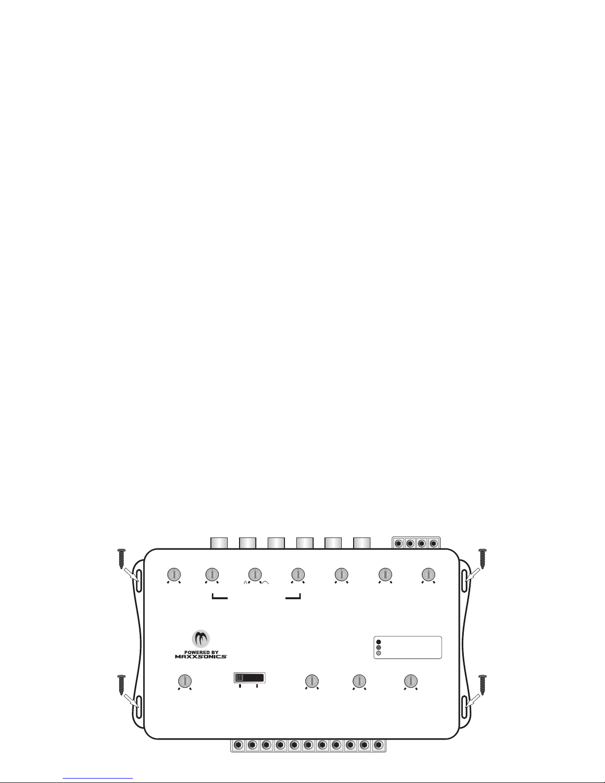
HIGH LEVEL FRONT(F) & REAR(R) INPUT CONTROL:
Variable from 40Volts to 4Volts. This control is used to match the output signal level from your headunit to your
Front and Rear speakers.
SUBWOOFER INPUT MODE SELECTOR:
This switch allows for your to select 4 CH MONO to sum the input signal from the Front and Rear channels
when a factory subwoofer is not present for signal or HIGH LEVELwhen a factory subwoofer output is available
for signal.
FRONT HIGH PASS FILTER:
Variable from 15Hz to 200Hz. This filter features a 12dB per Octave roll off.This means that the FRONT HIGH
PASS FILTER has a gradual roll-off and allows for smooth cutoff. The FRONT HIGH PASS FILTER allows
frequencies above your selected setting to pass thru while cutting out frequencies below your selected setting
for the front speakers.
REAR HIGH PASS FILTER:
Variable from 15Hz to 200Hz. This filter features a 12dB per Octave roll off.This means that the REAR HIGH
PASS FILTER has a gradual roll-off and allows for smooth cutoff. The REAR HIGH PASS FILTER allows
frequencies above your selected setting to pass thru while cutting out frequencies below your selected setting
for the rear speakers.
FRONT & REAR STEREO OUTPUT LEVEL:
Variable from 4Volts to 9Volts. This control is used to adjust signal output voltage to your amplifier. Use caution
when adjusting the signal output to be provided to your amplifier as you can damage your amplifier if you
provide more signal than your amplifier is rated to handle.
CLIPPING CONTROL: While adjusting the headunit, MX-1, or amplifiers, the CLIPPING CONTROLLED may
illuminate in one of the following colors to alert you of an existing condition. These indicators give the user a
chance to identify incorrect settings or high distortion before it is damaging to the equipment allowing them to
correct the volume or settings.
- GREEN: Indicates a Pre-Clip condition, which is safe and normal operation.
- YELLOW: Indicates a Soft-Clip condition, which is safe and normal operation, but you are close to a hard clip.
- RED: Indicates a Hard-Clip condition which is potentially damaging to the MX-1, amplifiers, speakers and
subwoofers in the system. Evaluate and adjust crossovers and Levels so that this condition is not present.
4