PAGE 9Help: 888-426-5001 QualityWaterForLess.com
4 ›PlumBInG youR autotRol 268/760 ValVe
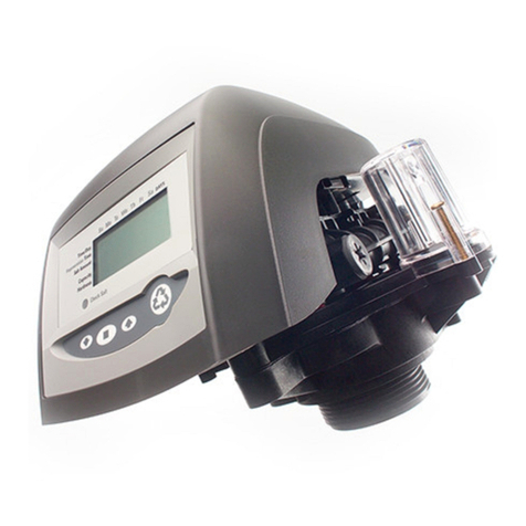
1) Before beginning your installation, please first
familiarize yourself with the IN and OUT ports on
the Autotrol 268/760 Valve.
In order to prevent
damage to your home and to the softener
system, install the softener according to the IN
and OUT arrows on the softener valve
2) Locate the main shut-off valve for your house
and turn it to the OFF position. If you have a
private well, this valve should be near your well
pressure tank. If you have a city water supply,
your valve should be near your water meter
3) Depressurize and drain your home of water by
turning on all faucets and fixtures in your home,
including those outside
4) Pick your installation point and cut a section
of pipe out to run to and from your softener.
In most cases it is preferred to keep outside
lines UNSOFTENED. If you wish to keep your
outside lines unsoftened, you must plumb
BYPASS lines to run hard water to these fix-
tures
5) Using soldered copper, PVC plastic pipe, or flex-
ible connections, plumb the system according to
all local plumbing codes.
If using copper pipe,
please pre-fabricate at least a 12” section
of pipe for the IN and OUT bound lines and
use a wet rag on the lines being soldered to
prevent heat damage during soldering
6) Once all connections have been made, place the
system into bypass by either using your existing
3-valve bypass (if ordered with a YOKE adap-
tor), or by switching your included bypass ON (if
ordered with a bypass)
7) Next, gradually open your main valve and allow
all air in your plumbing lines to escape slowly.
Also, you may turn off all outside and inside
faucets and fixtures
8) Check for leaks at your plumbing site for signs
of slow drips and rectify if necessary.
Please do
NOT take the softener out of BYPASS as the
installation is not completed yet. Please take
this opportunity to check and re-check the IN
and OUT ports to make sure they are correct
5 ›makInG tHe BRIne tank ConneCtIon
1) Locate the brine port on the right side of the
control valve and apply Teflon tape in a clock-
wise fashion to the threading. Then attach the L
shape fitting to the port (Figure 9-A).
Please use
care not to overtighten
2) Locate the included section of Brine Tubing and
assemble the brine fitting to the brine tubing.
Finger-tighten the nut and then use a wrench to
turn the fitting ½ turn more until snug as shown
in Figure 9-B.
Please use care not to over-
tighten
FIGuRe 9-a FIGuRe 9-B


