Avantes 785nm User manual

01-04-16 AvaRaman Bundle Manual 1
Operation Manual
785nm Integrated Raman Probe

01-04-16 AvaRaman Bundle Manual 1
Table of Contents
Product Summary.............................................................................. 2
Explanation of Symbols Used In This Manual & On Module .............................. 2
Laser Safety .................................................................................... 3
I. Included Components .................................................................. 4
II. Laser Start-Up (controlling output power via front panel)........................ 4
IIa. Laser Start-Up (External Power Control Mode) ..................................... 9
III. Laser Shut Down......................................................................... 9
IV. System Specifications .................................................................10
V. Warranty ................................................................................12
VI. Technical Support Contact Information ............................................14
!
Read Manual
Before Use

01-04-16 AvaRaman Bundle Manual 2
Product Summary
The 785nm Integrated Raman Probe includes an integrated wavelength stabilized laser source with Raman
filter packs, beam shaping optics and high efficiency Raman spectra collection optics.
The laser unit is a Class 3B laser product with laser emission at 785 nm and output power levels exceeding
350 mW. Extreme care should be taken when operating this unit to avoid potentially hazardous exposure to
both eyes and skin. Users should wear eye protection when operating this unit and should avoid exposure to
the output beam.
Explanation of Symbols Used In This Manual & On Module
The following table details the symbols placed on the module and in this manual, and their meanings:
Symbol
Description
Identifies important information that should be read and thoroughly
understood before operating the equipment.
Laser Warning Label
Explanatory label –Documents important information about
equipment specifications and features.
General Information Label –Provides information that may be helpful
and documents IEC 60825-1 & FDA Compliance information
O
Symbol indicating “Off” position on a switch
I
Symbol indicating “On” position on a switch
Protective Ground Symbol

01-04-16 AvaRaman Bundle Manual 3
Laser Safety
Caution –use of controls or adjustments or performance of procedures other than those specified
herein may result in hazardous radiation exposure.
Do not point laser or allow laser light to be directed or reflected toward other people or reflective
objects.
Do not modify unit or remove protective covers or housings
Laser light emitted from this equipment may be sufficient to ignite some materials and initiate fire
Never operate laser if unit is defective or if safety covers, interlocks, and labels are damaged or
missing.
This Laser Product is designated as Class 3B during all procedures of operation, maintenance and service.
Non Accessible Internal Laser Parameters:
Wavelength
785 nm
Laser Power for Classification
>350 mW
Beam Diameter
Focused Beam
Divergence
~12 degrees (after focus)
TE Mode / Beam profile
Multi-spatial mode
Mode of Operation
CW or Quasi CW if external modulation is applied
The use of laser safety goggles is required when operating this product.
Laser Safety Eyewear specifications:
Optical density: ND5 or higher at 785 nm
ND 1 or lower at 600 nm
Top and side shield protection
CE certified
Failure to wear appropriate eye protection may result in permanent eye damage
Suggested sources and model #’s:
oThorLabs, Model #: LG9
oNoIR Lasershield, Model #: DI2, Model #: CYN or Model #: YAD
Additional helpful information may be found in ANSI Z136.1 “Standard For Safe Use of Lasers”. This
document can be obtained at www.rli.com or www.laserinstitute.org
INVISIBLE LASER RADIATION
Avoid Eye or Skin Exposure to Direct
or Scattered Radiation

01-04-16 AvaRaman Bundle Manual 4
I. Included Components
The 785nm Integrated Raman Probe comes complete with an internal 350 mW spectrum stabilized laser
module that contains an integral Thermo-Electric Cooler (TEC) and thermistor for monitoring the internal
temperature of the laser platform. The unit comes complete with a laser enable switch for safety, an LED
readout, an output power control dial, a safety key lockout, a remote interlock, and an emergency shut-off
switch, Raman filter packs, beam shaping optics and high efficiency Raman spectra collection optics and a
custom fiber optic cable with a FC/PC termination. Additionally the 785nm Integrated Raman Probe comes
complete with a UL/CE, and IEC compliant control box providing a variety of power control options including
TTL, analog, and USB.
II. Laser Start-Up (controlling output power via front panel)
The following steps and illustrations should be followed when starting the 785nm Integrated Raman Probe.
Caution—use of controls or adjustments, or performance of procedures other than those specified herein
may result in hazardous radiation exposure.
1. Connect the DC power supply provided with the unit to the back of the control box.
Insert DC power
plug into socket.

01-04-16 AvaRaman Bundle Manual 5
2. Plug in the DC power supply into a standard 100 V –240 V AC electrical outlet making sure that the
Master Power key is set to the off (Vertical) position.
3. Connect the DB9 I/O cable of the probe into the front panel on the control box and secure with the
thumbscrews.
Insert Key in
Vertical “Off”
position
Insert DB9
I/O cable

01-04-16 AvaRaman Bundle Manual 6
4. Insert the fiber optic cable from the probe into the FC/PC port of your spectrometer. Do not fully
tighten the connector because you will need to rotate the fiber later.
5. If measuring solid samples attach the distance regulator to the tip of the probe shaft. This will
reduce the working distance to ~0.5mm, allowing contact measurements.
Insert fiber optic
cable into SMA 905
bulkhead on your
spectrometer
Attach
Distance
Regulator for
Solid Samples
Insert fiber optic
cable into FC/PC
bulkhead on your
spectrometer

01-04-16 AvaRaman Bundle Manual 7
6. Open the laser shutter.
7. Place solid sample in contact with the distance regulator, or if using a liquid sample position the
sample in front of the probe and adjust the position so that the liquid is ~9mm from the end of the
probe shaft (without distance regulator).
Point Probe
at Sample
Open Laser
Shutter

01-04-16 AvaRaman Bundle Manual 8
8. Turn the key to the in the back of the unit to the on position, turn the dial on the front of the control
box to the desired laser power (Note: the readout on the unit is in current, not power) and press the
laser enable button to turn on the laser inside of the probe.
Note that this laser is configured with a remote interlock. IPS has provided an RJ-11 (4-pin telephone jack)
that is pre-wired to provide a closed loop connection for the interlock. Removal of the RJ-11 connector or
break in the closed loop circuit provided will result in a laser interrupt and the system will be reset to
standby mode. Users may reconfigure the RJ-11 connector to provide a closed loop that interactively couples
with their system or facility by replacing the short length of wire with longer closed loop connections if
desired.
RJ-11
Interlock
Enable Laser
and collect
Spectra

01-04-16 AvaRaman Bundle Manual 9
IIa. Laser Start-Up (External Power Control Mode)
Note: The laser unit is normally designed for operation by interacting with front panel controls, however
users may wish to modulate or adjust the output power of the laser module in some circumstances. The unit
is equipped with an external DC bias port located on the back panel of the module. The following steps
should be taken if the user wishes to control the laser output power remotely via a signal generator or
computer:
Caution—use of controls or adjustments, or performance of procedures other than those specified herein
may result in hazardous radiation exposure.
1. Ensure that the laser is not operating by pressing the laser ON switch and assuring that the laser on
LED is not illuminated.
2. Switch the mode selection switch located on the back panel to the “External” position (the Amber
operating mode LED labeled “External” will be illuminated).
3. Connect a BNC cable to the port labeled “Control” on the back panel. The user may apply a DC bias
between 0 and 1.0 V to modulate the laser or to adjust the laser’s output power. 0 V corresponds to
0 power, 1.0 V corresponds to full power. The unit can be modulated at rates up to approximately 1
KHz.
4. Turn on the laser by momentarily depressing the Laser On switch on the front panel. The laser will
now output a variable amount of output power that is dependent upon the DC bias voltage that has
been applied to the Control port on the back panel.
5. The unit can also be controlled via USB using our LCU software with a graphical computer interface
allowing the laser to be turned on and off. It also allows a percentage of the power to be set from 10
to 100%.The power is set by pulse width modulation (PWM) at around 1000 Hz.
III. Laser Shut Down
The following steps should be followed when shutting down the Laser Module.
1. Depress the Laser On button on the front panel and assure that the Laser On LED is not illuminated.
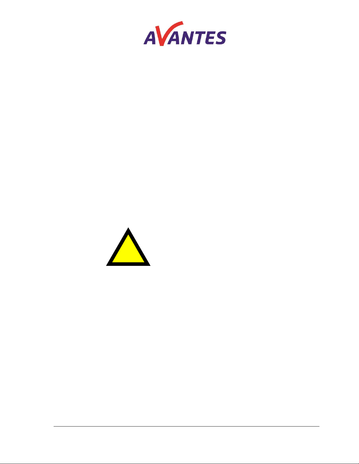
2. Turn the master power key switch on the back panel counter clockwise from the horizontal “On”
position to the vertical “Off” position.
3. Disconnect fiber patch cord and power cables as needed.

01-04-16 AvaRaman Bundle Manual 10
IV. System Specifications
General Specifications
Excitation
Integral 785nm wavelength stabilized laser with <0.15nm FWHM bandwidth
Collection
1.5m long, proprietary high throughput fiber with FC/PC male connector
Cut-on
200cm-1 cut-on
Electronic Connection
DB9 cable with safety interlock
Power Control
Manual power adjustment knob, Analog / TLL modulation via BNC connector, or MicroUSB
Power Supply
3 A, 5VDC
Shaft
1.6inch (40.5 mm) length by 0.25inch (6.35mm) diameter 316L Stainless Steal
Working Distance
9mm from shaft, or 0.5mm from distance regulator.
Operating Temperature
100C to 400C
Storage Temperature
-20oC to 80oC
Humidity
0 - 80% non-condensing
Parameter Unit Min Typ Max Notes
Laser Optical output power mW 350 450 495
Output power stability % ± 1
Peak wavelength nm 784.5 785 785.5
3 dB bandwidth (FWHM) nm 0.1 0.15
Operating Temperature Range (Case) Deg C 10 40
Case Temperature
Power Consumption W3 7
Case temp between 10 and 40 deg C
Seconds 180
Cold Start - to < 1 wavenumber
1
Warm Start - to < 1 wavenumber
3
Warm Start - to < 0.1 wavenumber
Absolute Maximum Ratings
Laser Module Operational Current A 1 3
Laser Module Operational Voltage V 4.9 5 5.1
Compliance
Wavelength Stability

01-04-16 AvaRaman Bundle Manual 12
V. Warranty
The unit is warranted against defects in materials and workmanship for a period of one year from date of
shipment. During the warranty period, Avantes will, at its option, either repair or replace products which
prove to be defective.
The unit does not contain any user serviceable components and does not require any preventative
maintenance operations during the device lifetime. Opening, modification and or servicing of this unit is
expressly prohibited and will result in nullification of product warranty. All necessary service and repair will
be made at the Avantes facility upon request of a Return Material Authorization (RMA) request and return of
the unit.
This warranty is in lieu of all other guarantees expressed or implied and does not cover incidental or
consequential loss or improper operation/handling by operator.
Laser Safety and Compliance Labels:
1. Laser warning and Aperture label:
-Identifies location of output beam
Is located on the front panel of the module, immediately adjacent to the FC/PC bulkhead connector.
2. Class 3B laser explanatory label: The label detailing:
-Laser exposure warnings
-Laser wavelength and maximum output power levels
-Laser classification
is located on the top of the module in the front left hand corner.

01-04-16 AvaRaman Bundle Manual 13
3. Manufacturers ID label : The label detailing:
-Manufacturer’s address & the date of manufacture of item
is located on the left hand panel of the module
4. Certification statement label: The label detailing:
-Compliance with FDA performance standards is located on the top center of the rear panel.
5. Labeling indicating compliance with FDA performance standards can be found on the top section of
the rear panel on the laser module above the master power key switch.
6. Labeling indicating model #, and Serial # of the unit is located on the back panel above the BNC
modulation input port connector.
Laser
Explanatory
Label
Laser Aperture
Label

01-04-16 AvaRaman Bundle Manual 14
7. Labeling indicating date and location of manufacture can be found on the removable side panel (left
hand side of the module when front panel faces forward)
VI. Technical Support Contact Information
Questions regarding the use or operation of this product may be directed to:
Avantes BV
Email: support@avantes.com
Phone: +31 313 670 170
Laser
Complianc
e Label
Compliance
Statement
Date and
Location of
Manufacture
Module Model #
and S/N
This manual suits for next models
1
Table of contents
Other Avantes Measuring Instrument manuals
Popular Measuring Instrument manuals by other brands

sebaKMT
sebaKMT Easyflex Com instruction manual

EXFO
EXFO FTB-1v2 Pro Quick reference guide

YOKOGAWA
YOKOGAWA ROTAMASS Total Insight General instruction manual

LaserLiner
LaserLiner AirflowTest-Master manual

LSI LASTEM
LSI LASTEM Heat Shield Quick user guide

PCB Piezotronics
PCB Piezotronics 357E90 Installation and operating manual

Elgo
Elgo EMAX Series operating manual

TSO Products
TSO Products MTR-X SET user guide

Endress+Hauser
Endress+Hauser Analytik Jena multi N/C 2100S operating manual

Badger Meter
Badger Meter IOG Series Installation and operation manual

Kapro
Kapro 883N user manual

Siemens
Siemens Opdima MAMMOMAT 1000 Installation and start-up instructions