Avdel HP21 User manual

HydraPac Hydraulic Power Unit
HP21, HP41, HP51
I n s t r u c t i o n M a n u a l


3
Contents
Warranty
The ninety day warranty herein expressed shall be the exclusive warranty on items
manufactured by seller and shall be in the place and stead of any other warranty, expressed or
implied, including but not limited to the implied warranties of merchantability and fitness for a
particular purpose.
Seller shall not be liable for any loss or damage resulting from delays or non-fulfilment or
orders owing to strikes, fires, accidents, transportation companies or for any reason or
reasons beyond the control of seller or its suppliers.
All warranty claims must be submitted to the seller in writing, within 90 days from date of
shipment, and no returns will be accepted without written permission.
Other provisions hereof notwithstanding, seller shall not be liable for any loss of business
profits or any incidental or consequential damages incurred by Buyer or any third person in
connection with the items or use thereof, however caused.
Unit Warranty
Seller expressly disclaims any warranty express or implied, as to the condition, design,
operation, merchantability or fitness for use of any unit, or part(s) thereof not manufactured
and/or supplied by seller. The only warranties made with respect to such unit or part(s)
thereof are those made by the manufacturer thereof and seller agrees to cooperate with buyer
in enforcing such warranties when such action is necessary. Seller agrees to repair or replace
F.O.B. seller's plant, any unit or part(s) thereof manufactured by it and proved to seller to be
defective due to faulty workmanship or material.
Servicing the Tool
Daily / Weekly 21
Every 1200 Working Hours (at least once a year) 21
Service Tools 21
Hydraulic Oil General Safety Data 21
Fault Diagnosis
Symptom, Possible Cause & Remedy 22
Safety Rules 4
Specifications
Intent of Use 5
Tool Specification 5
Tool Dimensions 5
Putting into Service
Principle of Operation 6
Preparation for Use 6
Operating Instructions 6
Mechanical Maintenance
Dismantling Instructions 7
Assembly 8-9
General Assembly and Parts List for HP21 10-11
General Assembly and Parts List for HP41 12-13
General Assembly and Parts List for HP51 14-15
General Assembly and Parts List for
Combination Valve 16
Electrical Maintenance
Minor Maintenance 17
Major Maintenance 17
Assembly 17
Wiring Diagram for HP21 18
Wiring Diagram for HP41 19
Wiring Diagram for HP51 20
Avdel UK Limited policy is one of continuous product development and improvement and we reserve the right to change the specification of any product without prior notice.

4
Safety
1Do not use outside the design intent.
2Do not use equipment with this HydraPac other than that recommended and supplied by Avdel UK Limited.
3Any modification undertaken by the customer to the HydraPac shall be the customer’s entire responsibility.
4Always disconnect the HydraPac from the power supply before attempting any work.
5The HydraPac should always be positioned on a flat stable surface.
6It is recommended that the HydraPac only be started with hoses and an installation tool attached.
7Do not fit flexible hoses rated at less than 10 000 psi (69 mPa).
8The operating pressure shall not exceed 8000 psi (55.2 mPa).
9Take care to avoid entanglement of the trailing cable with any object on the floor.
10 The HydraPac should be kept clean for safe and easy operation.
11 When moving the HydraPac from place to place only pull on the handle, not on the hoses.
12 Ear protection must be worn by the operator and others in the vicinity utilising lockbolt installation tooling as noise levels for these tools
exceed the permitted maximum. For these values see the installation tool technical manuals.
This instruction manual must be read with particular attention to the following safety rules, by any person
installing, operating, or servicing this tool.
CAUTIONS
AVDEL RECOMMENDS THAT ONLY HYDRADRIV TOOLING BE USED WITH THE HYDRAPACS AS OTHER MAKES OF HYDRAULIC
TOOLING MAY NOT OPERATE AT THE SAFE DESIGNED WORKING PRESSURES.
KEEP DIRT AND FOREIGN MATTER OUT OF THE HYDRAULIC SYSTEMS AS THIS WILL CAUSE THE HYDRAPAC TO
MALFUNCTION.

5
To convert electrical energy into hydraulic energy that in turn will drive various hand held Hydraulic Powered Tools. The design pressures of
these Tools must be compatible with the working pressures stipulated in the Tool Specifications below.
HYDRAPAC
H
L W
Model HP21 HP41 HP51
Electric Motor 2.2 kW 4 pole flange mount
Power Supply 220/230V 380/415V 525V
1PH 3PH 3PH
50 Hz 50 Hz 50Hz
Full Load Amps 15.00 5.3 3.8
Working Pressure
Pull 55.2 mPa (8000 psi)
Return 20.7 ma (3000 psi)
Delivery Volumes 2.6 l/min 3.3 l/min 3.3 l/min
Hydraulic Fluid ISO VG 46 OR EQUIVALENT
Pump 4 Cylinder radial
Control 24V dc solenoid controlled directional valve coupled to
a hydrafast combination pressure control and relief valve
Length (L) 815 mm (32")
Height (H) 530 mm (21")
Width (W) 360 mm (14")
Mass 98 kg with full oil tank
Avdel UK Limited policy is one of continuous product development and improvement and we reserve the right to change the specification of any product without prior notice.
Inten t o f Us e
Tool Specification
Tool Dimensions
Specifications

6
Putting into Service
The HydraPac is a High Pressure Hydraulic Pump delivering two different operating pressures for the two cycles of the tooling
operation. A high pressure for the installation cycle (or pull cycle) and a lower pressure for the ejection cycle (or return cycle). Each
HydraPac is provided with 10 m of trailing cable for connection of the electric power supply, a pair of Hydraulic Quick Couplers and an
electrical socket for the Control Cord Connection.
When connected to the correct power supply and then coupled hydraulically and electrically to an Installation Tool, the HydraPac will
start up on depressing the Trigger Switch on the Installation Tool. With the switch remaining depressed, the solenoid valve in the
HydraPac then becomes energised directing the Oil to the High Pressure Installation side of the Installation Tool.
Note: 1. If the Trigger Switch is not released before the piston in the Installation Tool reaches the end of its stroke, the
Combination Valve will enter the idle mode thereby safely dumping all the Hydraulic Pressure into the tank. This
"Dumping" will also occur if any blockage occurs in the Hydraulic System.
2. In the unlikely event of a total failure of the Primary Safety Hydraulic Pressure Relief Valve Mechanism, a second Safety
Relief Valve is located on the Pump Manifold.
On completion of the LockBolt installation cycle, the trigger switch is released, de-energising the Solenoid Valve which directs the
lower pressure oil flow to the return side of the Installation Tool. On completion of the return cycle the Combination Valve automatically
puts the HydraPac into "Idle Mode". The oil continues to flow through the Valve Assembly but returns directly to the tank at the idle
pressure of 1.3 mPa. On depressing the Tool Trigger Switch, the cycle is initiated.
If the Tool Trigger switch in not depressed within a preset period (normally set at 10 seconds for T10 Tools, 15 seconds for T30
Tools, and 25 seconds forT51 Tools), the HydraPac will enter its "Sleep Mode" thereby conserving electricity and wear and tear on the
components.
The period before entering the "Sleep Mode" can be varied to suit the users needs and conditions.
The HydraPac will automatically start up again on depressing the Tool Trigger switch again.
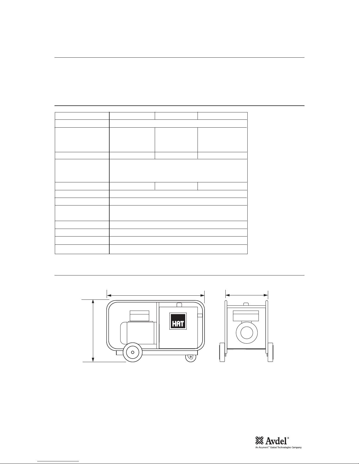
•Check the Oil Level in the Tank using the Gauge located at the front of the HydraPac. Fill and/or top-up as required.
Note: Export units are shipped dry.
•Ensure that the Isolator on the HydraPac Electric Enclosure is turned to "Off''.
•Connect the Power Supply Trailing Cable to the correct power supply for the Hydrapac Model (see page 5) and turn the power
supply switch "On".
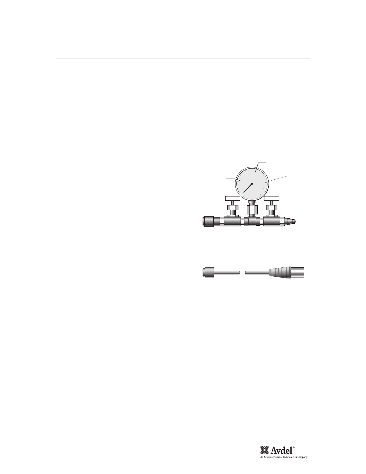
•Connect one end of the Hose Set Quick Couplers to the HydraPac and the other end to each other.
•Connect the Hose Set Control Cord to the Socket in the Electrical Enclosure on the HydraPac and to the Installation Tool to be
used.
•Turn the HydraPac Isolator to "On".
•Depress and release the Installation Tool Trigger Switch. The HydraPac should now be running in the "Idle Mode".
•Allow the HydraPac to go into its "Sleep Mode". Repeat this step and the previous step a few times. This will allow the oil to
circulate freely through the hoses and back to the tank removing any possible air from the system.
•With the HydraPac in the "Sleep Mode", connect the Installation Tool to be used to the Hose Set.
•Cycle the Tool a few times checking if the "Sleep Mode" timer allows enough time for the tool to complete its "return cycle".
Note: The timer setting can be increased or decreased to suit individual tools and application conditions.
The HAT System is now ready for use.
For Operating Instructions please refer to the Instructions contained in the Installation Tool Manual.
IMPORTANT
Read the safety rules on page 4 carefully
Pr i nc i pl e o f Op e ra t io n
Pr ep a ra t io n f or U s e
Op e ra t in g I ns t ru c ti o ns

7
Mechanical Maintenance
Preparation
•Disconnect and remove the hose set and its control cord from the HydraPac.
•Remove the Tank Cover using a 5 mm allen key.
•Remove the Drain Plug with a 13mm spanner and drain the oil.
•Disconnect the electrical connection from the solenoid on the Valve Set using a 4mm flat screwdriver.
•Remove the steel hydraulic pipe connecting the pump to the Valve Set using a 20 mm spanner.
Removing the Valve Set (C025 and C027)
•Note the relative positions of the Male and Female couplers. Unscrew and remove the Hydraulic Quick Couplers 2using a 24mm
spanner.
•Unscrew the Bulkhead Adaptors 1and remove the Valve Set comprising Directional Valve 101B and the Combination Valve 114
using a 27 and a 24 mm spanner.
Separating the Valve Set
•Unscrew and remove the four M5 socket screws located in the Directional Valve 101B using a 4 mm allen key
To Strip the Combination Valve
•Unscrew the four M4 Socket Head Cap Screws 103 securing each of the two Spring Domes 106 using a 3 mm allen key.
•Remove the two Spring Domes and take out the Springs 108 and Bearing Pads 107.
•Remove the two Plungers 109 from the Combination Valve Body 110 taking care to identify each ones own location.
Directional Valve
The only component on this unit that can be replaced is the Solenoid Coil. This can be removed by unscrewing the nylon securing nut
and sliding off the Coil. Care should be taken not to lose the square section rubber cushion between the Nut and the Coil and the 'O'
Ring behind the Coil.
Assembly of the coil is simply the reverse to the stripping procedure above.
Removing the Pump
•Remove the eight M10 Nyloc Nuts 36 using a 17 mm spanner
•Slide the Manifold Flange 7off the Studs 15.
•Slide the four Pump Elements 8off the Studs 15 taking care to keep them intact once free of the Bearing 14 by supporting the
Piston with a finger.
Removing the Electric Motor
•Push the connecting block for the solenoid out of the Hirschmann Cap and disconnect the two wires using a 4 mm flat
screwdriver.
•Unscrew and remove the Gland Clamp Screw using a 17 mm spanner and feed the wire through the Gland 18.
•Support the Electric Motor 16 and remove the two M6 Socket Head Cap Screws located inside the Tank using a 5 mm allen key.
•Slide the motor away from the tank.
•The Eccentric Shaft Bearing 14 can be removed with a conventional bearing puller.
Note: Only remove this item if it has to be replaced or the motor stripped for extensive maintenance.
WARNINGS
Before commencing with any maintenance whatsoever, the Isolator on the HydraPac Control Box must be turned
"OFF" and the Power Supply Trailing Cable be disconnected from the power supply.
Due to the high hydraulic operating pressures, it is imperative that only suitably qualified, trained and equipped
personnel be permitted to service or repair these units.
Item numbers in bold refer to the general assembly and combination valve drawings and parts lists on pages 10-16.
Di s ma n tl i ng t h e No s e As s em b ly

8
As s em b ly
Mechanical Maintenance
Fitting the Eccentric Bearing
•Remove the Fan Motor Cover by unscrewing the 4 screws using a 6 mm wide screwdriver.
•Place this end of the Shaft against a solid base.
•Fit the Eccentric Shaft Bearing 14 onto the Shaft.
Note: It is strongly recommended that a small press be utilised for this procedure.
•Replace the Fan Cover and 4 screws using a 4 mm screwdriver.
Installing the Electric Motor
•Ensure that both the Motor Flange, the Gasket and the Mounting Plate 17 are free from any dirt.
•Smear both sides of the Gasket with a non-adhesive sealant.
•Supporting the Motor 16 and ensuring that the Electric Enclosure 32 is on top, slide the motor studs through the holes in the
Mounting Plate.
•Secure the Motor to the Plate from inside the Tank with the two M6 Socket Head Cap Screws using a 5 mm allen key
•Feed the Solenoid Wire through the Gland 29 in the Mounting Plate leaving a little slack between the Electric Enclosure Assembly
32 and the Mounting Plate 17 and tighten the Gland Screw using a 17mm spanner.
Installing the Pump
•Ensure that the 'O' rings are firmly in position on each Element's Discharge Port.
•With the Discharge Port facing away from the Mounting Plate 17, lift the Piston against the Spring and slide the Element 8over
the Studs 15 and the Bearing 14 until they are up against the Mounting Plate. Repeat for all four Elements.
Note: HP41 and HP51 models have four equal size Elements. The HP21 and HP42 however have two different size elements.
Equal size Elements MUST be assembled so that they are diametrically opposed.
•Slide the Manifold Flange 7over the Studs 15 ensuring that the ports are facing the Elements and that the symbol 'T' is located
on top.
•Tighten the eight Nyloc Nuts 36 to 30 Nm in an opposing sequence using a 17 mm socket and torque wrench.
Assembling the Combination Valve
•Replace the two Plungers 109 in their respective ports.
Note: It is essential for efficient Valve Functioning that the Plungers be placed in their original positions.
•Loosen the two nuts with a 10mm spanner and a 5 mm allen key and back-off the Pressure Adjusting Screws on top of the Spring
Domes 106 about three turns.
•Insert the Bearing Pads 107 and Springs 108 in that order into the Spring Domes 106.
•Locate the Spring Dome Spigots in the matching recesses in the Valve Body 110 and secure with the four Screws 103 in each
Dome using a 3 mm allen key.
Assembling the Valve Set
•Ensure that the four 'O' Ring Seals 113 are in place on top of the face of the Directional Valve 101.
•Place the Directional Valve 101 over the Combination Valve 114, locating the Dowel Pin in the recess provided.
•Secure the two Valves with the four M5 Socket Head Cap Screws 102 using a 4 mm allen key.
Installing the Valve Set
•Screw the two Nuts on the Bulkhead Adaptors 1as far on as possible by hand and slide the Washers as close as possible to
them.
•Ensuring that the two 'O' Rings 111 are in place over Discharge Ports in the Combination Valve 114, place the Valve over the two
holes provided in the tank.
•Screw the long side of the Bulkhead Adaptors 1into the ports and tighten using a 24 mm spanner
•Secure the valve set to the tank by tightening the two Nuts up against the Washers with a 27 mm spanner.
•Looking from the non-motor end of the HydraPac, fit the Male Quick Coupler 2A to the Right Hand Side Adaptor and the Female
Quick Coupler 2B to the Left Hand Side and tighten using a 24 mm spanner for both.
Item numbers in bold refer to the general assembly and combination valve drawings and parts lists on pages 10-16.

9
As s em b ly ( c on t in u ed )
Mechanical Maintenance
Final Assembly
•Connect the Steel Pipe to the Pump and Valve Set and tighten using a 20 mm spanner.
•Connect the solenoid wire to its terminal block using a 3 mm flat screwdriver. Place the block in position on the solenoid and
secure with the screws provided.
•Ensure that the Oil Drain Plug has been replaced and tightened using a 13 mm spanner.
•Fill to the maximum level indicated on the Oil Level Indicator 5with the grade of hydraulic oil stipulated in the Technical
Specifications on page 5.
Pressure Setting
•Connect the Pressure Setting Gauge Set and Hoses to the HydraPac.
•Plug in the Setting Trigger (see illustration below).
•Place the Tank Cover Assembly loosely in position. This is to prevent
excessive oil splash during setting.
•Connect to the HydraPac Power Supply and switch on.
•Turn the isolator on the electric enclosure to 'On' .
•Ensure that both Valves on the Pressure Setting Gauge Set are fully
open.
•Depress and release the Trigger a few times allowing the oil to circulate
freely. This will remove all the air from the hydraulic system and also
indicate if the Directional Valve is functioning.
•Keeping the Trigger Switch depressed, slowly close the Valve 'A'.
reading the pressure on the gauge take note of the pressure when the
release valve opens. Adjust the screw on the left hand side Spring
Dome, (the lower of the two domes) to obtain the setting given on the
Gauge Set illustration. Once the correct pressure setting has been
achieved, lock the adjusting screw in place with the nut provided using a
10 mm spanner.
•To set the Return Pressure repeat as in previous step but with the
Trigger Switch released. Valve 'A' must be fully open and Valve 'B'
utilised to obtain the setting. Adjustments for the pressure are to be made on the second Spring Dome.
•On completion of the pressure settings, replace and secure the tank cover with the 10 mm socket head cap screw using a 5 mm
allen Key and reset the timer if need be.
Note: It may be necessary during Pressure Setting to temporarily increase the delay time on the "Sleep Mode" Timer.
Item numbers in bold refer to the general assembly and combination valve drawings and parts lists on pages 10-16.
ALSO REQUIRES TWO HOSES 1.5 m LONG \COMPLETE
WITH THE RELATIVE QUICK COUPLERS EACH END
0
21.5
20.0
56.2
56.9
100
mPa
RETURN
PRESSURE
FEMALE
QUICK
COUPLER
TEENEEDLE
VALVE
'A'
PULL
PRESSURE
DRY GAUGE
PART No. C157
GLYCERINE FILLED GAUGE
PART No. C 158
NEEDLE
VALVE
MALE
QUICK
COUPLER
'B'
+- 2 m 2 CORE 0.5 mm2CABTYRE
TRIGGER
SWITCH
MALE
PLUG
Pressure Setting Gauge Set
Arrangement of Setting Trigger

10
General Assembly of HP21 HydraPac
3
5
4
6
35*
7
10
12
ENCLOSURE ASSEMBLY
32
GLAND
C109
18
29
28
27
26
25
24
23
22
16
19
17
9
SCREW
4 OFF
2A/B
1
FRAME COMPLETE
(CHASSIS, OIL TANK
LID AND GASKET,
OUTER FRAME
AND HANDLE)
35*
33
TO ENCLOSURE
15
14
21
20
13
TO
SOLENOID
11
8A
8B
8A
8B
31
34
FUSE HOLDER
(NOT SHOWN)
30

11
Par ts List for HP21 HydraPac
ITEM PART Nº DESCRIPTION QTY
HYDRAPAC HP21 VALVE PARTS LIST
ITEM PART Nº DESCRIPTION QTY
1 CO28 BULK HEAD ADAPTOR 2
2A/B HS01 HYDRAULIC QUICK COUPLER (MALE/FEMALE) 2
3 C166 DIRECTIONAL VALVE 1
4 CO27 COMBINATION VALVE 1
5 C116 OIL LEVEL INDICATOR 1
6 CO86 ELBOW 2
7 CO36 MANIFOLD FLANGE 1
8A PE8 PUMP ELEMENTS 2
8B PE10 PUMP ELEMENTS 2
9 C231 RELIEF VALVE 1
10 C117 OIL FILLER BREATHER 1
11 CO95 SURGE ARRESTOR 1
12 CO30 ISOLATOR 1
13 C081 TRANSFORMER 220V 1
14 CO35 ECCENTRIC SHAFT BEARING 1
15 CO34 STUD 8
16 CO22 MOTOR 1
17 CO89 MOUNTING PLATE 1
18 C104 GLAND 1
19 CO93 TRAILING CABLE 1
20 CO51 THERMAL OVERLOAD 1
21 CO50 CONTACTOR 1
22 CO30 ISOLATOR 1
23 CO80 BASE (RELAY) 1
24 CO79 RELAY 1
25 C124 BASE (TIMER) 1
26 C132 TIMER 1
27 C097 BRIDGE RECTIFIER 1
28 C111 CANNON FLUSH PLUG 1
29 C109 GLAND 1
30 C107 FUSE HOLDER (NOT SHOWN) 1
31 C105 ENCLOSURE LID 1
32 C090 ENCLOSURE ASSEMBLY 1
33 C119 WHEEL 2
34 CO77 CASTOR WHEEL 1
35 CO20
FRAME COMPLETE (CHASSIS, OIL TANK, LID & GASKET, OUTER FRAME & HANDLE)
1

12
General Assembly of HP41 HydraPac
3
5
4
6
35*
7
10
12
ENCLOSURE ASSEMBLY
32
GLAND
C109
18
29
28
27
26
25
24
23
22
16
19
17
9
SCREW
4 OFF
2A/B
1
FRAME COMPLETE
(CHASSIS, OIL TANK
LID AND GASKET,
OUTER FRAME
AND HANDLE)
35*
33
TO ENCLOSURE
15
14
21
20
13
TO
SOLENOID
11A
11B
8
8
31
34
FUSE HOLDER
(NOT SHOWN)
30

13
Par ts List for HP41 HydraPac
ITEM PART Nº DESCRIPTION QTY
HYDRAPAC HP41 VALVE PARTS LIST
ITEM PART Nº DESCRIPTION QTY
1 CO28 BULK HEAD ADAPTOR 2
2A/B HS01 HYDRAULIC QUICK COUPLER (MALE/FEMALE) 2
3 C166 DIRECTIONAL VALVE 1
4 CO27 COMBINATION VALVE 1
5 C116 OIL LEVEL INDICATOR 1
6 CO86 ELBOW 2
7 CO36 MANIFOLD FLANGE 1
8 PE10 PUMP ELEMENTS 4
9 C231 RELIEF VALVE 1
10 C117 OIL FILLER BREATHER 1
11A CO95 SURGE ARRESTOR 1
11B CO96 SURGE ARRESTOR 1
12 CO30 ISOLATOR 1
13 C082 TRANSFORMER 1
14 CO35 ECCENTRIC SHAFT BEARING 1
15 CO34 STUD 8
16 CO23 MOTOR 1
17 CO89 MOUNTING PLATE 1
18 C104 GLAND 1
19 CO94 TRAILING CABLE 1
20 CO52 THERMAL OVERLOAD 1
21 CO50 CONTACTOR 1
22 CO30 ISOLATOR 1
23 CO80 BASE (RELAY) 1
24 CO79 RELAY 1
25 C124 BASE (TIMER) 1
26 C132 TIMER 1
27 C097 BRIDGE RECTIFIER 1
28 C111 CANNON FLUSH PLUG 1
29 C109 GLAND 1
30 C107 FUSE HOLDER (NOT SHOWN) 1
31 C105 ENCLOSURE LID 1
32 C155 ENCLOSURE ASSEMBLY 1
33 C119 WHEEL 2
34 CO77 CASTOR WHEEL 1
35 CO20
FRAME COMPLETE (CHASSIS, OIL TANK, LID & GASKET, OUTER FRAME & HANDLE)
1

14
General Assembly of HP51 HydraPac
3
5
4
6
35*
7
10
12
ENCLOSURE ASSEMBLY
32
GLAND
C109
18
29
28
27
26
25
24
23
22
16
19
17
9
SCREW
4 OFF
2A/B
1
FRAME COMPLETE
(CHASSIS, OIL TANK
LID AND GASKET,
OUTER FRAME
AND HANDLE)
35*
33
TO ENCLOSURE
15
14
21
20
13
TO
SOLENOID
11A
11B
8
8
31
34
FUSE HOLDER
(NOT SHOWN)
30

15
Par ts List for HP51 HydraPac
ITEM PART Nº DESCRIPTION QTY
HYDRAPAC HP51 VALVE PARTS LIST
ITEM PART Nº DESCRIPTION QTY
1 CO28 BULK HEAD ADAPTOR 2
2A/B HS01 HYDRAULIC QUICK COUPLER (MALE/FEMALE) 2
3 C166 DIRECTIONAL VALVE 1
4 CO27 COMBINATION VALVE 1
5 C116 OIL LEVEL INDICATOR 1
6 CO86 ELBOW 2
7 CO36 MANIFOLD FLANGE 1
8 PE10 PUMP ELEMENTS 4
9 C231 RELIEF VALVE 1
10 C117 OIL FILLER BREATHER 1
11A CO95 SURGE ARRESTOR 1
11B CO96 SURGE ARRESTOR 1
12 CO30 ISOLATOR 1
13 C150 TRANSFORMER 1
14 CO35 ECCENTRIC SHAFT BEARING 1
15 CO34 STUD 8
16 CO24 MOTOR 1
17 CO89 MOUNTING PLATE 1
18 C104 GLAND 1
19 CO94 TRAILING CABLE 1
20 CO52 THERMAL OVERLOAD 1
21 CO50 CONTACTOR 1
22 CO30 ISOLATOR 1
23 CO80 BASE (RELAY) 1
24 CO79 RELAY 1
25 C124 BASE (TIMER) 1
26 C132 TIMER 1
27 C097 BRIDGE RECTIFIER 1
28 C111 CANNON FLUSH PLUG 1
29 C109 GLAND 1
30 C107 FUSE HOLDER (NOT SHOWN) 1
31 C105 ENCLOSURE LID 1
32 C106 ENCLOSURE LID 1
33 C153 ELECTRIC ENCLOSURE ASSEMBLY 1
34 C119 WHEEL 2
35 CO77 CASTOR WHEEL 1
36 CO20
FRAME COMPLETE (CHASSIS, OIL TANK, LID & GASKET, OUTER FRAME & HANDLE)
1
37 - M10 NYLOC NUTS 8

16
Gene ral Ass embly
and Pa r ts Lis t for Com binat ion Valv e
COMBINATION VALVE
ASSEMBLY
112 111
113
103
1
0
102
101
105
106
107
109
110
115
108
114A 12Vdc
114B 24Vdc
DIRECTIONAL VALVE
ASSEMBLY
ITEM PART Nº DESCRIPTION QTY
COMBINATION VALVE PARTS LIST
101 C116 DIRECTIONAL VALVE 1
102 CS26 SOCKET HEAD CAP SCREW 4
103 CS12 SOCKET HEAD CAP SCREW 8
104 CS34 SOCKET HEAD CAP SCREW 2
105 XN014 HEXAN NUT 2
106 CO41 SPRING DOME 2
107 CO42 BEARING PAD 2
108 CO40 SPRING 2
109 CO44 PLUNGER 2
110 CO43 VALVE BODY & SEAT 1
111 R210 'O' RING 2
112 MS01 PLUG 1
113 R 'O' RING 4
114A CO26 DIRECTIONAL VALVE ASSEMBLY 12V DC 1
114B CO25 DIRECTIONAL VALVE ASSEMBLY 24V DC 1
115 CO27 VALVE COMBINATION ASSEMBLY 1

17
Mi n or M a in t en a nc e
Ma j or M a in t en a nc e
As s em b ly
Electrical Maintenance
•To replace the fuse unscrew the Fuse Holder Cap 30 by hand and remove the fuse.
•To replace the 'Plug-in' Components, ie. Timer 26 and Relay 24, loosen the four corner screws found on top of the Electric
Enclosure 31 with a flat screwdriver and remove the cover. The Timer 26 and Relay 24 can now be re moved by simply
'unplugging'. For identification of these items, see the wiring diagrams on pages 18-20 and the general assemblies and parts lists
on pages 10-16.
•To reset the Thermal Overload 20 on the Contactor 21, remove the cover as above and depress the blue button located on the
contactor assembly.
•Remove the Enclosure Lid 31 as above.
•Pull the two wires leading to the solenoid off the Bridge Rectifier 27 and feed them through the Gland 18 in the Enclosure 32.
•Loosen the motor connections at the Contactor 21 and the motor earth wire from the Isolator 22 and free the wires.
•Separate the Enclosure 32 from the Mounting Plate 17 by loosening and removing the four screws found in the four corners at
the bottom of the Enclosure using a flat screwdriver and a 7 mm spanner
•All the major components ie. Contactor 21, Transformer 13 and the Bridge Rectifier 27 can now be removed and replaced using
a flat screwdriver and a 7 mm spanner.
•If it becomes necessary to effect major maintenance on the motor, the Enclosure Adaptor Plate can be removed by loosening and
removing the four screws securing it to the motor. Ensure that its relative position to the motor is noted.
•If the Mounting Plate 17 has been removed from the motor, replace and secure with the four screws using a flat screwdriver and
a 7 mm spanner.
•Feed the motor wires through the base of the Enclosure 32 and re-mount it on the Mounting Plate 17 and secure with the four
screws using a flat screwdriver and a 7 mm spanner.
•Re-connect the motor wires as given in the wiring diagrams on pages 18-20 using a 4 mm flat screwdriver.
Note: 3 phase motors are not direction sensitive.
•Replace and tighten all panel wires using a flat screwdriver.
•Feed the solenoid wire through the Gland 29 and connect to the Bridge Rectifier 27 and tighten the gland using a 20 mm
spanner.
•Replace the Enclosure Lid 31 and secure using a flat screwdriver.
Note: Replacement of the valve solenoid has been detailed in the Mechanical Maintenance Section on page 7.
•Connect to the power supply, switch 'On' and test for the function of the Directional Valve Solenoid and the Sleep Mode
With these basic Functions in Operation, the HydraPac is ready for use.

18
L1
L1L1
A1
14
R12 2
7
A1
96
R2
R1C
R2
CSol
O
13
24v
M1~
~
~+
-
96
T1T2T3
T1
L2
L2EL2
T2
S1
L3L3
T3
I C
F
TF T
BR
R1
220 / 230 v
50 hz
1~
14
34
14
5
8
63
113
I
7
T O/L
LEGEND
I LOCK OUT ISOLATOR
C CONTACTOR
T.O/L THERMAL OVERLOAD
M1~ SINGLE PHASE MOTOR
T.F. TRANSFORMER
T TRIGGER SWITCH
R1RELAY
R2TIMER
BR BRIDGE RECTIFIER
F FUSE
S1SURGE ARRESTOR
Sol SOLENOID
W i ring D iagram f or H P21 H ydraPac

19
W i ring D iagram f or H P41 H ydraPac
L1
L1
A1
14
R12 2
77
A1
96
R2
R
1
C
R2
CSol
O
13
24v
M3~
~
~+
-
96
T1T2T3
T1
L2
L2
T2
L3
L3
T3
I
C
T O/L
F
TF T
BR
R1
400 / 415v
or 525v
50 hz
3~
14
34
14
5
8
63
113
I
L1
L1
L2E
E
S1
S2
LEGEND
I LOCK OUT ISOLATOR
C CONTACTOR
T.O/L THERMAL OVERLOAD
M3~ THREE PHASE MOTOR
T.F. TRANSFORMER
T TRIGGER SWITCH
R1RELAY
R2TIMER
BR BRIDGE RECTIFIER
F FUSE
S1SURGE ARRESTOR
S2SURGE ARRESTOR
Sol SOLENOID

20
W i ring D iagram f or H P51 H ydraPac
L1
L1
A1
14
R12 2
77
A1
96
R2
R
1
C
R2
CSol
O
13
24v
M3~
~
~+
-
96
T1T2T3
T1
L2
L2
T2
L3
L3
T3
I
C
T O/L
F
TF T
BR
R1
525v
50 hz
3~
14
34
14
5
8
63
113
I
L1
L1
L2E
E
S1
S1
LEGEND
I LOCK OUT ISOLATOR
C CONTACTOR
T.O/L THERMAL OVERLOAD
M3~ THREE PHASE MOTOR
T.F. TRANSFORMER
T TRIGGER SWITCH
R1RELAY
R2TIMER
BR BRIDGE RECTIFIER
F FUSE
S1SURGE ARRESTOR
S2SURGE ARRESTOR
Sol SOLENOID
Other manuals for HP21
1
This manual suits for next models
2
Table of contents
Popular Power Supply manuals by other brands

Zoning
Zoning Zity Installation and service manual

Cooler Master
Cooler Master RS-700-AFBA-G1 user manual

ZALMAN
ZALMAN ZM700-GVM user manual

Scientific Atlanta
Scientific Atlanta Power Supply Unit owner's manual

EVGA
EVGA 80 PLUS BRONZE 500 BQ user manual

Pepperl+Fuchs
Pepperl+Fuchs PS1000-A6-24.5 technical information