Avenger Strato Safe B7018 User manual

INSTRUCTIONS
Strato Safe Family
Models: B7018, B7043CS-1,
B7047CS-1, B150P-1, B150-1

2
2
E
F
G
4
3 7
H
5
6
B
E
1
D

3
I
J
L
G
I
9 12
10
11
J
G
8
G
E
E1
13

4
I
J
L
15
O
N
M
18
O
N
O
N
14
16
M
O
F
17
19
20

5
Y
Y
X3
X1
X2
25
26
27
28
29
30
S
T1
U
S
T2
V
W
Z
21
22
23
24

6
INDEX
GB
I
DE
pag. 7 - 10
pag. 11 - 14
pag. 15 - 18
pag. 19 - 22
pag. 23 - 26
pag. 27 - 30
pag. 31 - 34
pag. 35 - 38
pag. 39 - 42
FR
ES
ZH
KO
JA
RU

7
GB GB
INTENDED USE
The stands of the Strato Safe Family are designed to support luminaires for lm and broadcast
productions on location or in the studio.
The product is for professional use only.
TECHNICAL SPECIFICATIONS
SPECIFICATIONS FOR SAFE OPERATION
1. Ensure you read these instructions carefully, before using this product,
2. Respect the Maximum load as shown in the technical specication chart.
3. Operation temperature range -20°C - +60°C
4. This product should be used by experienced personnel only.
5. Ensure that the ground on which this product is being used is stable and can withstand the weight
of the stand and the payload of the item attached.
6. Ensure that the central column is perfectly level before attempting to raise any item that is attached.
7. Do not adjust the base with a load mounted and/or raised.
8. Before positioning the stand and attempting any kind of adjustment/movement of the stand, ensure that
there are no obstacles, electric, cables or hazards located in the area occupied by the stand and
its load.
9. Ensure that the attached item is correctly locked onto the top attachment and completely stable.
10. The stands of the Strato Safe family are designed to support luminaires.
11. All loads should be balanced especially when using T Bars.
12. During outdoor use with a height exceeding 2.2 m (86.6”) it is advised to set up the product utilizing
anchor wires and or wind brace kits. (087WBK, sold separately).
13. Periodically check that the stand is in good condition (see chapter “MAINTENANCE”).
14. Do not leave the product unattended when working in high trac areas where others could
interfere with the stand.
MOD B7018 B7043CS-1 B7047CS-1 B150P-1 B150-1
Minimum length (cm) 105 155 172 201 190
Maximum length (cm) 175 427 467 621 610
Folded length (cm) 126 185 209 236 225
Footprint diameter (cm) 120 182 213 213 213
Weight (Kg) 27 60 62 93.4 76
Maximum load (Kg) 100 70 70 70 70
Socket size (mm) 28 28 28 28 28
Sections 2 4 4 5 5
OPERATING ENVIRONMENT ,
Transportation and handling of the stand must be carried out by at least two operators in
compliance with the regulations relating to the handling of loads.
To move the stand using a winch or other lifting gear, lift or lower the stand with a webbing sling
(not included) around the upper spider as shown in (g 1).
While lifting or lowering, verify that the stand is well balanced and that the legs are retracted.
Never load webbing slings beyond their maximum carrying capacity and check that it is correctly
xed to the stand and to the lifting gear.
1.2 The stand must only be used on horizontally level surfaces.
1.3 The stand must be set up on rm ground capable of taking both the weight of the stand and its
load without any of the wheels sinking in, which could cause the stand to tip over. If the ground is soft,
place a board “B” (g.2) under the wheels.
SETTING THE STAND UP , ,
2.1 After checking that the stand is set up on rm ground, release the wheel locks if wheels are tted
“F” (g. 4). Unlock knob “E” (g. 4) and push the bottom central column casting down so that the stand
legs are fully open and then tighten knob “E” (g. 4) to keep in place.
The stand wheels must be locked before loading it “F” (g. 4).
Ensure that the column is level using the levelling bubble.
It is essential that the stand be levelled BEFORE loading it with equipment.
When setting up the stand, use caution to avoid pinching/crushing hazards due to the movement
of legs or of other parts.
2.2 On stands operating at heights in excess of 2.2 m (86.6”) or in windy conditions, a wind bracing kit
should be used “D” (g. 3) and should always be used when the horizontal wind load on the lighting
body exceeds the value of 3.5 Kg (35 N). The anchoring of the braces cables to the ground is the
responsibility of the user, who will have to evaluate the best solution to x the braces by means of ground
spikes or anchors (not supplied with the product) according to the conformation of the ground itself.
LOADING THE STAND , ,
3.1 Ensure the stand wheels are correctly locked as per 2.1.
3.2 All riser columns on the stand should be lowered and knobs “G” (g. 4) tightened.
3.3 Check to ensure the xture locking knob “H” (g. 5) is unscrewed enough to allow a 28 mm (1
1/8”) pin to t into the top of the stand.
3.4 Once the load has been mounted on the stand, lock it securely by tightening knob “H” (g. 5).
3.5 All loads should be balanced especially when using “T” bars etc. (g. 6).
3.6 In windy conditions, we recommend not loading the stand with products that have wide surfaces

8
such as buttery frames & fabrics.
RAISING THE COLUMNS OF THE STAND , ,
4.1 Prior to raising the loaded stand, ensure it is properly positioned and the load balanced and
locked o (as per 3.2).
Ensure the stand will not be obstructed when is raised to the desired height.
Always raise the top column rst, working your way down the columns to achieve the required height.
Check that the luminaires are not switched on while raising or lowering the stand and that the
electric cables are not in contact with the column in order to avoid accidental damage.
Make sure you have correctly tightened knob “H” to prevent it from coming loose and falling
accidentally.
4.3 Fit the ratchet handle “J” (g. 8) into the crankcase and unlock the knob “G” (g. 8) of the column
that is to be raised. The button “I” (g. 9) on the ratchet handle must be in the up position. Rotate the
ratchet handle in a clockwise direction until the required height is reached.
4.4 Making sure that each column riser is secured, to prevent rotational movement when it is at the
required height, by tightening knob “G” (g. 8).
Verify that the safety braces (g. 7) are secured especially at heights in excess of 2,2 m or in windy
conditions or if the stand is placed on scaolding etc.
DO NOT MOVE THE STAND WHEN THE LOAD HAS BEEN RAISED.
Do not use the legs or other part of the stand as a support to stand on.
4.5 Note: if there are diculties in raising the columns check the following:
- Has the locking knob “G” (g. 8) been loosened.
- Is the load in excess of that specied for the stand.
- Have any columns been damaged in transit.
- Is there an obstruction (ceiling, balustrade etc.).
LOWERING THE COLUMNS OF THE STAND , ,
5.1 Ensure there are no obstructions before lowering the stand (g. 10).
Lower the columns starting with the lowest and working up (opposite to raising).
Check that the luminaires are not switched on while raising or lowering the stand and that the
electric cables are not in contact with the column in order to avoid accidental damage.
5.2 Loosen knob “G” (g. 11) on the column to be lowered rst and t the ratchet handle “J” (g. 11)
into the crankcase.
Raise the column 2 cm to allow the disengagement of the secondary safety lock by pressing down
lever “L” (g. 11).
5.3 Whilst pressing the lever “L” (g. 11) down, adjust the ratchet handle button to the down position
and rotate the handle in an anticlockwise direction.
5.4 If the safety lever “L” (g. 11) is released (the column automatically locks in place) before the stand
GB GB
has been lowered to the required height, repeat actions 5.2 and 5.3.
5.5 When the columns have been retracted, tighten all the column-locking knobs “G” (g. 11).
5.6 Note: if there are diculties in lowering the columns check the following:
- Has the locking knob “G” (g. 11) been loosened.
- Have any columns or crankcases been damaged in transit.
- Is there an obstruction (ceiling, balustrade etc.).
MOVING A COMMON LOAD WITH TWO STANDS
6.1 Prior to raising the loaded stand, ensure it is properly positioned as described in chapters SETTING
THE STAND UP and LOADING THE STAND.
6.2 The bar for moving the common load must be horizontal.
The choice of the bar and its technical performances are sole responsibility of the nal user.
Vitec Imaging Solutions cannot be held liable for any damage that may derive from people,
things or animals, as a consequence of wrong choice of the bar.
6.3 The load must be:
- Properly balanced and equally shared between the two stands;
- Locked o with the knob “H” (g. 5).
- Doesn’t overload the maximum payload of the stand.
6.4 The raising of two stands must be made by two operators following the instructions of chapter
“RAISING THE COLUMNS OF THE STAND”.
6.5 Ensure that the speed of raising the columns is the same for both of the stands in order for the
bar to remain horizontal.
6.6 Ensure there are no obstructions before lowering the stand.
6.7 The lowering of two stands must be made by two operators following the instructions of chapter
“LOWERING THE COLUMNS OF THE STAND”.
6.8 Ensure that the speed of lowering the columns is the same for both of the stands in order for the
bar to remain horizontal.
STORAGE
7.1 All columns should be retracted and locked. Lock also the knob “E” (g. 13).
7.2 Loosen knob “E” (g. 13) and using the handle on the centre column casting pull it up the centre
column until the legs are folded in.
The stand is constructed so that it can be rolled along in the closed position (when wheels are tted).
Transportation and handling of the stand must be carried out by at least two operators in
compliance with the safety regulations.
It is safest to open the stand base a little to reduce the risk of it to tipping over.

9
GB GB
Check that there are no obstacles in the transport that can block or make the stand tip over.
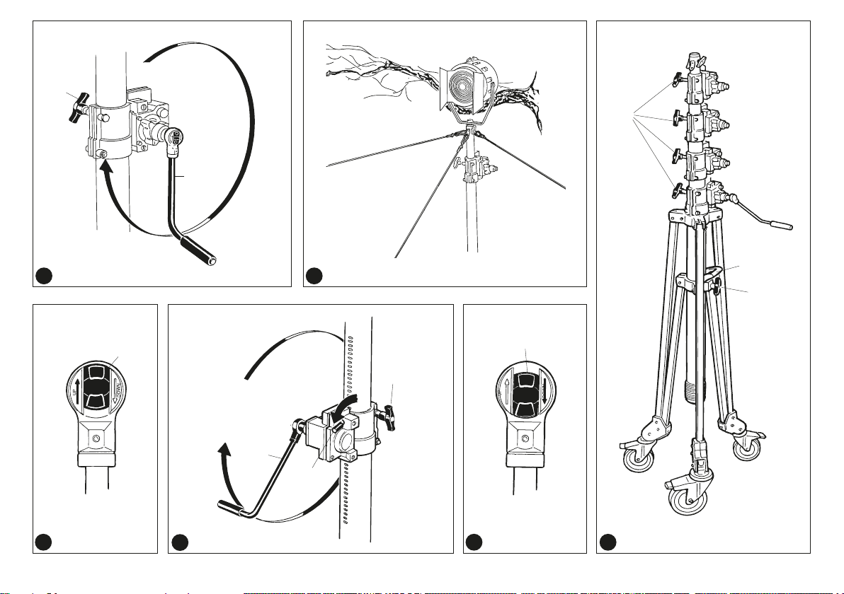
Use the handle E1 to move the stand.
7.3 After long periods of storage we recommend a thorough cleaning of the stand, see instruction
“Maintenance”.
MAINTENANCE AND SERVICE TIPS
Regularly remove dirt and debris from the locking screws and sliding parts.
Do not use metallic or sharp tools during cleaning operations.
Regularly check the state of the stand and of the crankcases by moving the columns without load.
8.1 OPERATING IN A SANDY LOCATION (BEACHES, DESERT, ETC.)
Remove lubricating grease from joints, threads and bearings to prevent sand mixing with the grease
adversely aecting the operation of the stand (g. 15).
8.2 MUDDY AND SALTY LOCATION
Before the stand is used in a muddy or salty environment, all joints, threads, moving parts of the
stand should be greased. After working in this environment, the stand must be thoroughly cleaned.
8.3 OPERATING IN COLD AND DAMP LOCATIONS ,
Make sure all joints threads and bearings are greased. If the stand is to be operated for a long period
at below freezing temperatures, take care to ensure the safety lever “L” (g. 15) is fully operative (as
per 5.2 and 5.3). To check this, crank the stand up a few centimetres and press down the safety lever;
repeat this action a few times to ensure it functions correctly.
If the columns or the mechanism are iced up, try to de-ice but do not expose to direct ame or use a
de-icing uid (joints and bearings could be aected by this).
8.4 WHEELS ,,,
While using the stand, especially of the stand, especially outdoors, the base is the most exposed part
to be potentially damaged so particular attention must be paid to periodic and scheduled maintenance.
8.41 Hard rubber wheels (g. 17) are supplied as standard and are recommended for studio environment.
They are tted with a brake “F” which locks both the travel and swivel movements. A periodic check
of wheel bearings and swivel joints must be undertaken. Wheel xing hole “O “.
8.42 To replace or t wheels simply loosen clamping screw “M” (g. 19) suciently to allow the wheel
to t or come out freely. Do not over tighten when wheel is in place. Replace or t wheels with column
down and without load.
8.43 This wheel carrier allows rolling the stand even when the stand legs are closed.
A hole for the fastening of the wheels “O” (g. 17) and another one for the use of a levelling jack “N”
(g. 18) are provided. The carrier should be cleaned and re-greased after being used in sandy or
muddy locations.
Gears must be greased and cleaned carefully whenever the stand is used in sandy or muddy areas.
8.5 - REMOVING A COLUMN FROM THE STAND ,,,
The columns of the stand are designed to withstand the normal rigours of location work.
In the event of damage, columns can easily be replaced.
It is also simple to modify the maximum and minimum height of the stand by adding or removing columns.
8.51 Removing a column riser.
Make sure that the stand is not loaded, that the columns are completely retracted and the wheels
locked (g. 21).
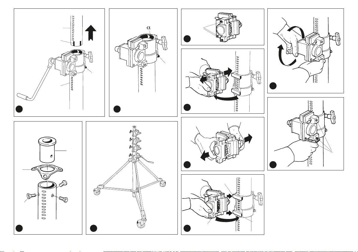
- Loosen screw “S” (g. 23) on the collar of the column.
- Pull the column “T1” (g. 21) and its collar out and whilst doing this make sure the three Teon guides
“U” (g. 21) are not left inside the column “T2” (g. 21).
- Place wire attachment plate “Z” (g. 24) mounting the top bushing “V” and secure it with the three
screws “W”.
8.52 Adding a column riser.
Make sure that the stand is not loaded, that the columns are all completely retracted and the wheels locked.
- Remove the screws “W” (g. 22) holding the eyelets “Z” and take the spotlight socket “V” out from
the top riser.
- Remove the tape on the Teon guides at the base of the column extension.
- Insert the column collar over the stand top column and then insert the extension column into the
collar making sure the Teon guides “U” (g. 21) do not fall out.
- Make sure the collar is resting fully on the lower column, use a plastic tip hammer if necessary but
make sure the Teon ring “α” (g. 23) on the inside of the collar is not displaced.
- Tighten screw “S” (g. 23). Mount the crank case on the collar (as explained in “Fitting the crank case”).
8.53 Troubleshooting
- Check the extension column functions without a load. If the column does not function properly,
check the following.
- The Teon guides “U” on the column have not been inserted correctly causing the column to jam.
- The Teon ring “α” on the inside of the collar has been displaced preventing the column being cranked.
- If the column moves in an irregular fashion when cranked down (without a luminaire), the collar
needs to be realigned and/or readjusted.
8.6 CRANKCASE
The design of the crank case is to provide maximum safety and functionality. The crank case should
require no maintenance but in the event of malfunction, it should be removed and returned to the
nearest dealer. If the malfunction is caused by damage to the outer case this will invalidate the warranty.
8.7 REMOVING THE CRANK CASE , ,
Before removing a crankcase make sure all columns are fully retracted (g. 24) and that the wheels
are locked.In addition, the stand must not be loaded.
Loosen (do not remove) the three screws “Y” (g. 25) on the side of the case and remove the crankcase
from its support (g. 26).
8.8 FITTING THE CRANK CASE , , , ,
Make sure all columns are retracted and the stand is not loaded.
- Loosen the three screws “Y” (g. 25) on the side of the crankcase. Place the case on the “dovetail”
support (g. 28), widening it a little as shown in (g. 27) and swing it in “from X1 to X2” (g. 28).
Whilst doing so ensure the gear teeth “X3” (g. 28) t into the holes in the column (g. 29).
- When the crankcase is correctly seated the three screws “Y” (g. 30) must be tightened.
Check that the crankcase functions correctly without a load.

10
GB GB
The column must move without any resistance and without any great application of force.
If this is not possible, remove the crankcase and re-t.
PRECAUTIONS
Do not use the product beyond the dened operating limitations.
Do not tamper with or modify the product or parts thereof as doing so would compromise the product’s
operation and/or safety. Using a product that has been damaged, for example due to impact or accidental
falls may compromise its safe use. In such cases, contact your retailer or the manufacturer directly
through the customer service section on manfrotto.com. Dry the product after use in damp conditions
to avoid triggering corrosion especially when using it near marine environments. The product is not
designed to be used immersed in liquids.
The stand must not be left unattended or accessible to non-professionals.
EXCLUSION OF LIABILITY
The information contained in this document may be subject to variations over time.
If necessary, please check for updates to this manual in the Products area of the manfrotto.com web
site or request an updated copy to be sent to you through the Contact us area.
Vitec Imaging Solutions cannot be held liable for any damage that may, directly or indirectly, derive
from people, things or animals, as a consequence of the non-observance of all the instructions in this
document (in particular regarding installation, use and maintenance of the product), as well as injuries
and damages resulting from improper use or use that goes beyond the normal operating limitations.
Any variation or change made to the product without explicit permission from Vitec Imaging Solutions
shall automatically result in the exclusion of any liability on Vitec Imaging Solutions’ part.
USER INFORMATION
Product disposal and packaging
Materials used
Stand: The main structure is made of aluminium and steel; rubber protection
Packaging: Paper, cardboard, polystyrene inserts, polyethylene bags
To dispose of the product and its packaging, please refer to the regulations in force in the country in
which the product is being disposed of for the aforementioned materials.
Thank you for purchasing a Vitec Imaging Solutions product.
Vitec Imaging Solutions guarantees that its products are suitable for the purpose for which they were
designed and free from defects in materials and workmanship. This warranty does not cover the
product against damage or improper use.
The duration of the Standard Warranty period is dened by the legislation in force in the country, state
or region in which the product is sold.
Please keep a copy of your product’s proof of purchase, as it will be requested in case of repair.
How to extend the warranty coverage
In addition to the mandatory standard cover referred to above, Vitec Imaging Solutions oers a warranty
extension of up to 5 years from this product’s date of purchase. The warranty extension does not aect
standard mandatory coverage. To benet from the warranty extension, you are required to register
your purchase on our web site: https://warranty.vitecimagingsolutions.com.
CONTENT OF EU DECLARATION OF CONFORMITY for B150-1 – B150P-1 – B7047CS-1 -
B7043CS-1
Manufacturer’s name: Vitec Imaging Solutions Spa
Manufacture’s address: Via Valsugana 100, 36022 Cassola (VI), Italy
Product name: STRATO-SAFE CRANK-UP STD 4 RSR
Product code: B150-1
Product name: STRATO SAFE WITH FILLED WHEELS
Product code: B150P-1
Product name: STRATO SAFE 47
Product code: B7047CS-1
Product name: STRATO SAFE 43
Product code: B7043CS-1
*Please note the B7018 STRATO SAFE 18 does not hold TÜV-GS or CE certication at the time of
this revision to the user manual
GB - Complies with the requirements of the following directives and carries “CE” marking accordingly:
I - È conforme alle seguenti direttive e riporta la marchiatura “CE”:
D - Erfüllt die folgenden Richtlinien und trägt „CE“-Zeichen entsprechend :
F - Est conforme aux directives suivantes et porte la marque « CE » en conséquence :
E - Cumple con las siguientes directivas y lleva marca “CE”:
Directive 2006/42/EC
Copyright © Vitec Imaging Solutions 2019
The legal entity authorised to compile the technical le is Vitec Imaging Solutions Spa

11
I I
USO PREVISTO
Gli stativi della linea Strato Safe sono progettati per supportare apparecchi di illuminazione per
produzioni video cinematograche e televisive in esterna o in studio.
Questo prodotto è destinato esclusivamente all’uso professionale.
SPECIFICHE TECNICHE
SPECIFICHE PER L’UTILIZZO IN SICUREZZA
1. Assicurarsi di leggere attentamente queste istruzioni prima di utilizzare il prodotto.
2. Rispettare la portata massima indicata nella tabella delle speciche tecniche.
3. Range di temperatura di utilizzo -20 °C - +60 °C
4. Questo prodotto deve essere utilizzato esclusivamente da personale esperto.
5. Assicurarsi che il terreno su cui viene utilizzato il prodotto sia stabile e che sia in grado di supportate
il peso dello stativo e del carico dell’equipaggiamento montato su di esso.
6. Accertarsi che la colonna centrale sia perfettamente livellata sulla verticale prima di sollevare
qualsiasi carico ad essa applicato.
7. Non regolare la base quando è montato e/o sollevato un carico.
8. Prima di posizionare lo stativo e di tentare qualunque tipo di regolazione/movimento dello stativo,
accertarsi che non vi siano ostacoli, materiale elettrico, cavi o altro che possa porre un rischio per
la sicurezza nell’area di ingombro dallo stativo e dal suo carico.
9. Accertarsi che l’attrezzatura montata sia bloccato correttamente sull’attacco superiore e che sia
del tutto stabile.
10. Gli stativi della linea Strato Safe sono progettati per sostenere apparecchi di illuminazione.
11. Tutti i carichi devono essere bilanciati, in particolare quando si utilizzano barre a T.
12. Durante l’utilizzo all’aperto, se l’altezza supera i 2,2 m, si raccomanda di stabilizzare il prodotto
utilizzando cavi di ancoraggio e/o kit per controventatura (087WBK, non incluso nel B7018).
13. Controllare periodicamente che lo stativo sia in buone condizioni (vedere il capitolo “MANUTENZIONE”).
MOD B7018 B7043CS-1 B7047CS-1 B150P-1 B150-1
Lunghezza minima (cm) 105 155 172 201 190
Lunghezza massima (cm) 175 427 467 621 610
Lunghezza da chiuso (cm) 126 185 209 236 225
Diametro di ingombro (cm) 120 182 213 213 213
Peso (Kg) 27 60 62 93.4 76
Carico massimo (Kg) 100 70 70 70 70
Dimensioni attacco (mm) 28 28 28 28 28
Sezioni 2 4 4 5 5
14. Non lasciare il prodotto incustodito quando si lavora in aree accessibili in cui altre persone
potrebbero interferire con lo stativo.
AMBIENTE DI UTILIZZO ,
Il trasporto e la movimentazione dello stativo devono essere eseguiti da almeno due operatori
e in conformità con le normative inerenti la movimentazione dei carichi.
Qualora serva spostare lo stativo utilizzando un verricello o altra attrezzatura di sollevamento,
sollevare o abbassare lo stativo con una cinghia per imbracatura (non in dotazione) fatta passare
intorno alla crociera superiore, come illustrato in (g 1).
Durante il sollevamento o l’abbassamento, vericare che lo stativo sia ben bilanciato e che le
gambe di appoggio siano chiuse. Non caricare mai le imbracature oltre la loro portata massima
e vericare che siano ssate correttamente allo stativo e all’attrezzatura di sollevamento.
1.2 Lo stativo deve essere utilizzato su superci piane di appoggio.
1.3 Lo stativo deve essere montato su un terreno solido in grado di sopportare sia il peso dello stativo
che il peso del carico senza che nessuna ruota aondi nel terreno, in quanto causerebbe il ribaltamento
dello stativo. Se il terreno è soce posizionare una tavola “B” (g.2) sotto le ruote.
PREPARAZIONE DELLO STATIVO , ,
2.1 2.1 Dopo aver controllato che lo stativo poggi su un terreno stabile, sganciare i fermi delle
ruote, se bloccati “F” (g. 4). Sbloccare la manopola “E” (g. 4) e spingere verso il basso l’anello la
crociera inferiore della colonna centrale in modo che le gambe di appoggio dello stativo si aprano
completamente, quindi stringere la manopola “E” (g. 4) per bloccarle in posizione. Le ruote dello
stativo devono essere bloccate “F” prima di applicare il carico (g. 4). Accertarsi che lo stativo sia in
piano utilizzando la bolla di livellamento sulla crociera.
È fondamentale mettere in piano lo stativo PRIMA di caricare l’attrezzatura.
Quando si prepara lo stativo, fare attenzione al rischio di pizzicamento/schiacciamento dovuto
al movimento delle gambe di appoggio o di altre parti.
2.2 Per gli stativi utilizzati ad altezze oltre i 2,2 m o in condizioni di vento, utilizzare il kit per controventatura
“D” (g. 3), tale kit deve essere utilizzato sempre quando la forza orizzontale del vento sul gruppo di
illuminazione supera il valore di 3,5 kg (35 N). L’utente è responsabile dell’ancoraggio a terra dei cavi
di controventatura e dovrà pertanto valutare la soluzione migliore per ssare i tiranti tramite picchetti
da terra o zavorre (non in dotazione) a seconda della conformazione del terreno.
CARICAMENTO DELLO STATIVO , ,
3.1 Accertarsi che le ruote dello stativo siano bloccate correttamente, come descritto nella sezione 2.1.
3.2 Tutte le sezioni dello stativo devono essere abbassate e le manopole “G” (g. 4) serrate.
3.3 Controllare per accertarsi che la manopola di bloccaggio dell’attacco “H” (g. 5) sia abbastanza
allentata per consentire di inserire un perno da 28 mm (1 1/8”) nella parte superiore dello stativo.

12
3.4 Dopo che il carico è stato montato sullo stativo, bloccarlo saldamente serrando la manopola “H” (g. 5).
3.5 Tutti i carichi devono essere bilanciati, in particolare quando si utilizzano barre a T (g. 6).
3.6 In condizioni di vento, si raccomanda di non caricare lo stativo con prodotti dalla supercie ampia,
come gli schermi (buttery frames o Fabbrics).
INNALZAMENTO DELLE SEZIONI DELLO STATIVO , ,
4.1 Prima di alzare lo stativo con il carico, accertarsi che sia posizionato correttamente e che il carico
sia bilanciato e bloccato (come descritto al paragrafo 3.2). Accertarsi che lo stativo non incontri ostacoli
quando viene alzato no all’altezza desiderata. Alzare sempre prima la sezione superiore, quindi la
successiva a scendere, no a raggiungere l’altezza desiderata.
Controllare che gli apparecchi di illuminazione non siano alimentati quando si solleva o si
abbassa lo stativo e che i cavi elettrici di alimentazione non siano a contatto con gli organi di
sollevamento, al ne di evitare che vengano tagliati o pizzicati accidentalmente.
Accertarsi di aver serrato correttamente la manopola “H” per impedire la caduta accidentale su
persone o le cose sottostanti.
4.3 Montare la manovella “J” (g. 8) nella scatola di ingranaggio e sbloccare la manopola “G” (g. 8)
della sezione da sollevare. Il tasto “I” (g. 9) sulla manovella deve essere nella posizione superiore.
Ruotare la manovella in senso orario no a raggiungere l’altezza richiesta.
4.4 Serrare la manopola “G” (g. 8) per accertarsi che ogni sezione sollevata sia ssata, per impedire
che ruoti quando si trova all’altezza desiderata. Vericare che i cavi di sicurezza (g. 7) siano
ssati, in particolare ad altezze superiori a 2,2 metri, in condizioni di vento, se lo stativo si trova su
un’impalcatura o altro.
NON SPOSTARE LO STATIVO DOPO CHE IL CARICO È STATO SOLLEVATO.
Non usare le gambe di appoggio o altre parti dello stativo come rialzi su cui salire.
4.5 Nota: se si riscontrano dicoltà nel sollevare le sezioni, controllare che:
- La manopola di bloccaggio “G” (g. 8) non sia allentata.
- Il carico non superi la portata specicata per lo stativo.
- Nessuna delle sezioni abbia subito danni durante il trasporto.
- Non vi siano ostacoli (sotto, balaustre, ecc.).
ABBASSAMENTO DELLE SEZIONI DELLO STATIVO , ,
5.1 Assicurarsi che non vi siano ostacoli prima di abbassare lo stativo (g. 10).
Abbassare le sezioni iniziando da quella inferiore e quindi la successiva a salire, in ordine contrario
a quanto fatto per l’innalzamento.
Controllare che gli apparecchi di illuminazione non siano alimentati quando si solleva o si
abbassa lo stativo e che i cavi elettrici di alimentazione non siano a contatto con gli organi di
sollevamento, al ne di evitare che vengano tagliati o pizzicati accidentalmente.
5.2 Allentare la manopola “G” (g. 11) sulla sezione da abbassare per prima e inserire la manovella
I I
“J” (g. 11) nella scatola di ingranaggio. Sollevare la sezione di 2 cm per consentire il disinnesto del
fermo di sicurezza secondario abbassando la leva “L” (g. 11).
5.3 Mentre si preme la leva “L” (g. 11) verso il basso, portare il tasto sulla manovella nella posizione
inferiore e ruotare la manovella in senso antiorario.
5.4 Se la leva di sicurezza “L” (g. 11) viene lasciata la sezione si blocca in sede automaticamente.
Al ne di abbassare lo stativo all’altezza richiesta, ripetere i passaggi 5.2 e 5.3.
5.5 Quando le sezioni sono abbassate, serrare tutte le manopole di fermo delle sezioni “G” (g. 11).
5.6 Nota: se si riscontrano dicoltà nell’abbassare le sezioni, controllare che:
- La manopola di bloccaggio “G” (g. 11) non sia allentata.
- Le sezioni o le scatole di ingranaggio non abbiano subito danni durante il trasporto.
- Non vi siano ostacoli (sotto, balaustre, ecc.).
SPOSTAMENTO DI UN CARICO CONDIVISO SU DUE STATIVI
6.1 Prima di sollevare lo stativo caricato, assicurarsi che sia posizionato correttamente secondo
quanto descritto ai capitoli PREPARAZIONE DELLO STATIVO e CARICAMENTO DELLO STATIVO
6.2 La barra che porta il carico condiviso deve essere in orizzontale.
La scelta della barra e delle sue caratteristiche tecniche è di esclusiva responsabilità dell’utente
nale. Vitec Imaging Solutions non sarà ritenuta responsabile per danni a persone, cose o
animali, derivanti dalla scelta erronea della barra.
6.3 Il carico deve essere:
- Correttamente bilanciato ed ugualmente distribuito sui due stativi.
- Bloccato con la manopola “H” (g. 5).
- Entro la portata massima dello stativo.
6.4 Il sollevamento di due stativi deve essere eseguito da due operatori, attenendosi alle istruzioni
fornite nel capitolo “INNALZAMENTO DELLE SEZIONI DELLO STATIVO”.
6.5 Accertarsi che la velocità di sollevamento delle sezioni sia la stessa per entrambi gli stativi anché
la barra rimanga in orizzontale.
6.6 Assicurarsi che non vi siano ostacoli prima di abbassare lo stativo.
6.7 L’abbassamento dei due stativi deve essere eseguito da due operatori, attenendosi alle istruzioni
fornite nel capitolo “ABBASSAMENTO DELLE SEZIONI DELLO STATIVO”.
6.8 Accertarsi che la velocità di abbassamento delle sezioni sia la stessa per entrambi gli stativi
anché la barra rimanga in orizzontale.
STOCCAGGIO
7.1 Tutte le sezioni devono essere abbassate e bloccate. Bloccare anche la manopola “E” (g. 13).
7.2 Allentare la manopola “E” (g. 13) quindi, utilizzando la maniglia sulla crociera inferiore della colonna

13
I I
centrale, tirare verso l’alto no a quando le gambe di appoggio sono chiuse. Lo stativo è progettato
per essere movimentato sulle ruote in posizione chiusa (se le ruote sono montate).
Il trasporto e la movimentazione dello stativo devono essere eseguiti da almeno due operatori
in conformità con le norme di sicurezza.
È più sicuro aprire leggermente la base dello stativo per ridurre il rischio di ribaltamento.
Vericare che sul percorso non vi siano ostacoli che potrebbero ostruire il passaggio o far
ribaltare lo stativo.
Usare la maniglia E1 per spostare lo stativo.
7.3 Dopo lunghi periodi di inutilizzo si raccomanda una pulizia accurata dello stativo, vedere le istruzioni
nel capitolo “Manutenzione”.
MANUTENZIONE E SUGGERIMENTI PER L’ASSISTENZA
Eliminare regolarmente sporco e materiale estraneo dalle viti di bloccaggio e dalle parti scorrevoli.
Non utilizzare strumenti di metallo o appuntiti per le operazioni di pulizia. Controllare periodicamente
le condizioni dello stativo e delle scatole di ingranaggio muovendo le sezioni senza carico.
8.1 USO IN LUOGHI CON SABBIA (SPIAGGIA, DESERTO, ECC.)
Rimuovere il grasso lubricante dai collegamenti, dai letti e dai cuscinetti per evitare che la sabbia
si mescoli al grasso compromettendo il funzionamento dello stativo (g. 15).
8.2 USO IN LUOGHI CON FANGO E SALSEDINE
Prima di utilizzare lo stativo in un ambiente con fango o salsedine, ingrassare tutti i collegamenti, i letti
e le parti in movimento dello stativo. Dopo aver lavorato in ambienti di questo tipo, è necessario pulire
accuratamente lo stativo.
8.3 USO IN LUOGHI FREDDI E UMIDI ,
Accertarsi che tutti i letti, collegamenti e i cuscinetti siano lubricati. Se lo stativo deve essere utilizzato
per un lungo periodo a temperature al di sotto dello zero, accertarsi che la leva di sicurezza “L” (g.
15) funzioni perfettamente (come indicato ai paragra 5.2 e 5.3). Per vericare, sollevare lo stativo
di qualche centimetro e spingere verso il basso la leva di sicurezza; ripetere l’operazione alcune
volte per accertarsi che funzioni correttamente. Se le sezioni o il meccanismo si gelano, provare a
sciogliere il ghiaccio, ma non esporli a amma diretta né utilizzare liquido scongelante, che potrebbe
rovinare i collegamenti e cuscinetti.
8.4 RUOTE ,,,
Quando si utilizza lo stativo, in particolare all’esterno, la base è la parte più esposta a potenziali danni,
per questo è necessario prestare particolare attenzione alla manutenzione periodica e programmata.
8.41 Le ruote in gomma dura (g. 17) sono fornite di serie e sono raccomandate per l’utilizzo in studio.
Sono dotate di un freno “F” che blocca i movimenti di avanzamento e di rotazione. È necessario
controllare periodicamente i cuscinetti delle ruote e gli snodi. Foro di ssaggio della ruota “O”.
8.42 Per sostituire o montare le ruote è suciente allentare le viti di ssaggio “M” (g. 19) quanto basta
per poter inserire o estrarre agevolmente la ruota. Non serrare eccessivamente quando la ruota è in
sede. Quando si sostituiscono o si montano le ruote, le sezioni devono essere abbassate e senza carico.
8.43 L’articolazione della staa porta ruota consente di spostare lo stativo sulle ruote anche quando le
gambe di appoggio sono chiuse. Sono predisposti un foro per serrare le ruote “O” (g. 17) e un altro
per utilizzare il levelling jack “N” (g. 18). La staa porta ruota deve essere pulita e lubricata dopo
l’utilizzo in luoghi con sabbia o fango. Gli ingranaggi devono essere ingrassati e puliti accuratamente
ogni volta che si usa lo stativo su terreni fangosi o sabbiosi.
8.5 RIMOZIONE DI UNA SEZIONE DALLO STATIVO ,,,
Le sezioni dello stativo sono progettate per resistere ai normali rigori di un set di lavorazione. Nel caso
in cui siano danneggiate, si possono facilmente sostituire.
Inoltre, è semplice modicare l’altezza massima e minima dello stativo aggiungendo o togliendo sezioni.
8.51 Rimozione di un alzata di sezione
Accertarsi che non vi sia un carico sullo stativo, che le sezioni siano completamente chiuse e che le
ruote siano bloccate (g. 21).
- Allentare la vite “S” (g. 23) sul colletto della colonna.
- Estrarre la sezione “T1” (g. 21) e il relativo colletto avendo cura di accertarsi che le tre guide in
Teon “U” (g. 21) non restino all’interno della sezione “T2” (g. 21).
- Posizionare la piastra di attacco dei cavi “Z” (g. 24) inserendo la boccola superiore “V” e ssarla
con le tre viti “W”.
8.52 Aggiunta di un’alzata di sezione
Accertarsi che non vi sia un carico sullo stativo, che le tutte le sezioni siano completamente abbassate
e che le ruote siano bloccate.
- Rimuovere le viti “W” (g. 22) che trattengono gli occhielli “Z” ed estrarre l’attacco superiore “V”
dall’alzata superiore.
- Rimuovere il nastro dalle guide in Teon sulla base della prolunga della sezione.
- Inlare il colletto della sezione sulla sezione superiore dello stativo, quindi inserire la prolunga nel
colletto facendo attenzione che le guide in Teon “U” (g. 21) non si stacchino.
- Accertarsi che il colletto sia completamente in sede sulla sezione inferiore, utilizzare un martello
con la punta di plastica, se necessario, ma accertarsi che l’anello di Teon “α” (g. 23) all’interno
del colletto non si sposti.
- Serrare la vite “S” (g. 23). Montare il meccanismo a cricchetto sul colletto, come descritto in
“Montaggio del meccanismo a cricchetto”.
8.53 Risoluzione dei problemi
- Controllare che la sezione di prolunga funzioni senza carico. Se la sezione non funziona correttamente,
controllare queste possibili cause:
- Le guide in Teon “U” sulla sezione non sono state inserite correttamente e la sezione si inceppa.
- L’anello in Teon “α” all’interno del colletto si è spostato e impedisce il movimento della sezione.
- Se la sezione si muove in modo irregolare quando viene abbassata (senza un apparecchio di
illuminazione applicato), è necessario riallineare e/o regolare di nuovo il colletto
8.6 SCATOLA DI INGRANAGGIO
La progettazione della scatola di ingranaggio è pensata per orire la massima sicurezza e funzionalità.
La scatola di ingranaggio non necessita di manutenzione, tuttavia nel caso di malfunzionamento deve
essere rimosso e portato al concessionario più vicino. Un malfunzionamento dovuto al danneggiamento
della cassa esterna rende nulla la garanzia.

14
I I
8.7 RIMOZIONE DELLA SCATOLA DI INGRANAGGIO , ,
Prima di rimuovere la scatola di ingranaggio accertarsi che tutte le sezioni siano completamente
abbassate (g. 24) e che le ruote siano bloccate. Inoltre non devono essere presenti carichi sullo stativo.
Allentare (senza rimuoverle) le tre viti “Y” (g. 25) sul lato della scatola degli ingranaggi e rimuovere
la scatola di ingranaggio dal suo supporto (g. 26).
8.8 APPLICAZIONE DELLA SCATOLA DI INGRANAGGIO , , , ,
Accertarsi che tutte le sezioni siano abbassate e che non vi sia un carico sullo stativo.
- Allentare le tre viti “Y” (g. 25) sul lato della scatola di ingranaggio. Posizionare il supporto a coda
di rondine (g. 28) allargandolo leggermente, come illustrato in (g. 27) e inserirlo con un movimento
graduale da X1 a X2 (g. 28). Durante questa operazione accertarsi che i denti dell’ingranaggio “X3”
(g. 28) si inseriscano nei fori della sezione (g. 29).
- Quando la scatola di ingranaggio è correttamente in sede, le tre viti “Y” (g. 30) devono essere serrate.
Controllare che la scatola di ingranaggio funzioni correttamente senza carico. La sezione deve
muoversi senza opporre resistenza e senza applicare molta forza. Se ciò non è possibile, rimuovere
la scatola di ingranaggio e reinstallarla.
PRECAUZIONI
Non usare il prodotto oltre i range operativi specicati. Non manomettere e non modicare il prodotto
o le sue parti in quanto si potrebbe compromettere il funzionamento del prodotto e/o la sicurezza.
L’uso di un prodotto che ha subito un danno, ad esempio per un urto o una caduta accidentale
può comprometterne l’utilizzo in sicurezza. In tali evenienze, contattare il rivenditore o il produttore
direttamente tramite la sezione dell’assistenza clienti su manfrotto.com. Asciugare il prodotto dopo
averlo utilizzato in condizioni di umidità per evitare che si avviino processi di corrosione, in particolare in
caso di utilizzo vicino ad ambienti marittimi. Il prodotto non è progettato per essere immerso nei liquidi.
Lo stativo non deve essere lasciato incustodito o accessibile a personale estraneo.
ESCLUSIONE DI RESPONSABILITÀ
Le informazioni contenute in questo documento possono essere soggette a variazioni nel tempo.
All’occorrenza, vericare se sono presenti aggiornamenti del manuale nell’area Prodotti del sito
manfrotto.com o richiedere l’invio di una copia aggiornata tramite l’area Contattaci. Vitec Imaging
Solutions non potrà essere ritenuta responsabile di qualsiasi danno che possa derivare, direttamente
o indirettamente, a persone, cose o animali, in conseguenza dell’inosservanza di tutte le indicazioni
contenute nel presente documento (in particolare per quanto riguarda l’installazione, l’uso e la
manutenzione del prodotto) né di lesioni e danni derivanti da un uso o uso improprio che va oltre le
normali limitazioni di utilizzo.
Qualsiasi variazione o modica apportata al prodotto senza l’autorizzazione esplicita di Vitec Imaging
Solutions comporta automaticamente l’esclusione di qualsiasi responsabilità di Vitec Imaging Solutions.
INFORMAZIONI PER L’UTENTE
Smaltimento e imballaggio del prodotto
Materiali usati
Stativo: la struttura principale è realizzata in alluminio e acciaio; protezione in gomma
Imballo: carta, cartone, inserti in polistirolo, buste in polietilene
Per lo smaltimento del prodotto e del suo imballaggio, fare riferimento alle normative vigenti nel paese
CONTENUTO DELLA DICHIARAZIONE DI CONFORMITÀ per B150-1 – B150P-1 – B7047CS-1 -
B7043CS-1
Nome del produttore: Vitec Imaging Solutions Spa
Indirizzo del produttore: Via Valsugana 100, 36022 Cassola (VI), Italy
Nome prodotto: STRATO-SAFE CRANK-UP STD 4 RSR
Codice prodotto: B150-1
Nome prodotto: STRATO SAFE WITH FILLED WHEELS
Codice prodotto: B150P-1
Nome prodotto: STRATO SAFE 47
Codice prodotto: B7047CS-1
Nome prodotto: STRATO SAFE 43
Codice prodotto: B7043CS-1
*Si tenga presente che il prodotto B7018 STRATO SAFE 18 non è provvisto di certicazione TÜV-GS
o CE al momento di questa revisione del manuale per l’utente.
GB - Complies with the requirements of the following directives and carries “CE” marking accordingly:
I - È conforme alle seguenti direttive e riporta la marchiatura “CE”:
D - Erfüllt die folgenden Richtlinien und trägt „CE“-Zeichen entsprechend :
F - Est conforme aux directives suivantes et porte la marque « CE » en conséquence :
E - Cumple con las siguientes directivas y lleva marca “CE”:
Direttiva 2006/42/CE
Copyright © Vitec Imaging Solutions 2019
La persona giuridica autorizzata a compilare il le tecnico è Vitec Imaging Solutions Spa
in cui il prodotto viene smaltito relativamente ai materiali sopra menzionati.
Grazie per aver acquistato un prodotto Vitec Imaging Solutions.
Vitec Imaging Solutions garantisce che i suoi prodotti sono idonei allo scopo per il quale sono stati
progettati e che sono privi di difetti nei materiali e nella fabbricazione. Questa garanzia non copre il
prodotto da danni o uso improprio. La durata del periodo di Garanzia Standard è denita dalla legislazione
in vigore nel paese, nello stato o nell’area geograca in cui il prodotto è venduto.
Conservare una copia della prova d’acquisto del prodotto, che sarà richiesta in caso di riparazione.
Estensione della garanzia
Oltre alla copertura standard obbligatoria di cui sopra, Vitec Imaging Solutions ore un’estensione della
garanzia no a 5 anni dalla data di acquisto del prodotto. L’estensione della garanzia non altera la
copertura obbligatoria standard. Per beneciare dell’estensione della garanzia, è necessario registrare
l’acquisto sul nostro sito web: https://warranty.vitecimagingsolutions.com.

15
DE DE
BESTIMMUNGSGEMÄSSER GEBRAUCH
Die Stative der Strato Safe Familie sind zum Tragen von Beleuchtung für Film- und Fernsehproduktionen
im Studio oder bei Außenaufnahmen konstruiert.
Das Produkt ist ausschließlich für den professionellen Einsatz vorgesehen.
TECHNISCHE SPEZIFIKATIONEN
ANWEISUNGEN ZUM SICHEREN EINSATZ
1. Lesen Sie diese Anleitung unbedingt sorgfältig durch, bevor Sie das Produkt verwenden.
2. Halten Sie die in der Tabelle mit den technischen Daten angegebene maximale Traglast ein.
3. Betriebstemperaturbereich -20°C bis +60°C
4. Dieses Produkt sollte ausschließlich von erfahrenem Personal eingesetzt werden.
5. Stellen Sie sicher, dass der Boden fest ist, auf dem das Produkt eingesetzt werden soll und das
Gewicht des Stativs samt der befestigten Traglast aushält.
6. Stellen sie sicher, dass die Mittelsäule perfekt im Lot ist, bevor Sie versuchen, daran befestigte
Ausrüstung anzuheben.
7. Nehmen Sie bei montierter/gehobener Last keine Einstellungen an der Basis vor.
8. Stellen Sie vor dem Positionieren des Gestells und irgendwelchen Versuchen, das Gestell einzustellen
oder zu bewegen sicher, dass sich keine Hindernisse wie Kabel oder sonstige Gefahren im Weg
des Stativs und seiner Last benden.
9. Stellen sie sicher, dass die Traglast ordnungsgemäß fest in der Buchse an der Säulenspitze sitzt
und vollständig stabil ist.
10. Die Stative der Strato Safe Familie sind für das Aufstellen von Beleuchtung ausgelegt.
11. Alle Lasten sollten sich im Gleichgewicht benden, besonders bei Nutzung von Quertraversen (T-Bars).
12. Beim Einsatz im Freien mit Höhen über 2,2 m wird empfohlen, Ankerseile und/oder Sicherungs-
Kits (087WBK, separat erhältlich) gegen Wind zu verwenden.
13. Prüfen Sie regelmäßig den ordnungsgemäßen Zustand des Stativs (siehe Kapitel WARTUNG
und TIPPS ZUR INSTANDHALTUNG).
MOD B7018 B7043CS-1 B7047CS-1 B150P-1 B150-1
Minimale Länge (cm) 105 155 172 201 190
Maximale Länge (cm) 175 427 467 621 610
Länge zusammengeklappt (cm) 126 185 209 236 225
Durchmesser der Stelläche (cm) 120 182 213 213 213
Gewicht (Kg) 27 60 62 93.4 76
Maximale Traglast (Kg) 100 70 70 70 70
Durchmesser der Buchse (mm) 28 28 28 28 28
Segmente 2 4 4 5 5
14. Das Stativ bei Arbeiten in belebten Bereichen niemals unbeaufsichtigt lassen, wenn sich Unbefugte
daran zu schaen machen könnten.
EINSATZUMGEBUNG ,
Transport und Handhabung des Stativs sind durch mindestens zwei Personen gemäß den
Vorschriften für den Lasttransport durchzuführen.
Um das Stativ mit einer Winde oder anderen Hubvorrichtungen zu versetzen, ein Gurtband
(nicht im mitgeliefert) um den Hauptring für die Beinstreben legen, wie in (Abb. 1) dargestellt.
Beim Anheben oder Absetzen sicherstellen, dass das Stativ gut ausbalanciert ist und dass die
Beine eingeklappt sind. Gurtbänder niemals über deren Tragkraft hinaus belasten und stets
prüfen, dass sie korrekt am Stativ und am Hebezeug befestigt sind.
1.2 Das Stativ darf nur auf horizontal ebenen Oberächen benutzt werden.
1.3 Das Stativ muss auf festem Boden aufgestellt werden, der das Gewicht von Stativ samt Traglast
aushält, ohne dass eine der Rollen einsinkt, was zum Umkippen das Stativs führen kann. Wenn der
Boden zu weich ist, ein Brett B (Abb. 2) unter der Rolle platzieren.
AUFSTELLEN DES STATIVS , ,
2.1 Nachdem geprüft wurde, dass das Stativ auf festem Boden steht, die Bremsen F (Abb. 4) lösen, falls
Rollen montiert sind. Die Knebelschraube E (Abb. 4) lösen und das unterste zentrale Gussstück an der
Säule herunterschieben, bis die Beine des Stativs vollständig geönet sind. Dann die Knebelschraube
E (Abb. 4) anziehen, um es zu xieren. Die Rollen des Stativs müssen mit den Bremsen F (Abb. 4)
blockiert werden, bevor eine Last befestigt wird. Mit der Wasserwaage kontrollieren, dass die Säule
lotrecht steht.
Das Stativ muss unbedingt senkrecht stehen, BEVOR die Ausrüstung befestigt wird.
Beim Aufstellen des Stativs auf die Gefahr von Quetschungen oder Einklemmen durch die
Bewegung der Beine oder anderer Teile achten..
2.2 Bei Stativhöhen über 2,2 m oder bei windigen Bedingungen sollte das Sicherungs-Kit D (Abb. 3)
verwendet werden, das ab einer horizontalen Windlast von über 3,5 kg (35 N) auf den Beleuchtungskörper
immer eingesetzt werden sollte. Das Verankern der Abspannseile im Boden liegt in der Verantwortung
des Nutzers, der die beste Lösung zum Befestigen der Sicherungen mit Erdnägeln oder Ankern (nicht
mit dem Produkt geliefert) anhand der Bodenbedingungen abwägen muss.
BELADEN DES STATIVS , ,
3.1 Stellen Sie sicher, dass die Rollen des Stativs korrekt blockiert sind, wie unter 2.1. beschrieben.
3.2 Alle Säulensegmente müssen abgesenkt und die Knebelschrauben G (Abb. 4) angezogen sein.
3.3 Kontrollieren Sie, dass die Knebelschraube H (Abb. 5) so weit herausgedreht ist, dass ein 28-mm-
Stift in die Säulenspitze passt.
3.4 Sichern Sie die Traglast nach dem Aufsetzen auf das Stativ, indem Sie die Knebelschraube H
(Abb. 5) anziehen.

16
3.5 Alle Lasten sollten sich im Gleichgewicht benden, besonders beim Einsatz von Quertraversen
(T-Bars) usw. (siehe Abb. 6).
3.6 Bei Wind empfehlen wir, keine Ausrüstung am Stativ zu befestigen, die dem Wind eine große
Angrisäche bietet, wie z. B. mit Sto bespannte Klapprahmen.
ANHEBEN DER SÄULENSEGMENTE , ,
4.1 Vor dem Anheben der Last auf dem Stativ unbedingt sicherstellen, dass dieses korrekt positioniert
ist und die Last ausbalanciert und gesichert (gemäß 3.2) ist. Kontrollieren Sie, dass kein Hindernis
beim Anheben auf die gewünschte Höhe im Weg ist. Das oberste Segment der Säule immer zuerst
anheben und dann das Segment direkt darunter usw., bis die gewünschte Höhe erreicht ist
Stellen Sie sicher, dass die Beleuchtung während des Anhebens oder Absenkens nicht
eingeschaltet werden kann und dass die Elektrokabel keinen Kontakt zur Säule haben, um
Schäden zu vermeiden.
Stellen Sie sicher, dass die Knebelschraube H korrekt angezogen ist, um zu verhindern, dass
sich das Stativ und/oder Beleuchtung versehentlich lockert und umstürzt
4.3 Die Ratschenkurbel J (Abb. 8) in das Gehäuse stecken und die Knebelschraube G (Abb. 8) des
anzuhebenden Säulensegments lösen. Der Wählschalter I (Abb. 9) an der Ratsche muss sich in der
Position UP (AUF) benden. Drehen Sie die Kurbel im Uhrzeigersinn, bis die gewünschte Höhe erreicht ist.
4.4 Stellen Sie sicher, dass jedes Säulensegment gegen Verdrehen gesichert ist, indem Sie die
Knebelschraube G (Abb. 8) anziehen, nachdem die erforderliche Höhe erreicht ist.
Kontrollieren Sie, dass die Sicherungsverspannungen (Abb. 7) fest sitzen, besonders bei Höhen über
2,2 m oder bei Wind oder wenn das Stativ auf einem Gerüst steht usw.
DAS STATIV NIEMALS BEI ANGEHOBENER LAST BEWEGEN.
Die Beine oder andere Teile des Stativs nicht als Trittstufe verwenden.
4.5 Hinweis: Sollten beim Anheben der Säulensegmente Probleme auftreten, prüfen Sie folgendes:
- Wurde die Knebelschraube G (Abb. 8) gelöst.
- Übersteigt das Lastgewicht die Spezikationen des Stativs.
- Wurden Säulensegmente beim Transport beschädigt.
- Ist ein Hindernis (Decke, Balustrade usw.) im Weg.
ABSENKEN DER SÄULENSEGMENTE , ,
5.1 Stellen Sie vor dem Absenken der Säule sicher, dass keine Hindernisse im Weg sind (Abb. 10).
Die Segmente beginnend mit dem untersten absenken und erst dann das Segment direkt darüber
(umgekehrt zum Anheben).
Stellen Sie sicher, dass die Beleuchtung während des Anhebens oder Absenkens nicht
eingeschaltet werden kann und dass die Elektrokabel keinen Kontakt zur Säule haben, um
Schäden zu vermeiden.
5.2 Die Knebelschraube G (Abb. 11) am zuerst abzusenkenden Segment lösen und die Ratschenkurbel
J (Abb. 11) in das Gehäuse stecken. Das Segment um zwei Zentimeter anheben, um die sekundäre
Sicherungsverriegelung durch Herabdrücken des Hebels L (Abb. 11) entriegeln zu können.
5.3 Bei herabgedrückt gehaltenem Hebel L (Abb. 11) den Wählschalter der Ratsche in die Position
DE DE
DOWN (AB) bringen und die Kurbel gegen den Uhrzeigersinn drehen.
5.4 Wird der Sicherheitshebel L (Abb. 11) gelöst (das Segment rastet sofort automatisch ein), bevor
die Säule auf die erforderliche Höhe abgesenkt ist, die Aktionen unter 5.2 und 5.3 wiederholen.
5.5 Wenn die Segmente eingefahren sind, alle Knebelschrauben G (Abb. 11) der Segmente anziehen.
5.6 Hinweis: Sollten beim Absenken der Säulensegmente Probleme auftreten, prüfen Sie folgendes:
- Wurde die Knebelschraube G (Abb. 11) gelöst.
- Wurden Säulensegmente oder Getriebegehäuse beim Transport beschädigt.
- Ist ein Hindernis (Decke, Balustrade usw.) im Weg.
HEBEN/SENKEN EINER GEMEINSAMEN LAST MIT ZWEI STATIVEN
6.1 Stellen Sie vor dem Anheben einer Last mit den Stativen sicher, dass diese korrekt positioniert
sind, wie in den Kapiteln AUFSTELLEN DES STATIVS und BELADEN DES STATIVS beschrieben.
6.2 Die Traverse zum Heben der gemeinsamem Last muss waagerecht sein.
Die Wahl der Traverse und deren technische Belastungsfähigkeit liegen in der alleinigen Verantwortung
des Endnutzers.
Vitec Imaging Solutions übernimmt keine Haftung für irgendwelche Personen- oder Sachschäden
durch eine falsch gewählte Traverse.
6.3 Die Last muss
- korrekt ausbalanciert, gleichmäßig auf beide Stative verteilt und
- mit den Knebelschrauben H (Abb. 5) verriegelt sein.
- Die maximale Traglast der Stative darf nicht überschritten werden.
6.4 Das Anheben von zwei Säulen muss von zwei Personen gemäß den Anweisungen im Kapitel
durchgeführt werden “ANHEBEN DER SÄULENSEGMENTE”.
6.5 Stellen Sie sicher, dass beide Säulen zugleich angehoben werden, damit die Traverse horizontal bleibt.
6.6 Stellen Sie vor dem Absenken der Säulensegmente sicher, dass keine Hindernisse im Weg sind.
6.7 Das Absenken von zwei Säulen muss von zwei Personen gemäß den Anweisungen in Kapitel
durchgeführt werden “ABSENKEN DER SÄULENSEGMENTE”.
6.8 Stellen Sie sicher, dass beide Säulen zugleich abgesenkt werden, damit die Traverse horizontal bleibt.
LAGERUNG
7.1 Alle Säulensegmente sollten eingefahren und verriegelt sein. Auch die Knebelschraube E (Abb.
13) anziehen.
7.2 Die Knebelschraube E (Abb. 13) lösen und den Gri E1 am Gussteil an der Mittelsäule nutzen,
um es nach oben zu ziehen, bis die Beine eingeklappt sind. Das Stativ ist so konstruiert, dass es in
eingeklapptem Zustand gerollt werden kann (wenn Rollen montiert sind).
Transport und Handhabung des Stativs sind durch mindestens zwei Personen gemäß den
Sicherheitsvorschriften durchzuführen.

17
DE DE
Um das Risiko des Umkippens zu vermindern, ist es am sichersten, die Basis des Stativs ein
wenig zu önen.
Kontrollieren Sie, dass sich keine Hindernisse im Transportweg benden, die das Stativ blockieren
oder es umstürzen lassen könnten.
Zum Bewegen des Stativs den Gri E1 benutzen.
7.3 Nach längerer Lagerung empfehlen wir die gründliche Reinigung des Stativs, siehe die Anweisungen
unter „WARTUNG“.
WARTUNG UND TIPPS ZUR INSTANDHALTUNG
Knebelschrauben und gleitende Teile sind regelmäßig von Schmutz und Fremdkörpern zu befreien.
Keine metallischen oder scharfkantigen Utensilien zum Reinigen verwenden. Den Zustand des Stativs
und der Getriebegehäuse regelmäßig durch Ausfahren der Säulensegmente ohne Last überprüfen.
8.1 EINSATZ IN SANDIGEN UMGEBUNGEN (STRAND, WÜSTE USW.)
Schmierfett von Verbindungen, Gewinden und Lagern entfernen, um zu verhindern, dass es sich
mit Sand vermischt, wodurch das Fett die Bedienung des Stativs beeinträchtigen würde (Abb. 15).
8.2 MATSCHIGE UND SALZIGE EINSATZORTE
Vor dem Einsatz des Stativs in matschigen oder salzhaltigen Umgebungen sollten alle Verbindungen,
Gewinde und beweglichen Teile des Stativs gefettet werden. Nach einem Einsatz in solchen Umgebungen
muss das Stativ gründlich gereinigt werden.
8.3 EINSATZ IN KALTEN UND FEUCHTEN UMGEBUNGEN ,
Stellen Sie sicher, dass alle Verbindungen, Gewinde und Lager gefettet sind. Wird das Stativ über
längere Zeit bei Temperaturen unter dem Gefrierpunkt eingesetzt, sorgfältig sicherstellen, dass die
Sicherheitshebel L (Abb. 15) voll funktionsfähig sind (gemäß 5.2 und 5.3). Um dies zu überprüfen, die
Säule ein paar Zentimeter nach oben kurbeln und den Sicherheitshebel drücken. Diesen Vorgang mehrere
Male wiederholen, um sicherzustellen, dass der Hebel korrekt funktioniert. Wenn Säulensegmente
oder Mechaniken vereist sind, versuchen Sie diese aufzutauen, ohne sie jedoch einer direkten
Flamme auszusetzen oder Enteisungsüssigkeit einzusetzen (Verbindungen und Lager könnten
dadurch beeinträchtigt werden).
8.4 ROLLEN ,,,
Während des Einsatzes des Stativs (besonders im Freien) ist die Basis der Teil, der potenziellen
Beschädigungen am stärksten ausgesetzt ist, weshalb ihrer rechtezeitigen und planmäßigen Wartung
besondere Aufmerksamkeit gewidmet werden muss.
8.41 Hartgummirollen (Abb. 7) werden standardmäßig mitgeliefert und sind empfohlen für
Studioumgebungen. Sie sind mit einer Bremse (F) ausgestattet die sowohl das Abrollen als auch
das Schwenken blockiert. Es sind regelmäßige Überprüfungen der Rollenlager und Schwenklager
durchzuführen. Loch O für Rollenbefestigung.
8.42 Zum Austauschen oder Anbringen der Rollen die Klemmschraube M (Abb. 19) so weit lösen, dass
die Rolle reibungslos heraus- bzw. hineingleitet. Nicht zu stark anziehen, wenn eine Rolle montiert
ist. Der Einbau oder Austausch von Rollen muss bei abgesenkter Säule ohne Beladung erfolgen.
8.43 Die Rollenträger erlauben das Rollen des Stativs auch bei eingeklappten Beinen.
Es ist ein Loch O (Abb. 17) zum Befestigen der Rolle und ein weiteres Loch N (Abb. 18) zum Ansetzen
einer Hubvorrichtung zum Nivellieren vorhanden. Die Rollenträger sollten nach Einsatz in sandigen
oder matschigen Umgebungen gereinigt und nachgefettet werden.
Immer wenn das Stativ in sandigen oder matschigen Umgebungen eingesetzt wurde, müssen die
Zahnräder sorgfältig gereinigt und gefettet werden.
8.5 - AUSBAU EINES SÄULENSEGMENTS AUS DEM STATIV ,,,
Die Säulensegmente des Stativs sind für die normalen Belastungen bei der Arbeit am Einsatzort
ausgelegt. Werden sie beschädigt, können sie problemlos ersetzt werden.
Es ist ebenfalls ganz einfach, die Gesamthöhe des Stativs durch Hinzufügen/Entfernen von Segmenten
zu verändern.
8.51 Ausbau eines Hubsegments
Stellen Sie sicher, dass das Stativ nicht beladen ist, dass die Säule komplett eingefahren ist und dass
die Rollen blockiert sind (Abb. 21).
- Die Schraube S (Abb. 23) an der Manschette des Segments lösen.
- Das Segment T1 (Abb. 21) und dessen Manschette herausziehen und dabei darauf achten, dass
die Teonführungen U (Abb. 21) nicht im Segment T2 (Abb. 21) verbleiben.
- Die Platte Z (Abb. 22) zum Befestigen von Spannseilen aufsetzen, die oberste Buchse V einsetzen
und mit den Schrauben W sichern.
8.52 Hinzufügen eines Hubsegments
Stellen Sie sicher, dass das Stativ nicht beladen ist, dass die Säule komplett eingefahren ist und
dass die Rollen blockiert sind.
- Die Schrauben W (Abb. 22) lösen, mit der die Einhakplatte Z befestigt ist und dann die Scheinwerferbuchse
V aus dem obersten Segment entnehmen.
- Das Klebeband um die Teonführungen am unteren Ende des Säulensegments entfernen.
- Die Manschette auf das oberste Säulensegment aufsetzen und dann das Verlängerungssegment in die
Manschette schieben und dabei sicherstellen, dass die Teonführungen U (Abb. 21) nicht herausfallen.
- Sicherstellen, dass die Manschette vollständig auf dem unteren Segment auiegt. Falls erforderlich
einen Weichstohammer nutzen, aber sicherstellen, dass der Teonring α (Abb. 23) in der Manschette
in seiner Position bleibt.
- Die Schraube S (Abb. 23) anziehen. Das Getriebe an der Manschette montieren (wie unter MONTAGE
EINES GETRIEBES beschrieben).
8.53 Fehlerbehebung
- Kontrollieren Sie ohne Last, ob das Verlängerungssegment funktioniert. Funktioniert das Segment
nicht ordnungsgemäß, prüfen Sie ob folgendes der Fall ist:
- Die Teonführungen U des Segments wurden nicht korrekt eingesetzt, wodurch das Segment klemmt.
- Der Teonring α in der Manschette wurde verschoben, wodurch sich das Segment nicht kurbeln lässt.
- Bewegt sich das Segment beim Herunterkurbeln (ohne Beleuchtung) in ungewöhnlicher Weise,
muss die Manschette neu ausgerichtet und/oder neu eingestellt werden.
8.6 GETRIEBE
Die Getriebe sind auf maximale Sicherheit und Funktionalität ausgelegt. Die Getriebe sollten wartungsfrei
sein. Tritt dennoch eine Fehlfunktion auf, ist das betreende Getriebe zu demontieren und an den
nächstgelegenen Händler zurückzusenden. Wurde die Fehlfunktion durch Beschädigung des Gehäuses
verursacht, erlischt die Garantie.
8.7 AUSBAU EINES GETRIEBES , ,
Stellen Sie vor dem Ausbau eines Getriebes sicher, dass alle Säulensegmente vollständig eingefahren
(Abb. 24) und die Rollen blockiert sind. Außerdem darf das Stativ nicht beladen sein. Die drei Schrauben

18
DE DE
Y (Abb. 25) an der Seite des Gehäuses lösen, aber nicht entfernen und dann das Gehäuse von seiner
Halterung abnehmen (Abb. 26).
8.8 MONTAGE EINES GETRIEBES, , , , ,
Kontrollieren Sie, dass alle Säulensegmente eingefahren sind und das Stativ nicht beladen ist.
- Die drei Schrauben Y (Abb. 25) an der Seite des Gehäuses lösen. Das Gehäuse an den
Schwalbenschwanzverbindungen (Abb. 28) anbringen, wobei es ein wenig auseinandergezogen
werden muss, wie in Abb. 27 dargestellt, und dann von X1 zu X2 (Abb. 28) hineingeschwenkt
werden muss. Dabei ist sicherzustellen, dass die Zähne des Zahnrades X3 (Abb. 28) in die Schlitze
im Säulensegment (Abb. 29) eingreifen.
- Wenn das Getriebegehäuse korrekt sitzt, müssen die drei Schrauben Y (Abb. 30) angezogen werden.
Kontrollieren Sie ohne Last, ob das Getriebe korrekt funktioniert. Die Säule muss sich ohne jeden
Widerstand und ohne großen Kraftaufwand bewegen lassen. Ist dies nicht der Fall, das Getriebegehäuse
demontieren und wieder anbringen.
VORSICHTSMASSNAHMEN
Das Produkt darf nicht über die denierten Grenzen für den Betrieb hinaus belastet werden.
Es dürfen keine Manipulationen oder Modikationen an dem Produkt vorgenommen werden, da dies
den Betrieb und die Sicherheit des Produktes beeinträchtigen würde. Die Benutzung eines beschädigten
Produkts (z. B. durch Kollision oder Umstürzen) kann die Sicherheit bei der Nutzung beeinträchtigen.
Nehmen Sie in einem solchen Fall Kontakt zu Ihrem Händler auf, bzw. direkt zum Hersteller über den
Kundendienstbereich auf manfrotto.com. Nach einem Einsatz unter feuchter Bedingungen, insbesondere
in maritimen Umgebungen, ist das Produkt zu trocknen, um das Einsetzen von Korrosion zu verhindern.
Das Produkt ist nicht dafür ausgelegt, im Einsatz mit Flüssigkeit bedeckt zu sein.
Das Stativ darf nicht unbeaufsichtigt bleiben oder für Unbefugte zugänglich sein.
HAFTUNGSAUSSCHLUSS
Die in diesem Dokument enthaltenen Informationen können über die Zeit variieren.
Prüfen Sie ggf. im Produktbereich auf der Website manfrotto.com, ob Aktualisierungen für diese
Anleitung vorliegen oder fordern Sie dort im Kontaktbereich eine aktualisierte Kopie an.
Vitec Imaging Solutions übernimmt keine Haftung für Sach- oder Personenschäden die sich aus
der Nichtbeachtung von Anweisungen in diesem Dokument (insbesondere bezüglich Installation,
Einsatz und Wartung des Produkts) ergeben sowie für Verletzungen und Sachschäden durch eine
unangemessene Nutzung oder Überschreitung der Belastungsgrenzen für den normalen Betrieb.
Jede ohne ausdrückliche Genehmigung von Vitec Imaging Solutions am Produkt vorgenommene
Modifikation oder Änderung führt automatisch zum Ausschluss jeglicher Haftung seitens Vitec
Imaging Solutions.
INFORMATIONEN FÜR DEN BENUTZER
Entsorgung der Verpackung und des Produkts
Verwendete Materialien
Stativ: Das Hauptgestell besteht aus Aluminium und Stahl, geschützt durch Gummi
Verpackung: Papier, Karton, Einsätze aus Polystyrol, Beutel aus Polyethylen
Beim Entsorgen des Produkts und der Verpackung sind die im Land der Entsorgung für die zuvor
genannten Materialien geltenden Vorschriften zu beachten. Vielen Dank für den Kauf eines Produkts von
Vitec Imaging Solutions. Vitec Imaging Solutions garantiert, dass sich die angebotenen Produkte für die
Zwecke eignen, für die sie konstruiert wurden und dass sie frei von Material- und Verarbeitungsfehlern
sind. Diese Garantie greift nicht bei unangemessener Nutzung oder Beschädigung des Produkts. Die
Länge des Garantiezeitraums richtet sich nach den geltenden Gesetzen in dem Land, dem Bundesstaat
INHALT DER EU-KONFORMITÄTSERKLÄRUNG für B150-1 – B150P-1 – B7047CS-1 -
B7043CS-1
Name des Herstellers: Vitec Imaging Solutions Spa
Adresse des Herstellers: Via Valsugana 100, 36022 Cassola (VI), Italy
Name des Produkts: STRATO-SAFE CRANK-UP STD 4 RSR
Produktcode: B150-1
Name des Produkts: STRATO SAFE WITH FILLED WHEELS
Produktcode: B150P-1
Name des Produkts: STRATO SAFE 47
Produktcode: B7047CS-1
Name des Produkts: STRATO SAFE 43
Produktcode: B7043CS-1
*Bitte beachten Sie, dass zum Überarbeitungszeitpunkt dieser Anleitung keine TÜV-GS- oder CE-
Zertizierung für das B7018 STRATO SAFE 18 vorlag.
GB - Complies with the requirements of the following directives and carries “CE” marking accordingly:
I - È conforme alle seguenti direttive e riporta la marchiatura “CE”:
D - Erfüllt die folgenden Richtlinien und trägt „CE“-Zeichen entsprechend :
F - Est conforme aux directives suivantes et porte la marque « CE » en conséquence :
E - Cumple con las siguientes directivas y lleva marca “CE”:
Richtlinie 2006/42/CE
Copyright © Vitec Imaging Solutions 2019
Die bevollmächtigte Rechtsperson für das Zusammenstellen der technischen Unterlagen ist
Vitec Imaging Solutions Spa.
oder der Region in dem das Produkt erworben wurde. Bitte bewahren Sie eine Kopie des Kaufbelegs
für das Produkt auf, da dieser bei Reparaturen benötigt wird.
Methode zur Garantieverlängerung
Vitec Imaging Solutions bietet eine Garantieverlängerung von bis zu fünf Jahren ab dem Kaufdatum
als Ergänzung zum oben genannten, standardmäßig vorgeschriebenen Garantieumfang an. Die
Garantieverlängerung hat keine Auswirkungen auf den standardmäßig vorgeschriebenen Garantieumfang.
Um die Garantieverlängerung in Anspruch zu nehmen, müss

19
FR FR
UTILISATION PRÉVUE
Les pieds de la gamme Strato Safe sont conçus pour soutenir des luminaires dans le cadre des
productions cinématographiques et audiovisuelles sur site ou en studio.
Ce produit est exclusivement destiné à un usage professionnel.
CARACTÉRISTIQUES TECHNIQUES
SPÉCIFICATIONS POUR UNE UTILISATION SÉCURISÉE
1. Assurez-vous de lire attentivement ces instructions avant d’utiliser ce produit.
2. Respectez la charge maximale indiquée dans le tableau des caractéristiques techniques.
3. Températures de fonctionnement: -20 °C - +60 °C
4. Ce produit doit uniquement être utilisé par du personnel expérimenté.
5. Assurez-vous que le sol sur lequel ce produit est utilisé est stable et peut supporter le poids du
pied et des articles qui y sont attachés.
6. Assurez-vous que la colonne centrale est parfaitement à niveau avant d’essayer de soulever tout
objet qui y est attaché.
7. N’ajustez pas la base avec une charge montée et/ou soulevée.
8. Avant de positionner le pied et de tenter tout type de réglage ou de déplacement du pied, assurez-
vous qu’il n’y a pas d’obstacles, d’électricité, de câbles ou de dangers situés dans la zone occupée
par le pied et sa charge.
9. Assurez-vous que l’objet attaché est correctement verrouillé sur l’attache supérieure et qu’il est
complètement stable.
10. Les pieds de la gamme Strato Safe sont conçus pour soutenir des luminaires.
11. Toutes les charges doivent être correctement réparties, surtout si vous utilisez des barres T.
12. Lors d’une utilisation en extérieur à une hauteur supérieure à 2,2 m (86,6”), il est conseillé d’installer
le produit à l’aide de câbles d’ancrage ou de kits de haubans (087WBK, vendus séparément).
13. Veuillez vérier périodiquement que le pied est en bon état (voir chapitre “ENTRETIEN”).
MOD B7018 B7043CS-1 B7047CS-1 B150P-1 B150-1
Longueur minimale (cm) 105 155 172 201 190
Longueur maximale (cm) 175 427 467 621 610
Longueur pied replié (cm) 126 185 209 236 225
Surface au sol pied déplié (cm) 120 182 213 213 213
Poids (Kg) 27 60 62 93.4 76
Charge maximale (Kg) 100 70 70 70 70
Taille du connecteur (mm) 28 28 28 28 28
Sections 2 4 4 5 5
14. Ne laissez pas l’appareil sans surveillance lorsque vous travaillez dans des endroits très fréquentés
où d’autres personnes sont susceptibles d’interférer avec le pied.
ENVIRONNEMENT ,
Le transport et la manutention du pied doivent être eectués par au moins deux opérateurs
dans le respect de la réglementation relative à la manutention des charges.
Pour déplacer le pied à l’aide d’un treuil ou d’un autre matériel de levage, soulevez ou abaissez
le pied à l’aide d’une sangle (non fournie) autour de l’araignée supérieure, comme indiqué (g.
1).
Lorsque vous soulevez ou abaissez le pied, vériez qu’il est bien équilibré et que ses jambes
sont repliées. Ne chargez jamais les sangles sling au-delà de leur capacité de charge maximale,
et vériez qu’elles sont correctement xées au pied et au matériel de levage.
1.2 Le pied doit uniquement être utilisé sur des surfaces horizontales planes.
1.3 Le pied doit être installé sur un sol ferme capable de supporter à la fois le poids du pied et de sa
charge sans qu’aucune des roues ne s’enfonce, car cela pourrait faire basculer le pied. Si le sol n’est
pas ferme, placez une planche “B” (g.2) sous les roues.
MISE EN PLACE DU PIED , ,
2.1 Après avoir vérié que le pied repose sur un sol ferme, dégagez le blocage du frein si des roues
sont montées “F” (g. 4), desserrez le bouton “E” (g. 4) et tirez-le vers le bas en le faisant coulisser
sur la colonne centrale jusqu’à ce que les jambes soient totalement dépliées, puis resserrez le bouton
“E” (g. 4) pour verrouiller la position. Les freins des roues du pied doivent être verrouillés avant de le
charger “F” (g. 4). Assurez-vous que la colonne est à niveau à l’aide d’un niveau à bulle.
Il est essentiel que le pied soit à niveau AVANT de le charger avec l’équipement.
Lors de la mise en place du pied, soyez prudent an d’éviter les risques de pincement ou
d’écrasement dus au mouvement des jambes ou d’autres pièces.
2.2 Pour les pieds opérant à plus de 2,2 m (86.6”) ou dans des conditions venteuses, nous vous
recommandons d’utiliser un kit de haubans “D” (g. 3), qui devient obligatoire lorsque la force de charge
horizontale du vent sur l’ensemble d’éclairage excède 3,5 kg (35 N). L’ancrage des câbles d’haubanage
au sol est de la responsabilité de l’utilisateur, qui devra évaluer la meilleure solution pour xer les
câbles au moyen de pointes de terre ou d’ancrages (non fournis avec le produit) en fonction du sol.
CHARGEMENT DU PIED , ,
3.1 Assurez-vous que les roues du pied sont correctement bloquées comme indiqué à la section 2.1.
3.2 Toutes les sections du pied doivent être baissées et les boutons “G” (g. 4) serrés.
3.3 Vériez que le bouton de xation “H” (Fig. 5) est susamment desserré pour pouvoir placer un
module de 28 mm (1” 1/8) au sommet du pied.
3.4 Une fois la charge placée sur le pied, bloquez fermement le bouton “H” (g. 5).
3.5 Toutes les charges doivent être réparties correctement, surtout si vous utilisez des barres “T”. (g. 6)

20
3.6 Dans des conditions venteuses, nous vous recommandons de ne pas charger le pied avec des
produits larges comme des cadres et des tissus papillon.
ÉLÉVATION DES SECTIONS DU PIED , ,
4.1 Avant d’élever les sections du pied chargé, assurez-vous qu’il est parfaitement installé et que
la charge est correctement répartie et xée (voir 3.2). Vériez qu’aucun obstacle ne vient gêner la
montée du pied à la hauteur désirée.
La première section supérieure doit toujours être montée en premier, puis la seconde ; et ainsi de suite.
Vériez que les luminaires ne sont pas allumés lors de la montée ou de la descente du pied et
que les câbles électriques ne sont pas en contact avec la section an d’éviter des dommages
accidentels.
Assurez-vous d’avoir susamment serré le bouton « H » an d’éviter qu’il se relâche et que le
matériel tombe accidentellement.
4.3 Fixez le levier à cliquet “J” (g. 8) dans le boitier crémaillère de la section à monter et débloquez
le bouton “G” (g. 8) sur la colonne à élever. Le bouton “I” (g. 9) situé sur le levier à cliquet doit être
positionné vers le haut. Tournez le levier à cliquet dans le sens des aiguilles d’une montre jusqu’à
atteindre la hauteur désirée.
4.4 Vériez que chaque section est bloquée en serrant au fur et à mesure de la montée chaque bouton
“G” (g. 8) pour que la charge soit positionnée en toute sécurité.
Assurez-vous de haubaner le pied (g. 7) s’il est monté à une hauteur supérieure à 2,2 m ou bien si les
conditions extérieures de prises de vue sont venteuses, ou encore s’il est placé sur un échafaudage,
une plateforme, etc.
NE DÉPLACEZ PAS LE PIED S’IL EST DÉJÀ CHARGÉ.
Ne vous appuyez pas sur les jambes ou sur une autre partie du pied pour vous tenir debout.
4.5 Remarque. Si vous rencontrez des dicultés lors de la montée des sections, vériez que :
- Le bouton “G” (g. 8) est bien desserré.
- La charge n’excède pas le poids admissible indiqué.
- Les sections n’ont pas été endommagées lors d’un transport.
- Aucun obstacle ne vient gêner la montée des sections (plafond, balustrades, etc.).
ABAISSEMENT DES SECTIONS DU PIED , ,
5.1 Assurez-vous, avant de manipuler le pied, que rien ne pourra gêner la descente des sections (g. 10).
La première section inférieure doit toujours être baissée en premier, puis c’est au tour de la seconde
et ainsi de suite.
Vériez que les luminaires ne sont pas allumés lors de la montée ou de la descente du pied et
que les câbles électriques ne sont pas en contact avec la section an d’éviter des dommages
accidentels.
5.2 Desserrez le bouton “G” (g. 11) de la section à baisser, puis placez le levier à cliquet “J” (g.
11) dans le boitier crémaillère correspondant. Relevez de 2 cm la section en pressant vers le bas le
levier “L” (g. 11): ceci débloque le deuxième bouton de sécurité.
5.3 Pendant que vous pressez vers le bas le levier “L” (g. 11), mettez le cliquet du levier en position
FR FR
basse et tournez le levier dans le sens inverse des aiguilles d’une montre.
5.4 Si le levier de sécurité “L” (g. 11) est relâché, la section se bloquera automatiquement dans sa
position avant même que le pied n’ait été baissé à la hauteur désirée. Pour le baisser à nouveau,
répétez les instructions 5.2 et 5.3.
5.5 Une fois que toutes les sections ont été baissées, resserrez tous les boutons de blocage “G” (g. 11).
5.6 Remarque. Si vous rencontrez des dicultés lors de l’abaissement des sections, vériez que :
- Le bouton “G” (g. 11) est bien desserré.
- Les sections ou les boitiers crémaillère n’ont pas été endommagés lors d’un transport.
- Aucun obstacle ne vient gêner la montée des sections (plafond, balustrades, etc.).
DÉPLACEMENT D’UNE CHARGE COMMUNE AVEC DEUX PIEDS
6.1 Avant de procéder à l’élévation des sections du pied chargé, assurez-vous qu’il est parfaitement
installé comme décrit dans les chapitres MISE EN PLACE DU PIED et CHARGEMENT DU PIED.
6.2 La barre utilisée pour déplacer la charge commune doit être horizontale.
Le choix de la barre et ses performances techniques sont de la seule responsabilité de l’utilisateur
nal. La société Vitec Imaging Solutions ne peut être tenue responsable de tout dommage qui
pourrait résulter de personnes, d’objets ou d’animaux suite à un mauvais choix de barre.
6.3 La charge doit être :
- Bien équilibrée et équitablement répartie entre les deux pieds ;
- verrouillée avec le bouton “H” (g. 5)
- comprise dans la limite de la charge utile maximale du pied.
6.4 L’élévation de deux pieds doit être eectuée par deux opérateurs en suivant les instructions du
chapitre dédié “ÉLÉVATION DES SECTIONS DU PIED”.
6.5 Veillez bien à ce que la vitesse d’élévation des sections soit la même pour les deux pieds an
que la barre reste horizontale.
6.6 Assurez-vous, avant de manipuler le pied, que rien ne pourra gêner la descente des sections.
6.7 L’abaissement de deux pieds doit être eectué par deux opérateurs en suivant les instructions du
chapitre dédié “ABAISSEMENT DES SECTIONS DU PIED”.
6.8 Veillez bien à ce que la vitesse d’abaissement des sections soit la même pour les deux pieds an
que la barre reste horizontale.
STOCKAGE
7.1 Toutes les sections doivent être repliées et bloquées. Verrouillez également le bouton “E” (g. 13).
7.2 Desserrez le bouton “E” (g. 13), puis prenez la poignée située sur la bague coulissante de la
colonne centrale basse et tirez-la vers le haut jusqu’à ce que les jambes soient repliées.
Le pied est conçu de façon à ce que, même fermé, il puisse être déplacé sur ses roues (si installées).
This manual suits for next models
4
Table of contents
Languages:
Popular Camera Accessories manuals by other brands

Pocket Wizard
Pocket Wizard AC3 quick guide

Data Video
Data Video SLD-1 instruction manual

PowerBear
PowerBear iPhone 5 Replacement Battery Kit Replacement manual

Tripp Lite
Tripp Lite BP12V81 owner's manual

pro master
pro master Infrared Remote Shutter Release operating instructions

Sea & Sea
Sea & Sea DX-D70 instruction manual